2002 JEEP LIBERTY Fuse block
[x] Cancel search: Fuse blockPage 1048 of 1803

8W-64 POWER SUNROOF
Component Page
Fuse 20........................... 8Wa-64-2
G311 ............................. 8Wa-64-2
Junction Block..................... 8Wa-64-2Component Page
Sunroof Motor...................... 8Wa-64-2
Sunroof Switch..................... 8Wa-64-2
KJ8W-64 POWER SUNROOF8Wa-64-1
Page 1064 of 1803
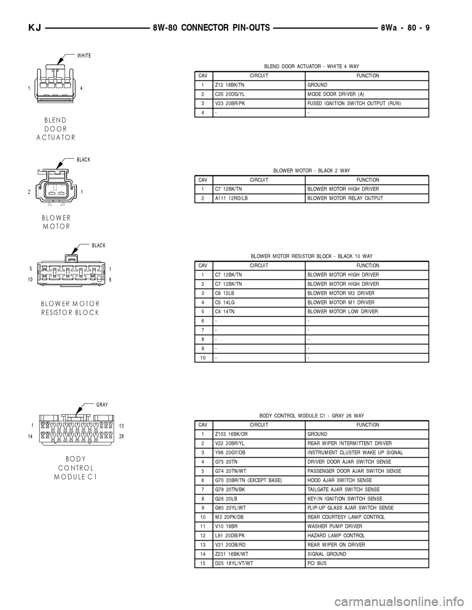
BLEND DOOR ACTUATOR - WHITE 4 WAY
CAV CIRCUIT FUNCTION
1 Z12 18BK/TN GROUND
2 C35 20DG/YL MODE DOOR DRIVER (A)
3 V23 20BR/PK FUSED IGNITION SWITCH OUTPUT (RUN)
4- -
BLOWER MOTOR - BLACK 2 WAY
CAV CIRCUIT FUNCTION
1 C7 12BK/TN BLOWER MOTOR HIGH DRIVER
2 A111 12RD/LB BLOWER MOTOR RELAY OUTPUT
BLOWER MOTOR RESISTOR BLOCK - BLACK 10 WAY
CAV CIRCUIT FUNCTION
1 C7 12BK/TN BLOWER MOTOR HIGH DRIVER
2 C7 12BK/TN BLOWER MOTOR HIGH DRIVER
3 C6 12LB BLOWER MOTOR M2 DRIVER
4 C5 14LG BLOWER MOTOR M1 DRIVER
5 C4 14TN BLOWER MOTOR LOW DRIVER
6- -
7- -
8- -
9- -
10 - -
BODY CONTROL MODULE C1 - GRAY 26 WAY
CAV CIRCUIT FUNCTION
1 Z103 16BK/OR GROUND
2 V22 20BR/YL REAR WIPER INTERMITTENT DRIVER
3 Y98 20GY/DB INSTRUMENT CLUSTER WAKE UP SIGNAL
4 G75 20TN DRIVER DOOR AJAR SWITCH SENSE
5 G74 20TN/WT PASSENGER DOOR AJAR SWITCH SENSE
6 G70 20BR/TN (EXCEPT BASE) HOOD AJAR SWITCH SENSE
7 G78 20TN/BK TAILGATE AJAR SWITCH SENSE
8 G26 20LB KEY-IN IGNITION SWITCH SENSE
9 G80 20YL/WT FLIP-UP GLASS AJAR SWITCH SENSE
10 M3 20PK/DB REAR COURTESY LAMP CONTROL
11 V10 18BR WASHER PUMP DRIVER
12 L91 20DB/PK HAZARD LAMP CONTROL
13 V21 20DB/RD REAR WIPER ON DRIVER
14 Z231 16BK/WT SIGNAL GROUND
15 D25 18YL/VT/WT PCI BUS
KJ8W-80 CONNECTOR PIN-OUTS8Wa-80-9
Page 1120 of 1803
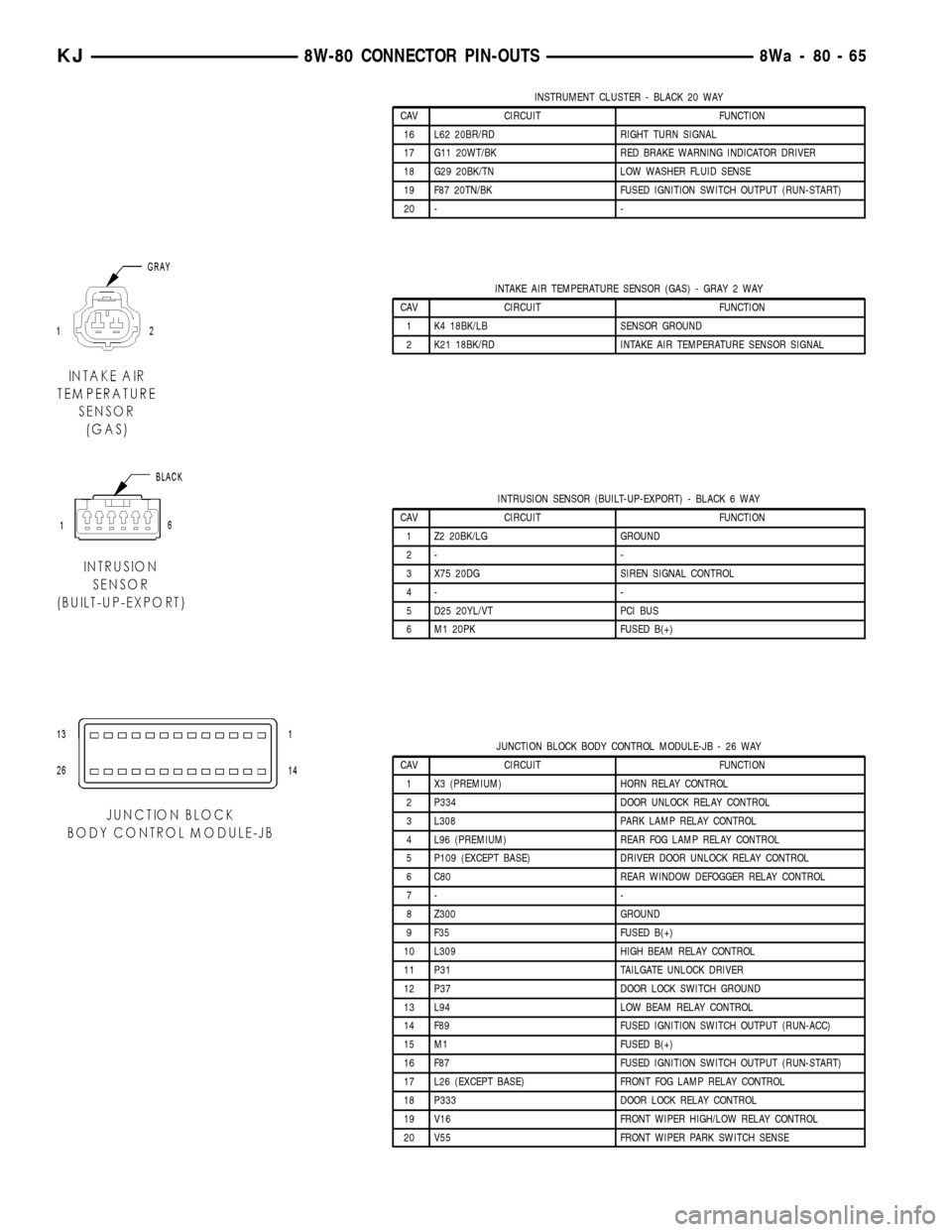
INSTRUMENT CLUSTER - BLACK 20 WAY
CAV CIRCUIT FUNCTION
16 L62 20BR/RD RIGHT TURN SIGNAL
17 G11 20WT/BK RED BRAKE WARNING INDICATOR DRIVER
18 G29 20BK/TN LOW WASHER FLUID SENSE
19 F87 20TN/BK FUSED IGNITION SWITCH OUTPUT (RUN-START)
20 - -
INTAKE AIR TEMPERATURE SENSOR (GAS) - GRAY 2 WAY
CAV CIRCUIT FUNCTION
1 K4 18BK/LB SENSOR GROUND
2 K21 18BK/RD INTAKE AIR TEMPERATURE SENSOR SIGNAL
INTRUSION SENSOR (BUILT-UP-EXPORT) - BLACK 6 WAY
CAV CIRCUIT FUNCTION
1 Z2 20BK/LG GROUND
2- -
3 X75 20DG SIREN SIGNAL CONTROL
4- -
5 D25 20YL/VT PCI BUS
6 M1 20PK FUSED B(+)
JUNCTION BLOCK BODY CONTROL MODULE-JB - 26 WAY
CAV CIRCUIT FUNCTION
1 X3 (PREMIUM) HORN RELAY CONTROL
2 P334 DOOR UNLOCK RELAY CONTROL
3 L308 PARK LAMP RELAY CONTROL
4 L96 (PREMIUM) REAR FOG LAMP RELAY CONTROL
5 P109 (EXCEPT BASE) DRIVER DOOR UNLOCK RELAY CONTROL
6 C80 REAR WINDOW DEFOGGER RELAY CONTROL
7- -
8 Z300 GROUND
9 F35 FUSED B(+)
10 L309 HIGH BEAM RELAY CONTROL
11 P31 TAILGATE UNLOCK DRIVER
12 P37 DOOR LOCK SWITCH GROUND
13 L94 LOW BEAM RELAY CONTROL
14 F89 FUSED IGNITION SWITCH OUTPUT (RUN-ACC)
15 M1 FUSED B(+)
16 F87 FUSED IGNITION SWITCH OUTPUT (RUN-START)
17 L26 (EXCEPT BASE) FRONT FOG LAMP RELAY CONTROL
18 P333 DOOR LOCK RELAY CONTROL
19 V16 FRONT WIPER HIGH/LOW RELAY CONTROL
20 V55 FRONT WIPER PARK SWITCH SENSE
KJ8W-80 CONNECTOR PIN-OUTS8Wa-80-65
Page 1121 of 1803
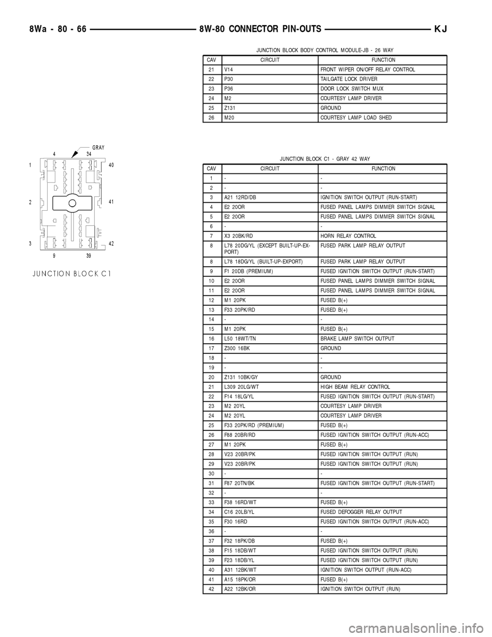
JUNCTION BLOCK BODY CONTROL MODULE-JB - 26 WAY
CAV CIRCUIT FUNCTION
21 V14 FRONT WIPER ON/OFF RELAY CONTROL
22 P30 TAILGATE LOCK DRIVER
23 P36 DOOR LOCK SWITCH MUX
24 M2 COURTESY LAMP DRIVER
25 Z131 GROUND
26 M20 COURTESY LAMP LOAD SHED
JUNCTION BLOCK C1 - GRAY 42 WAY
CAV CIRCUIT FUNCTION
1- -
2- -
3 A21 12RD/DB IGNITION SWITCH OUTPUT (RUN-START)
4 E2 20OR FUSED PANEL LAMPS DIMMER SWITCH SIGNAL
5 E2 20OR FUSED PANEL LAMPS DIMMER SWITCH SIGNAL
6- -
7 X3 20BK/RD HORN RELAY CONTROL
8 L78 20DG/YL (EXCEPT BUILT-UP-EX-
PORT)FUSED PARK LAMP RELAY OUTPUT
8 L78 18DG/YL (BUILT-UP-EXPORT) FUSED PARK LAMP RELAY OUTPUT
9 F1 20DB (PREMIUM) FUSED IGNITION SWITCH OUTPUT (RUN-START)
10 E2 20OR FUSED PANEL LAMPS DIMMER SWITCH SIGNAL
11 E2 20OR FUSED PANEL LAMPS DIMMER SWITCH SIGNAL
12 M1 20PK FUSED B(+)
13 F33 20PK/RD FUSED B(+)
14 - -
15 M1 20PK FUSED B(+)
16 L50 18WT/TN BRAKE LAMP SWITCH OUTPUT
17 Z300 16BK GROUND
18 - -
19 - -
20 Z131 10BK/GY GROUND
21 L309 20LG/WT HIGH BEAM RELAY CONTROL
22 F14 18LG/YL FUSED IGNITION SWITCH OUTPUT (RUN-START)
23 M2 20YL COURTESY LAMP DRIVER
24 M2 20YL COURTESY LAMP DRIVER
25 F33 20PK/RD (PREMIUM) FUSED B(+)
26 F88 20BR/RD FUSED IGNITION SWITCH OUTPUT (RUN-ACC)
27 M1 20PK FUSED B(+)
28 V23 20BR/PK FUSED IGNITION SWITCH OUTPUT (RUN)
29 V23 20BR/PK FUSED IGNITION SWITCH OUTPUT (RUN)
30 - -
31 F87 20TN/BK FUSED IGNITION SWITCH OUTPUT (RUN-START)
32 - -
33 F38 16RD/WT FUSED B(+)
34 C16 20LB/YL FUSED DEFOGGER RELAY OUTPUT
35 F30 16RD FUSED IGNITION SWITCH OUTPUT (RUN-ACC)
36 - -
37 F32 18PK/DB FUSED B(+)
38 F15 18DB/WT FUSED IGNITION SWITCH OUTPUT (RUN)
39 F23 18DB/YL FUSED IGNITION SWITCH OUTPUT (RUN)
40 A31 12BK/WT IGNITION SWITCH OUTPUT (RUN-ACC)
41 A15 18PK/OR FUSED B(+)
42 A22 12BK/OR IGNITION SWITCH OUTPUT (RUN)
8Wa - 80 - 66 8W-80 CONNECTOR PIN-OUTSKJ
Page 1122 of 1803
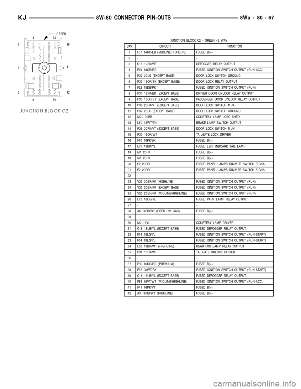
JUNCTION BLOCK C2 - GREEN 42 WAY
CAV CIRCUIT FUNCTION
1 F37 14RD/LB (MIDLINE/HIGHLINE) FUSED B(+)
2- -
3 C15 12BK/WT DEFOGGER RELAY OUTPUT
4 F89 18OR/RD FUSED IGNITION SWITCH OUTPUT (RUN-ACC)
5 P37 20LG (EXCEPT BASE) DOOR LOCK SWITCH GROUND
6 P33 18OR/BK (EXCEPT BASE) DOOR LOCK RELAY OUTPUT
7 F22 18DB/PK FUSED IGNITION SWITCH OUTPUT (RUN)
8 P34 18PK/BK (EXCEPT BASE) DRIVER DOOR UNLOCK RELAY OUTPUT
9 P35 18OR/VT (EXCEPT BASE) PASSENGER DOOR UNLOCK RELAY OUTPUT
10 P36 20PK/VT (EXCEPT BASE) DOOR LOCK SWITCH MUX
11 P37 20LG (EXCEPT BASE) DOOR LOCK SWITCH GROUND
12 M20 20BR COURTESY LAMP LOAD SHED
13 L50 18WT/TN BRAKE LAMP SWITCH OUTPUT
14 P36 20PK/VT (EXCEPT BASE) DOOR LOCK SWITCH MUX
15 P30 16OR/WT TAILGATE LOCK DRIVER
16 F70 18PK/BK FUSED B(+)
17 L77 18BK/YL FUSED LEFT INBOARD TAIL LAMP
18 M1 20PK FUSED B(+)
19 M1 20PK FUSED B(+)
20 E2 20OR FUSED PANEL LAMPS DIMMER SWITCH SIGNAL
21 E2 20OR FUSED PANEL LAMPS DIMMER SWITCH SIGNAL
22 - -
23 V23 20BR/PK (HIGHLINE) FUSED IGNITION SWITCH OUTPUT (RUN)
24 V23 20BR/PK (EXCEPT BASE) FUSED IGNITION SWITCH OUTPUT (RUN)
25 V23 20BR/PK (MIDLINE/HIGHLINE) FUSED IGNITION SWITCH OUTPUT (RUN)
26 L78 18DG/YL FUSED PARK LAMP RELAY OUTPUT
27 - -
28 A6 16RD/BK (PREMIUM GAS) FUSED B(+)
29 - -
30 M2 18YL COURTESY LAMP DRIVER
31 C16 18LB/YL (EXCEPT BASE) FUSED DEFOGGER RELAY OUTPUT
32 F14 18LG/YL FUSED IGNITION SWITCH OUTPUT (RUN-START)
33 F14 18LG/YL FUSED IGNITION SWITCH OUTPUT (RUN-START)
34 L38 18BR/WT (HIGHLINE) REAR FOG LAMP RELAY OUTPUT
35 P31 16PK/WT TAILGATE UNLOCK DRIVER
36 - -
37 F60 16DG/RD (PREMIUM) FUSED B(+)
38 F87 20WT/BK FUSED IGNITION SWITCH OUTPUT (RUN-START)
39 C16 18LB/YL (EXCEPT BASE) FUSED DEFOGGER RELAY OUTPUT
40 F85 16VT/WT (MIDLINE/HIGHLINE) FUSED IGNITION SWITCH OUTPUT (RUN-ACC)
41 F41 16PK/VT FUSED B(+)
42 A3 16RD/WT (HIGHLINE) FUSED B(+)
KJ8W-80 CONNECTOR PIN-OUTS8Wa-80-67
Page 1123 of 1803
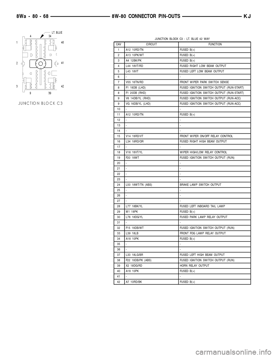
JUNCTION BLOCK C3 - LT. BLUE 42 WAY
CAV CIRCUIT FUNCTION
1 A12 10RD/TN FUSED B(+)
2 A13 10PK/WT FUSED B(+)
3 A4 12BK/PK FUSED B(+)
4 L44 18VT/RD FUSED RIGHT LOW BEAM OUTPUT
5 L43 18VT FUSED LEFT LOW BEAM OUTPUT
6- -
7 V55 16TN/RD FRONT WIPER PARK SWITCH SENSE
8 F1 18DB (LHD) FUSED IGNITION SWITCH OUTPUT (RUN-START)
8 F1 20DB (RHD) FUSED IGNITION SWITCH OUTPUT (RUN-START)
9 V6 14DB/YL (RHD) FUSED IGNITION SWITCH OUTPUT (RUN-ACC)
9 VG 16DB/YL (LHD) FUSED IGNITION SWITCH OUTPUT (RUN-ACC)
10 - -
11 A12 10RD/TN FUSED B(+)
12 - -
13 - -
14 - -
15 V14 18RD/VT FRONT WIPER ON/OFF RELAY CONTROL
16 L34 18RD/OR FUSED RIGHT HIGH BEAM OUTPUT
17 - -
18 V16 18VT/YL WIPER HIGH/LOW RELAY CONTROL
19 F20 18WT FUSED IGNITION SWITCH OUTPUT (RUN)
20 - -
21 - -
22 - -
23 - -
24 L50 18WT/TN (ABS) BRAKE LAMP SWITCH OUTPUT
25 - -
26 - -
27 - -
28 L77 18BK/YL FUSED LEFT INBOARD TAIL LAMP
29 M1 18PK FUSED B(+)
30 L78 18DG/YL FUSED PARK LAMP RELAY OUTPUT
31 - -
32 F15 18DB/WT FUSED IGNITION SWITCH OUTPUT (RUN)
33 L39 18LB FRONT FOG LAMP RELAY OUTPUT
34 A18 10PK FUSED B(+)
35 - -
36 - -
37 L33 18LG/BR FUSED LEFT HIGH BEAM OUTPUT
38 F22 18DB/PK (ABS) FUSED IGNITION SWITCH OUTPUT (RUN)
39 X2 18DG/RD HORN RELAY OUTPUT
40 A18 10PK FUSED B(+)
41 - -
42 A7 10RD/BK FUSED B(+)
8Wa - 80 - 68 8W-80 CONNECTOR PIN-OUTSKJ
Page 1656 of 1803
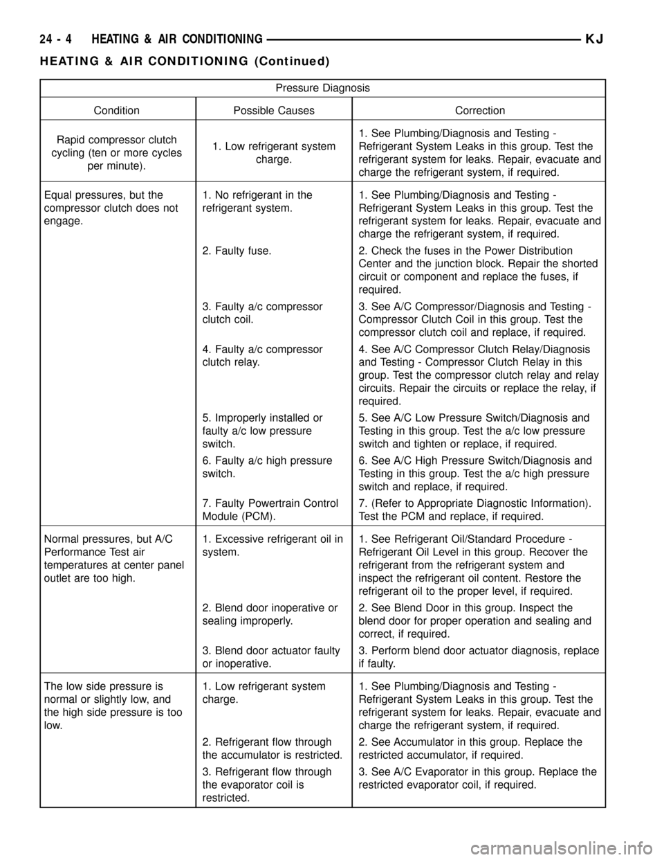
Pressure Diagnosis
Condition Possible Causes Correction
Rapid compressor clutch
cycling (ten or more cycles
per minute).1. Low refrigerant system
charge.1. See Plumbing/Diagnosis and Testing -
Refrigerant System Leaks in this group. Test the
refrigerant system for leaks. Repair, evacuate and
charge the refrigerant system, if required.
Equal pressures, but the
compressor clutch does not
engage.1. No refrigerant in the
refrigerant system.1. See Plumbing/Diagnosis and Testing -
Refrigerant System Leaks in this group. Test the
refrigerant system for leaks. Repair, evacuate and
charge the refrigerant system, if required.
2. Faulty fuse. 2. Check the fuses in the Power Distribution
Center and the junction block. Repair the shorted
circuit or component and replace the fuses, if
required.
3. Faulty a/c compressor
clutch coil.3. See A/C Compressor/Diagnosis and Testing -
Compressor Clutch Coil in this group. Test the
compressor clutch coil and replace, if required.
4. Faulty a/c compressor
clutch relay.4. See A/C Compressor Clutch Relay/Diagnosis
and Testing - Compressor Clutch Relay in this
group. Test the compressor clutch relay and relay
circuits. Repair the circuits or replace the relay, if
required.
5. Improperly installed or
faulty a/c low pressure
switch.5. See A/C Low Pressure Switch/Diagnosis and
Testing in this group. Test the a/c low pressure
switch and tighten or replace, if required.
6. Faulty a/c high pressure
switch.6. See A/C High Pressure Switch/Diagnosis and
Testing in this group. Test the a/c high pressure
switch and replace, if required.
7. Faulty Powertrain Control
Module (PCM).7. (Refer to Appropriate Diagnostic Information).
Test the PCM and replace, if required.
Normal pressures, but A/C
Performance Test air
temperatures at center panel
outlet are too high.1. Excessive refrigerant oil in
system.1. See Refrigerant Oil/Standard Procedure -
Refrigerant Oil Level in this group. Recover the
refrigerant from the refrigerant system and
inspect the refrigerant oil content. Restore the
refrigerant oil to the proper level, if required.
2. Blend door inoperative or
sealing improperly.2. See Blend Door in this group. Inspect the
blend door for proper operation and sealing and
correct, if required.
3. Blend door actuator faulty
or inoperative.3. Perform blend door actuator diagnosis, replace
if faulty.
The low side pressure is
normal or slightly low, and
the high side pressure is too
low.1. Low refrigerant system
charge.1. See Plumbing/Diagnosis and Testing -
Refrigerant System Leaks in this group. Test the
refrigerant system for leaks. Repair, evacuate and
charge the refrigerant system, if required.
2. Refrigerant flow through
the accumulator is restricted.2. See Accumulator in this group. Replace the
restricted accumulator, if required.
3. Refrigerant flow through
the evaporator coil is
restricted.3. See A/C Evaporator in this group. Replace the
restricted evaporator coil, if required.
24 - 4 HEATING & AIR CONDITIONINGKJ
HEATING & AIR CONDITIONING (Continued)
Page 1664 of 1803

A/C COMPRESSOR CLUTCH
DESCRIPTION - 3.7L and 2.4L
The compressor clutch assembly consists of a sta-
tionary electromagnetic coil, a rotor bearing and
rotor assembly, and a clutch plate (Fig. 1). The elec-
tromagnetic coil unit and the rotor bearing and rotor
assembly are each retained on the nose of the com-
pressor front housing with snap rings. The clutch
plate is keyed to the compressor shaft and secured
with a nut. These components provide the means to
engage and disengage the compressor from the
engine serpentine accessory drive belt.
OPERATION - 3.7L and 2.4L
When the clutch coil is energized, it magnetically
draws the clutch into contact with the rotor and
drives the compressor shaft. When the coil is not
energized, the rotor freewheels on the clutch rotor
bearing, which is part of the rotor. The compressor
clutch and coil are the only serviced parts on the
compressor.
The compressor clutch engagement is controlled by
several components: the A/C Heater mode control
switch, the A/C low pressure switch, the A/C high
pressure switch, the compressor clutch relay, and the
Powertrain Control Module (PCM). The PCM may
delay compressor clutch engagement for up to thirty
seconds. Refer to Electronic Control Modules for
more information on the PCM controls.
DIAGNOSIS AND TESTING - A/C COMPRESSOR
CLUTCH COIL
For circuit descriptions and diagrams, (Refer to
Appropriate Wiring Information). The battery must
be fully-charged before performing the following
tests. Refer to Battery for more information.
(1) Connect an ammeter (0 to 10 ampere scale) in
series with the clutch coil terminal. Use a voltmeter
(0 to 20 volt scale) with clip-type leads for measuring
the voltage across the battery and the compressor
clutch coil.
(2) With the A/C Heater mode control switch in
any A/C mode, and the blower motor switch in the
lowest speed position, start the engine and run it at
normal idle.
(3) The compressor clutch coil voltage should read
within 0.2 volts of the battery voltage. If there is
voltage at the clutch coil, but the reading is not
within 0.2 volts of the battery voltage, test the clutch
coil feed circuit for excessive voltage drop and repair
as required. If there is no voltage reading at the
clutch coil, use a DRB IIItscan tool and (Refer to
Appropriate Diagnostic Information) for testing of the
compressor clutch circuit and PCM control. The fol-
lowing components must be checked and repaired as
required before you can complete testing of the clutch
coil:
²Fuses in the junction block and the Power Dis-
tribution Center (PDC)
²A/C heater mode control switch
²Compressor clutch relay
²A/C high pressure switch
²A/C low pressure switch
²Powertrain Control Module (PCM).
(4) The compressor clutch coil is acceptable if the
current draw measured at the clutch coil is 2.0 to 3.9
amperes with the electrical system voltage at 11.5 to
12.5 volts. This should only be checked with the work
area temperature at 21É C (70É F). If system voltage
is more than 12.5 volts, add electrical loads by turn-
ing on electrical accessories until the system voltage
drops below 12.5 volts.
(a) If the clutch coil current reading is four
amperes or more, the coil is shorted and should be
replaced.
(b) If the clutch coil current reading is zero, the
coil is open and should be replaced.
STANDARD PROCEDURE - A/C COMPRESSOR
CLUTCH BREAK-IN
After a new compressor clutch has been installed,
cycle the compressor clutch approximately twenty
times (five seconds on, then five seconds off). During
this procedure, set the A/C Heater control to the
Recirculation Mode, the blower motor switch in the
highest speed position, and the engine speed at 1500
Fig. 1 COMPRESSOR CLUTCH - TYPICAL
1 - CLUTCH PLATE
2 - NOT USED ON KJ
3 - ROTOR
4 - COIL
5 - CLUTCH SHIMS
6 - SNAP RING
7 - SNAP RING
24 - 12 CONTROLSKJ