2002 JEEP LIBERTY alignment
[x] Cancel search: alignmentPage 1409 of 1803
(14) Continue lowering tank while guiding remain-
ing hoses and lines.
(15) If fuel tank is to be replaced, remove LDP,
fuel filter and fuel pump module from tank. Refer to
Leak Detection Pump, Fuel Filter and Fuel Pump
Module Removal/Installation procedures.
INSTALLATION
(1) If fuel tank is to be replaced, install LDP, fuel
filter and fuel pump module to tank. Refer to Leak
Detection Pump, Fuel Filter and Fuel Pump Module
Removal/Installation procedures.
(2) Position fuel tank to hydraulic jack.
(3) Raise tank while carefully guiding vent tubes/
hoses through frame rail and crossmember. Before
tank reaches body, connect electrical connector to
Leak Detection Pump (LDP).
(4) Continue raising tank until positioned to body.
(5) Attach two fuel tank mounting straps and 4
mounting bolts. Tighten bolts to 61 N´m (45 ft. lbs.)
torque.
(6) Connect 2 hoses to body retention clip at left/
front of tank.
(7) Connect fuel filter fuel line to main fuel line
(snaps together). After connecting, snap this line into
body retention clip. Also connect LDP vacuum hose
near this point.(8) Install fuel fill hose and hose clamp to fuel
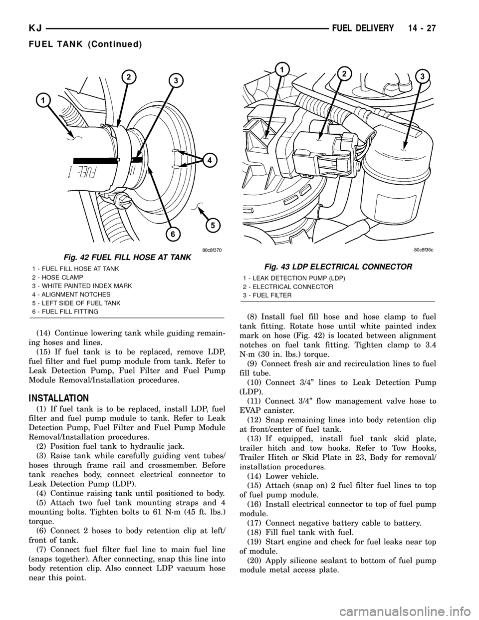
tank fitting. Rotate hose until white painted index
mark on hose (Fig. 42) is located between alignment
notches on fuel tank fitting. Tighten clamp to 3.4
N´m (30 in. lbs.) torque.
(9) Connect fresh air and recirculation lines to fuel
fill tube.
(10) Connect 3/4º lines to Leak Detection Pump
(LDP).
(11) Connect 3/4º flow management valve hose to
EVAP canister.
(12) Snap remaining lines into body retention clip
at front/center of fuel tank.
(13) If equipped, install fuel tank skid plate,
trailer hitch and tow hooks. Refer to Tow Hooks,
Trailer Hitch or Skid Plate in 23, Body for removal/
installation procedures.
(14) Lower vehicle.
(15) Attach (snap on) 2 fuel filter fuel lines to top
of fuel pump module.
(16) Install electrical connector to top of fuel pump
module.
(17) Connect negative battery cable to battery.
(18) Fill fuel tank with fuel.
(19) Start engine and check for fuel leaks near top
of module.
(20) Apply silicone sealant to bottom of fuel pump
module metal access plate.
Fig. 42 FUEL FILL HOSE AT TANK
1 - FUEL FILL HOSE AT TANK
2 - HOSE CLAMP
3 - WHITE PAINTED INDEX MARK
4 - ALIGNMENT NOTCHES
5 - LEFT SIDE OF FUEL TANK
6 - FUEL FILL FITTINGFig. 43 LDP ELECTRICAL CONNECTOR
1 - LEAK DETECTION PUMP (LDP)
2 - ELECTRICAL CONNECTOR
3 - FUEL FILTER
KJFUEL DELIVERY 14 - 27
FUEL TANK (Continued)
Page 1421 of 1803

The range of voltage output from the sensor is usually
between 4.6 volts at sea level to as low as 0.3 volts at
26 in. of Hg. Barometric pressure is the pressure
exerted by the atmosphere upon an object. At sea level
on a standard day, no storm, barometric pressure is
approximately 29.92 in Hg. For every 100 feet of alti-
tude, barometric pressure drops 0.10 in. Hg. If a storm
goes through, it can change barometric pressure from
what should be present for that altitude. You should
know what the average pressure and corresponding
barometric pressure is for your area.
REMOVAL
2.4L
The Manifold Absolute Pressure (MAP) sensor is
mounted into the rear of the intake manifold (Fig.
17). An o-ring is used to seal the sensor to the intake
manifold (Fig. 19).
(1) Disconnect electrical connector at sensor.
(2) Clean area around MAP sensor.
(3) Remove sensor mounting screw (TORX head).
(4) Remove MAP sensor from intake manifold.
(5) Check condition of sensor o-ring (Fig. 19).
3.7L
The Manifold Absolute Pressure (MAP) sensor is
mounted into the front of the intake manifold (Fig.
18). An o-ring is used to seal the sensor to the intake
manifold (Fig. 19).(1) Disconnect electrical connector at sensor.
(2) Clean area around MAP sensor.
(3) Remove 2 sensor mounting screws.
(4) Remove MAP sensor from intake manifold.
(5) Check condition of sensor o-ring (Fig. 19).
Fig. 17 MAP SENSOR LOCATION-2.4L
1 - REAR OF INTAKE MANIFOLD
2 - MAP SENSOR
3 - ALIGNMENT PIN
4 - MOUNTING BOLT (TORX)
5 - ELECTRICAL CONNECTOR
6 - MAIN ENGINE HARNESS CONNECTORS
Fig. 18 MAP SENSOR / ECT SENSOR - 3.7L
1 - MOUNTING SCREWS
2 - MAP SENSOR
3 - ECT SENSOR
Fig. 19 MAP SENSOR O-RING
1 - MAP SENSOR
2 - O-RING
KJFUEL INJECTION 14 - 39
MAP SENSOR (Continued)
Page 1432 of 1803
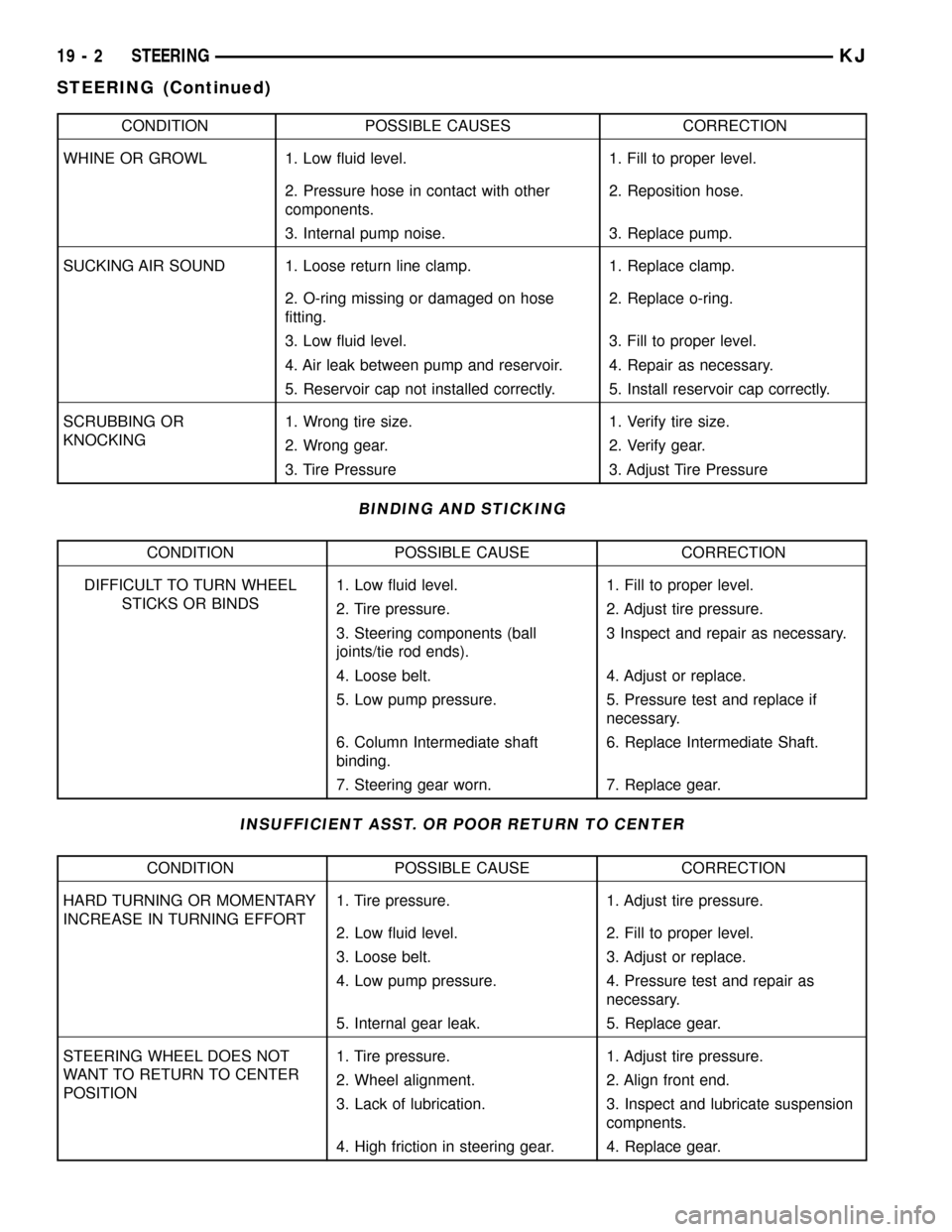
CONDITION POSSIBLE CAUSES CORRECTION
WHINE OR GROWL 1. Low fluid level. 1. Fill to proper level.
2. Pressure hose in contact with other
components.2. Reposition hose.
3. Internal pump noise. 3. Replace pump.
SUCKING AIR SOUND 1. Loose return line clamp. 1. Replace clamp.
2. O-ring missing or damaged on hose
fitting.2. Replace o-ring.
3. Low fluid level. 3. Fill to proper level.
4. Air leak between pump and reservoir. 4. Repair as necessary.
5. Reservoir cap not installed correctly. 5. Install reservoir cap correctly.
SCRUBBING OR
KNOCKING1. Wrong tire size. 1. Verify tire size.
2. Wrong gear. 2. Verify gear.
3. Tire Pressure 3. Adjust Tire Pressure
BINDING AND STICKING
CONDITION POSSIBLE CAUSE CORRECTION
DIFFICULT TO TURN WHEEL
STICKS OR BINDS1. Low fluid level. 1. Fill to proper level.
2. Tire pressure. 2. Adjust tire pressure.
3. Steering components (ball
joints/tie rod ends).3 Inspect and repair as necessary.
4. Loose belt. 4. Adjust or replace.
5. Low pump pressure. 5. Pressure test and replace if
necessary.
6. Column Intermediate shaft
binding.6. Replace Intermediate Shaft.
7. Steering gear worn. 7. Replace gear.
INSUFFICIENT ASST. OR POOR RETURN TO CENTER
CONDITION POSSIBLE CAUSE CORRECTION
HARD TURNING OR MOMENTARY
INCREASE IN TURNING EFFORT1. Tire pressure. 1. Adjust tire pressure.
2. Low fluid level. 2. Fill to proper level.
3. Loose belt. 3. Adjust or replace.
4. Low pump pressure. 4. Pressure test and repair as
necessary.
5. Internal gear leak. 5. Replace gear.
STEERING WHEEL DOES NOT
WANT TO RETURN TO CENTER
POSITION1. Tire pressure. 1. Adjust tire pressure.
2. Wheel alignment. 2. Align front end.
3. Lack of lubrication. 3. Inspect and lubricate suspension
compnents.
4. High friction in steering gear. 4. Replace gear.
19 - 2 STEERINGKJ
STEERING (Continued)
Page 1433 of 1803
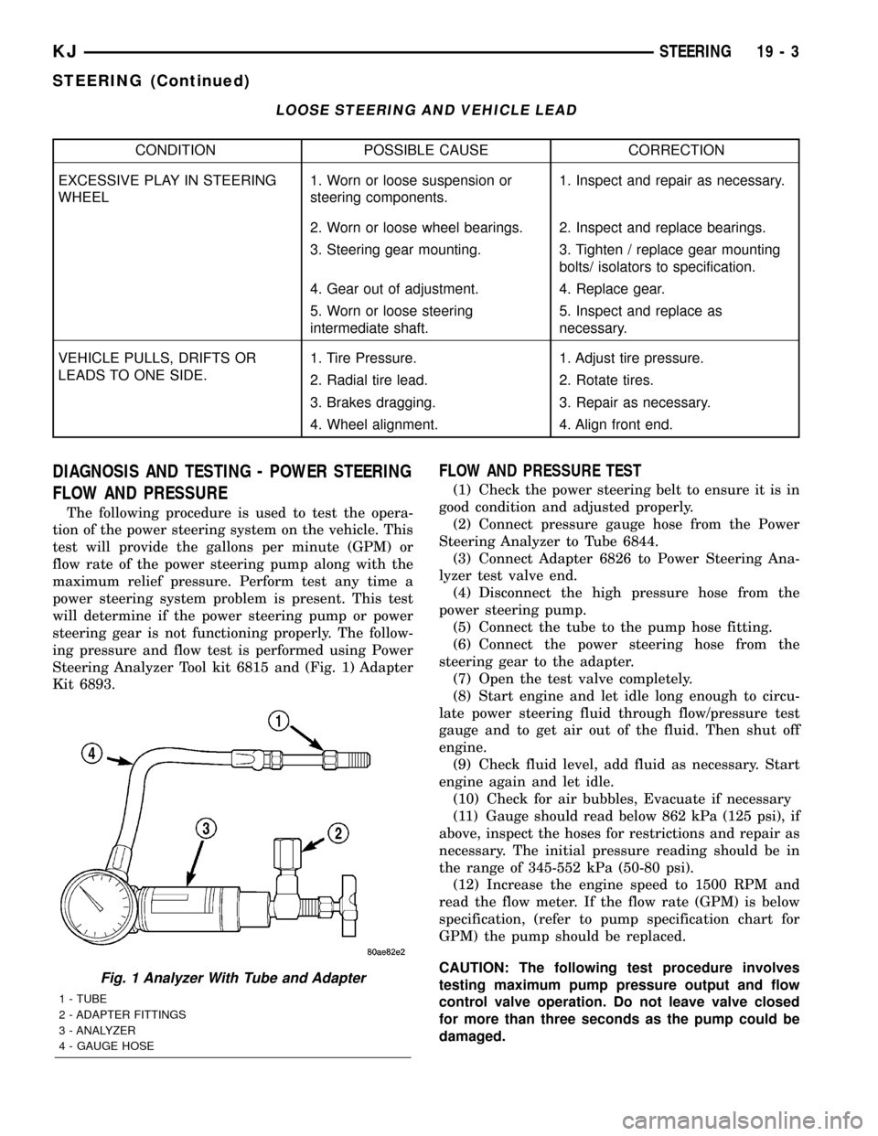
LOOSE STEERING AND VEHICLE LEAD
CONDITION POSSIBLE CAUSE CORRECTION
EXCESSIVE PLAY IN STEERING
WHEEL1. Worn or loose suspension or
steering components.1. Inspect and repair as necessary.
2. Worn or loose wheel bearings. 2. Inspect and replace bearings.
3. Steering gear mounting. 3. Tighten / replace gear mounting
bolts/ isolators to specification.
4. Gear out of adjustment. 4. Replace gear.
5. Worn or loose steering
intermediate shaft.5. Inspect and replace as
necessary.
VEHICLE PULLS, DRIFTS OR
LEADS TO ONE SIDE.1. Tire Pressure. 1. Adjust tire pressure.
2. Radial tire lead. 2. Rotate tires.
3. Brakes dragging. 3. Repair as necessary.
4. Wheel alignment. 4. Align front end.
DIAGNOSIS AND TESTING - POWER STEERING
FLOW AND PRESSURE
The following procedure is used to test the opera-
tion of the power steering system on the vehicle. This
test will provide the gallons per minute (GPM) or
flow rate of the power steering pump along with the
maximum relief pressure. Perform test any time a
power steering system problem is present. This test
will determine if the power steering pump or power
steering gear is not functioning properly. The follow-
ing pressure and flow test is performed using Power
Steering Analyzer Tool kit 6815 and (Fig. 1) Adapter
Kit 6893.
FLOW AND PRESSURE TEST
(1) Check the power steering belt to ensure it is in
good condition and adjusted properly.
(2) Connect pressure gauge hose from the Power
Steering Analyzer to Tube 6844.
(3) Connect Adapter 6826 to Power Steering Ana-
lyzer test valve end.
(4) Disconnect the high pressure hose from the
power steering pump.
(5) Connect the tube to the pump hose fitting.
(6) Connect the power steering hose from the
steering gear to the adapter.
(7) Open the test valve completely.
(8) Start engine and let idle long enough to circu-
late power steering fluid through flow/pressure test
gauge and to get air out of the fluid. Then shut off
engine.
(9) Check fluid level, add fluid as necessary. Start
engine again and let idle.
(10) Check for air bubbles, Evacuate if necessary
(11) Gauge should read below 862 kPa (125 psi), if
above, inspect the hoses for restrictions and repair as
necessary. The initial pressure reading should be in
the range of 345-552 kPa (50-80 psi).
(12) Increase the engine speed to 1500 RPM and
read the flow meter. If the flow rate (GPM) is below
specification, (refer to pump specification chart for
GPM) the pump should be replaced.
CAUTION: The following test procedure involves
testing maximum pump pressure output and flow
control valve operation. Do not leave valve closed
for more than three seconds as the pump could be
damaged.
Fig. 1 Analyzer With Tube and Adapter
1 - TUBE
2 - ADAPTER FITTINGS
3 - ANALYZER
4 - GAUGE HOSE
KJSTEERING 19 - 3
STEERING (Continued)
Page 1443 of 1803

GEAR
TABLE OF CONTENTS
page page
GEAR
DESCRIPTION.........................13
OPERATION...........................13
REMOVAL
REMOVAL - 4WD......................13
REMOVAL - 2WD......................14
INSTALLATION
INSTALLATION - 4WD..................14INSTALLATION - 2WD..................14
SPECIFICATIONS
TORQUE CHART......................15
SPECIAL TOOLS
OUTER TIE ROD END REMOVAL TOOL....15
GEAR
DESCRIPTION
A rack and pinion steering gear (Fig. 1) is made up
of two main components, the pinon shaft and the
rack. The gear cannot be adjusted or internally ser-
viced. If a malfunction or a fluid leak occurs, the gear
must be replaced as an assembly.
OPERATION
The steering column intermediate shaft is attached
to the gear pinion. The rotation of the pinion moves
the gear rack from side-to-side. This lateral action of
the rack pushes and pulls the tie rods, which are
connected to the steering knuckles to change the
direction of the front wheels.
REMOVAL
REMOVAL - 4WD
(1) Siphon the power steering fluid from the power
steering reservoir.
(2) Lock the steering wheel to prevent spinning of
the clockspring.
(3) Raise and support the vehicle.
(4) Remove the skid plate from under the front
end to gain access to the gear (Refer to 13 - FRAME
& BUMPERS/FRAME/FRONT SKID PLATE -
REMOVAL).
(5) Remove the front tire and wheel assemblies.
NOTE: Mark the alignment adjusting cams for eas-
ier installation.
(6) Remove the lower control arms. (Refer to 2 -
SUSPENSION/FRONT/LOWER CONTROL ARM -
REMOVAL).
(7) Remove the front axle. (Refer to 3 - DIFFER-
ENTIAL & DRIVELINE/FRONT AXLE - REMOV-
AL).
(8) Remove the tie rod end nuts.
(9) Separate tie rod ends from the knuckles with
Puller C-3894-A.
(10) Remove the intermediate shaft lower coupler
bolt and slide the coupler off the gear (Fig. 2).
(11) Remove power steering pressure hose bracket
(Fig. 3).
(12) Remove the power steering lines from the
gear (Fig. 2).
(13) Remove the mounting bolts from the gear to
the front cradle (Fig. 3).
(14) Remove the steering gear from the vehicle.
Fig. 1 Rack & Pinion Steering Gear
1 - TIE ROD - INNER
2 - TIE ROD - INNER
3 - TIE ROD END - OUTER LH
4 - BOOTS
5 - TIE ROD END - OUTER RH
KJGEAR 19 - 13
Page 1444 of 1803

REMOVAL - 2WD
(1) Siphon the power steering fluid from the power
steering reservoir.
(2) Lock the steering wheel to prevent spinning of
the clockspring.
(3) Raise and support the vehicle.
(4) Remove the skid plate from under the front
end to gain access to the gear(Refer to 13 - FRAME
& BUMPERS/FRAME/FRONT SKID PLATE -
REMOVAL).
(5) Remove the tire and wheel assembly.
NOTE: Mark the alignment adjusting cams and tie
rod end jam nuts on the steering gear for easier
installation.
(6) Remove the tie rod end nuts.
(7) Separate tie rod ends from the knuckles with
Puller C-3894-A.
(8) Remove the lower intermediate shaft coupler
bolt and slide the coupler off the gear (Fig. 2).(9) Remove power steering pressure hose bracket
(Fig. 3).
(10) Remove the power steering lines from the
gear (Fig. 2).
(11) Remove the mounting bolts from the gear to
the front cradle (Fig. 3).
(12) Remove the steering gear from the vehicle.
INSTALLATION
INSTALLATION - 4WD
(1) Transfer the tie rod ends to the new steering
gear (if needed).
(2) Install the steering gear to the vehicle.
(3) Install the gear mounting bolts to the front cra-
dle. (Fig. 3). Tighten the gear mounting bolts to 162
N´m (120 ft.lbs.)
(4) Install the power steering lines to the gear
(Fig. 2).
(5) Install the power steering pressure hose
bracket (Fig. 3).
(6) Install the lower coupler bolt and slide the cou-
pler on to the gear (Fig. 2).
(7) Install the tie rod end to the knuckle and
tighten the nuts.
(8) Install the front axle. (Refer to 3 - DIFFEREN-
TIAL & DRIVELINE/FRONT AXLE - INSTALLA-
TION).
(9) Install the lower control arms. (Refer to 2 -
SUSPENSION/FRONT/LOWER CONTROL ARM -
INSTALLATION).
(10) Install the tire and wheel assembly. (Refer to
22 - TIRES/WHEELS/WHEELS - STANDARD PRO-
CEDURE).
(11) Install the skid plate (Refer to 13 - FRAME &
BUMPERS/FRAME/FRONT SKID PLATE - INSTAL-
LATION).
(12) Lower the vehicle.
(13) Unlock the steering wheel.
(14) Fill the power steering fluid (Refer to 19 -
STEERING/PUMP - STANDARD PROCEDURE).
(15) Reset the toe and center the steering wheel
(Refer to 2 - SUSPENSION/WHEEL ALIGNMENT -
STANDARD PROCEDURE).
INSTALLATION - 2WD
(1) Transfer the outer tie rod ends to the new
steering gear (if needed).
(2) Install the steering gear to the vehicle.
(3) Install the gear mounting bolts to the front cra-
dle. (Fig. 3). Tighten the gear mounting bolts to 162
N´m (120 ft.lbs.)
(4) Install the power steering lines to the gear
(Fig. 2).
Fig. 2 COUPLER BOLT
Fig. 3 RACK & PINION
19 - 14 GEARKJ
GEAR (Continued)
Page 1445 of 1803
(5) Install the power steering pressure hose
bracket (Fig. 3).
(6) Install the lower coupler bolt and slide the cou-
pler on to the gear (Fig. 2).
(7) Install the tie rod end to the knuckle and
tighten the nuts.
(8) Install the tire and wheel assembly. (Refer to
22 - TIRES/WHEELS/WHEELS - STANDARD PRO-
CEDURE).
(9) Install the skid plate(Refer to 13 - FRAME &
BUMPERS/FRAME/FRONT SKID PLATE - INSTAL-
LATION).(10) Lower the vehicle.
(11) Unlock the steering wheel.
(12) Fill the power steering fluid (Refer to 19 -
STEERING/PUMP - STANDARD PROCEDURE).
(13) Reset the toe and center the steering wheel
(Refer to 2 - SUSPENSION/WHEEL ALIGNMENT -
STANDARD PROCEDURE).
SPECIFICATIONS
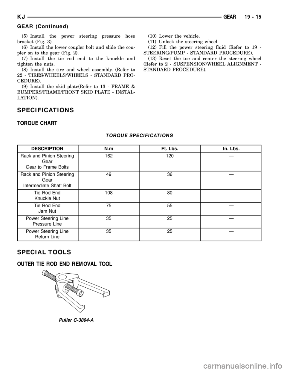
TORQUE CHART
TORQUE SPECIFICATIONS
DESCRIPTION N´m Ft. Lbs. In. Lbs.
Rack and Pinion Steering
Gear
Gear to Frame Bolts162 120 Ð
Rack and Pinion Steering
Gear
Intermediate Shaft Bolt49 36 Ð
Tie Rod End
Knuckle Nut108 80 Ð
Tie Rod End
Jam Nut75 55 Ð
Power Steering Line
Pressure Line35 25 Ð
Power Steering Line
Return Line35 25 Ð
SPECIAL TOOLS
OUTER TIE ROD END REMOVAL TOOL
Puller C-3894-A
KJGEAR 19 - 15
GEAR (Continued)
Page 1446 of 1803

LINKAGE
TABLE OF CONTENTS
page page
LINKAGE
STANDARD PROCEDURE - STEERING
LINKAGE............................16TIE ROD END
REMOVAL.............................16
INSTALLATION.........................16
LINKAGE
STANDARD PROCEDURE - STEERING LINKAGE
The tie rod end and ball stud seals should be
inspected during all oil changes. If a seal is damaged,
replace the tie rod.
CAUTION: If any steering components are replaced
or serviced an alignment must be performed, to
ensure the vehicle meets all alignment specifica-
tions.
TIE ROD END
REMOVAL
(1) Raise and support the vehicle.
(2) Remove the tire and wheel assembly.
NOTE: Mark the tie rod end jam nuts on the steer-
ing gear for easier installation.
(3) Loosen the tie rod end jam nut (Fig. 1).
(4) Remove the tie rod end nut (Fig. 1).
(5) Seperate the tie rod end from the knuckle
using tool C3894A.
NOTE: Count the number of turns when removing.
(6) Remove the tie rod end from the rack (Fig. 1).
INSTALLATION
(1) Install the tie rod end to the rack to the exact
number of turns that it was removed (Fig. 1).(2) Install the tie rod end to the knuckle. Tighten
the nut to 108 N´m (80 ft.lbs).
(3) Tighten the jam nut to 76 N´m (55 ft.lbs). (Fig.
1).
(4) Install the tire and wheel assembly. (Refer to
22 - TIRES/WHEELS/WHEELS - STANDARD PRO-
CEDURE).
(5) Reset the toe and center the steering wheel
(Refer to 2 - SUSPENSION/WHEEL ALIGNMENT -
STANDARD PROCEDURE).
Fig. 1 TIE ROD END
1 - JAM NUT
2 - TIE ROD - INNER
3 - TIE ROD END - OUTER
19 - 16 LINKAGEKJ