2002 JEEP LIBERTY Cooling
[x] Cancel search: CoolingPage 1340 of 1803
VIBRATION DAMPER
REMOVAL
(1) Remove accesory drive belts. (Refer to 7 -
COOLING/ACCESSORY DRIVE/DRIVE BELTS -
REMOVAL)
(2) Remove crankshaft damper bolt.
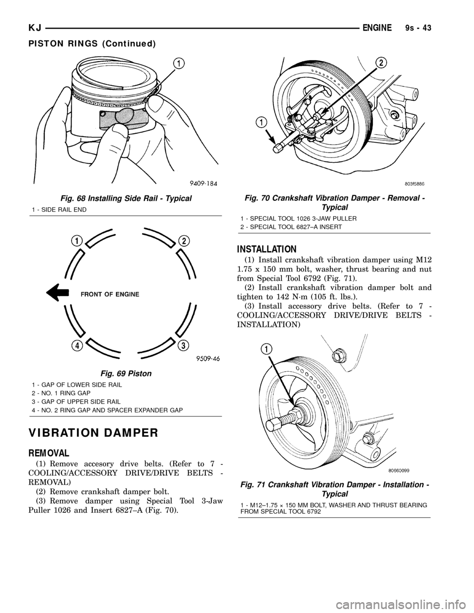
(3) Remove damper using Special Tool 3-Jaw
Puller 1026 and Insert 6827±A (Fig. 70).
INSTALLATION
(1) Install crankshaft vibration damper using M12
1.75 x 150 mm bolt, washer, thrust bearing and nut
from Special Tool 6792 (Fig. 71).
(2) Install crankshaft vibration damper bolt and
tighten to 142 N´m (105 ft. lbs.).
(3) Install accessory drive belts. (Refer to 7 -
COOLING/ACCESSORY DRIVE/DRIVE BELTS -
INSTALLATION)
Fig. 68 Installing Side Rail - Typical
1 - SIDE RAIL END
Fig. 69 Piston
1 - GAP OF LOWER SIDE RAIL
2 - NO. 1 RING GAP
3 - GAP OF UPPER SIDE RAIL
4 - NO. 2 RING GAP AND SPACER EXPANDER GAP
Fig. 70 Crankshaft Vibration Damper - Removal -
Typical
1 - SPECIAL TOOL 1026 3-JAW PULLER
2 - SPECIAL TOOL 6827±A INSERT
Fig. 71 Crankshaft Vibration Damper - Installation -
Typical
1 - M12±1.75 ý 150 MM BOLT, WASHER AND THRUST BEARING
FROM SPECIAL TOOL 6792
KJENGINE9s-43
PISTON RINGS (Continued)
Page 1350 of 1803
EXHAUST MANIFOLD
DESCRIPTION
The exhaust manifold is made of Hi-Silicone Moly
nodular cast iron for strength and high tempera-
tures. The manifold attaches to the cylinder head.
OPERATION
The exhaust manifold collects the exhaust gasses
exiting the combustion chambers. Then it channels
the exhaust gasses to the exhaust pipe attached to
the manifold.
REMOVAL
(1) Raise vehicle and disconnect exhaust pipe from
the exhaust manifold.
(2) Lower the vehicle.
(3) Disconnect upstream oxygen sensor connector
at the rear of exhaust manifold.
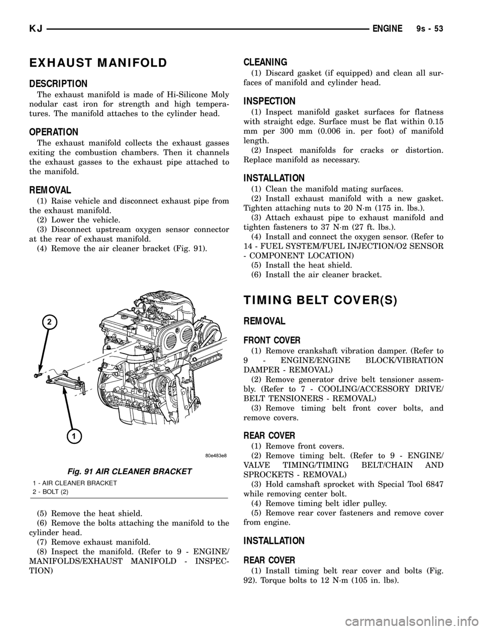
(4) Remove the air cleaner bracket (Fig. 91).
(5) Remove the heat shield.
(6) Remove the bolts attaching the manifold to the
cylinder head.
(7) Remove exhaust manifold.
(8) Inspect the manifold. (Refer to 9 - ENGINE/
MANIFOLDS/EXHAUST MANIFOLD - INSPEC-
TION)
CLEANING
(1) Discard gasket (if equipped) and clean all sur-
faces of manifold and cylinder head.
INSPECTION
(1) Inspect manifold gasket surfaces for flatness
with straight edge. Surface must be flat within 0.15
mm per 300 mm (0.006 in. per foot) of manifold
length.
(2) Inspect manifolds for cracks or distortion.
Replace manifold as necessary.
INSTALLATION
(1) Clean the manifold mating surfaces.
(2) Install exhaust manifold with a new gasket.
Tighten attaching nuts to 20 N´m (175 in. lbs.).
(3) Attach exhaust pipe to exhaust manifold and
tighten fasteners to 37 N´m (27 ft. lbs.).
(4) Install and connect the oxygen sensor. (Refer to
14 - FUEL SYSTEM/FUEL INJECTION/O2 SENSOR
- COMPONENT LOCATION)
(5) Install the heat shield.
(6) Install the air cleaner bracket.
TIMING BELT COVER(S)
REMOVAL
FRONT COVER
(1) Remove crankshaft vibration damper. (Refer to
9 - ENGINE/ENGINE BLOCK/VIBRATION
DAMPER - REMOVAL)
(2) Remove generator drive belt tensioner assem-
bly. (Refer to 7 - COOLING/ACCESSORY DRIVE/
BELT TENSIONERS - REMOVAL)
(3) Remove timing belt front cover bolts, and
remove covers.
REAR COVER
(1) Remove front covers.
(2) Remove timing belt. (Refer to 9 - ENGINE/
VALVE TIMING/TIMING BELT/CHAIN AND
SPROCKETS - REMOVAL)
(3) Hold camshaft sprocket with Special Tool 6847
while removing center bolt.
(4) Remove timing belt idler pulley.
(5) Remove rear cover fasteners and remove cover
from engine.
INSTALLATION
REAR COVER
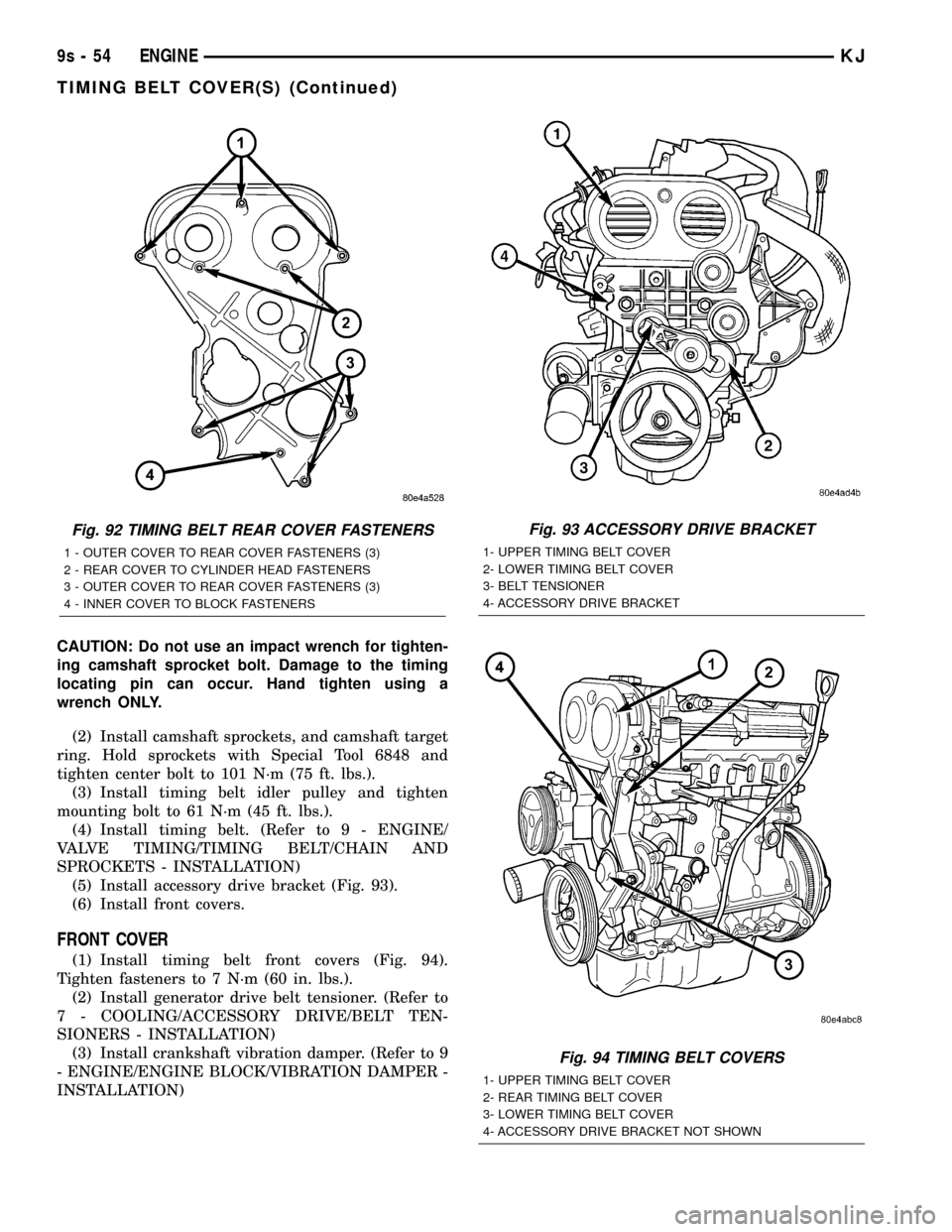
(1) Install timing belt rear cover and bolts (Fig.
92). Torque bolts to 12 N´m (105 in. lbs).
Fig. 91 AIR CLEANER BRACKET
1 - AIR CLEANER BRACKET
2 - BOLT (2)
KJENGINE9s-53
Page 1351 of 1803
CAUTION: Do not use an impact wrench for tighten-
ing camshaft sprocket bolt. Damage to the timing
locating pin can occur. Hand tighten using a
wrench ONLY.
(2) Install camshaft sprockets, and camshaft target
ring. Hold sprockets with Special Tool 6848 and
tighten center bolt to 101 N´m (75 ft. lbs.).
(3) Install timing belt idler pulley and tighten
mounting bolt to 61 N´m (45 ft. lbs.).
(4) Install timing belt. (Refer to 9 - ENGINE/
VALVE TIMING/TIMING BELT/CHAIN AND
SPROCKETS - INSTALLATION)
(5) Install accessory drive bracket (Fig. 93).
(6) Install front covers.
FRONT COVER
(1) Install timing belt front covers (Fig. 94).
Tighten fasteners to 7 N´m (60 in. lbs.).
(2) Install generator drive belt tensioner. (Refer to
7 - COOLING/ACCESSORY DRIVE/BELT TEN-
SIONERS - INSTALLATION)
(3) Install crankshaft vibration damper. (Refer to 9
- ENGINE/ENGINE BLOCK/VIBRATION DAMPER -
INSTALLATION)
Fig. 92 TIMING BELT REAR COVER FASTENERS
1 - OUTER COVER TO REAR COVER FASTENERS (3)
2 - REAR COVER TO CYLINDER HEAD FASTENERS
3 - OUTER COVER TO REAR COVER FASTENERS (3)
4 - INNER COVER TO BLOCK FASTENERS
Fig. 93 ACCESSORY DRIVE BRACKET
1- UPPER TIMING BELT COVER
2- LOWER TIMING BELT COVER
3- BELT TENSIONER
4- ACCESSORY DRIVE BRACKET
Fig. 94 TIMING BELT COVERS
1- UPPER TIMING BELT COVER
2- REAR TIMING BELT COVER
3- LOWER TIMING BELT COVER
4- ACCESSORY DRIVE BRACKET NOT SHOWN
9s - 54 ENGINEKJ
TIMING BELT COVER(S) (Continued)
Page 1352 of 1803
TIMING BELT AND
SPROCKET(S)
REMOVAL
REMOVAL - TIMING BELT
(1) Remove air cleaner upper cover, housing, and
clean air tube.
(2) Raise vehicle on hoist.
(3) Remove accessory drive belts. (Refer to 7 -
COOLING/ACCESSORY DRIVE/BELT TENSION-
ERS - REMOVAL)
(4) Remove crankshaft vibration damper. (Refer to
9 - ENGINE/ENGINE BLOCK/VIBRATION
DAMPER - REMOVAL)
(5) Remove air conditioner/generator belt tensioner
and pulley assembly. (Refer to 7 - COOLING/ACCES-
SORY DRIVE/BELT TENSIONERS - REMOVAL)
(6) Remove timing belt lower front cover bolts and
remove cover. (Refer to 9 - ENGINE/VALVE TIMING/
TIMING BELT / CHAIN COVER(S) - REMOVAL)
(7) Lower vehicle.
(8) Remove bolts attaching timing belt upper front
cover and remove cover. (Refer to 9 - ENGINE/
VALVE TIMING/TIMING BELT / CHAIN COVER(S)
- REMOVAL)
CAUTION: When aligning crankshaft and camshaft
timing marks always rotate engine from crankshaft.
Camshaft should not be rotated after timing belt is
removed. Damage to valve components may occur.
Always align timing marks before removing timing
belt.
(9) Before the removal of the timing belt, rotate
crankshaft until the TDC mark on oil pump housing
aligns with the TDC mark on crankshaft sprocket
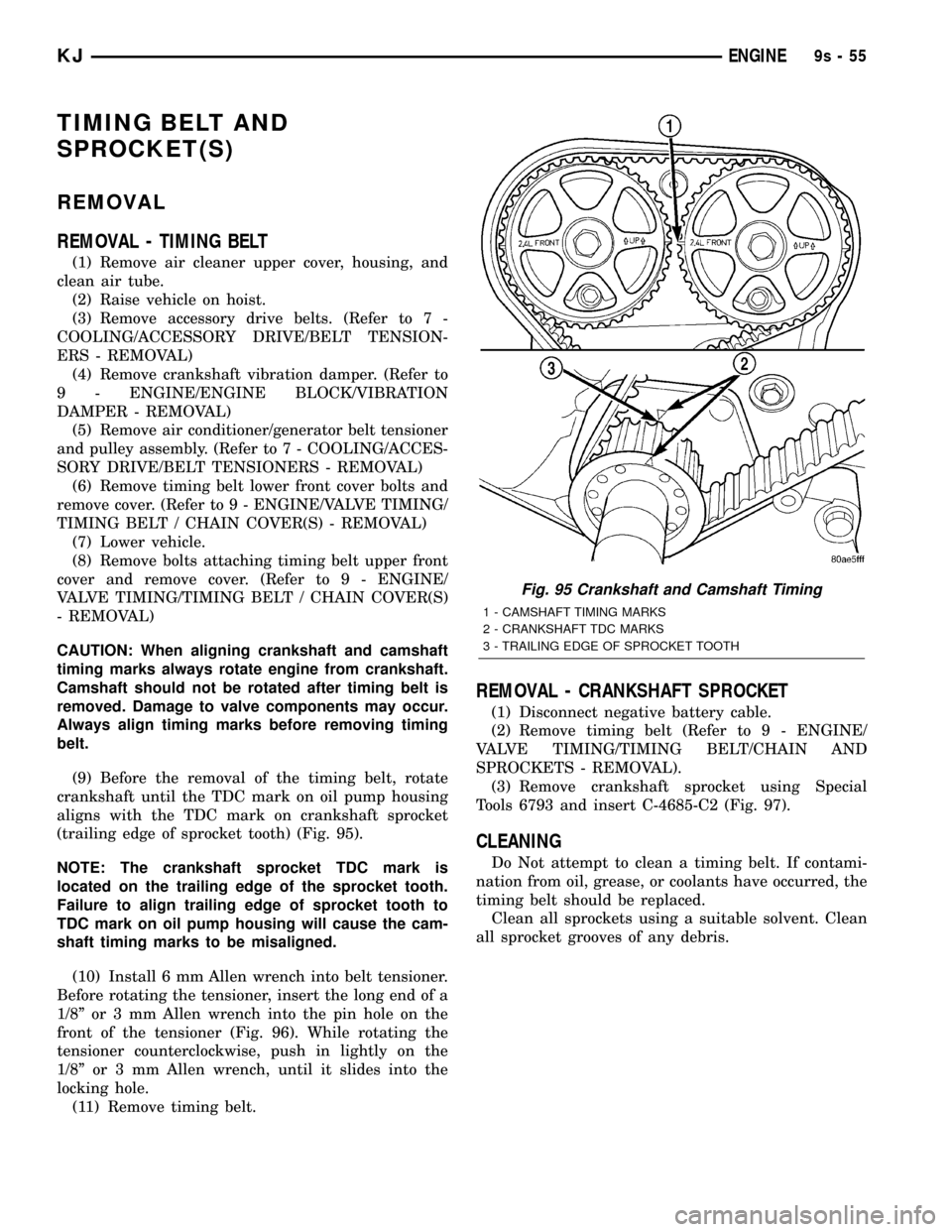
(trailing edge of sprocket tooth) (Fig. 95).
NOTE: The crankshaft sprocket TDC mark is
located on the trailing edge of the sprocket tooth.
Failure to align trailing edge of sprocket tooth to
TDC mark on oil pump housing will cause the cam-
shaft timing marks to be misaligned.
(10) Install 6 mm Allen wrench into belt tensioner.
Before rotating the tensioner, insert the long end of a
1/8º or 3 mm Allen wrench into the pin hole on the
front of the tensioner (Fig. 96). While rotating the
tensioner counterclockwise, push in lightly on the
1/8º or 3 mm Allen wrench, until it slides into the
locking hole.
(11) Remove timing belt.
REMOVAL - CRANKSHAFT SPROCKET
(1) Disconnect negative battery cable.
(2) Remove timing belt (Refer to 9 - ENGINE/
VALVE TIMING/TIMING BELT/CHAIN AND
SPROCKETS - REMOVAL).
(3) Remove crankshaft sprocket using Special
Tools 6793 and insert C-4685-C2 (Fig. 97).
CLEANING
Do Not attempt to clean a timing belt. If contami-
nation from oil, grease, or coolants have occurred, the
timing belt should be replaced.
Clean all sprockets using a suitable solvent. Clean
all sprocket grooves of any debris.
Fig. 95 Crankshaft and Camshaft Timing
1 - CAMSHAFT TIMING MARKS
2 - CRANKSHAFT TDC MARKS
3 - TRAILING EDGE OF SPROCKET TOOTH
KJENGINE9s-55
Page 1355 of 1803
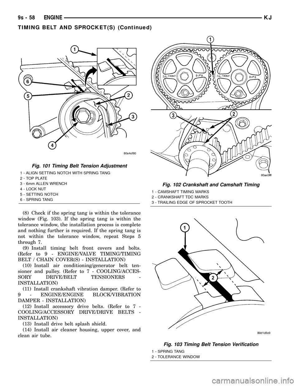
(8) Check if the spring tang is within the tolerance
window (Fig. 103). If the spring tang is within the
tolerance window, the installation process is complete
and nothing further is required. If the spring tang is
not within the tolerance window, repeat Steps 5
through 7.
(9) Install timing belt front covers and bolts.
(Refer to 9 - ENGINE/VALVE TIMING/TIMING
BELT / CHAIN COVER(S) - INSTALLATION)
(10) Install air conditioning/generator belt ten-
sioner and pulley. (Refer to 7 - COOLING/ACCES-
SORY DRIVE/BELT TENSIONERS -
INSTALLATION)
(11) Install crankshaft vibration damper. (Refer to
9 - ENGINE/ENGINE BLOCK/VIBRATION
DAMPER - INSTALLATION)
(12) Install accessory drive belts. (Refer to 7 -
COOLING/ACCESSORY DRIVE/DRIVE BELTS -
INSTALLATION)
(13) Install drive belt splash shield.
(14) Install air cleaner housing, upper cover, and
clean air tube.
Fig. 101 Timing Belt Tension Adjustment
1 - ALIGN SETTING NOTCH WITH SPRING TANG
2 - TOP PLATE
3 - 6mm ALLEN WRENCH
4 - LOCK NUT
5 - SETTING NOTCH
6 - SPRING TANG
Fig. 102 Crankshaft and Camshaft Timing
1 - CAMSHAFT TIMING MARKS
2 - CRANKSHAFT TDC MARKS
3 - TRAILING EDGE OF SPROCKET TOOTH
Fig. 103 Timing Belt Tension Verification
1 - SPRING TANG
2 - TOLERANCE WINDOW
9s - 58 ENGINEKJ
TIMING BELT AND SPROCKET(S) (Continued)
Page 1406 of 1803
(14) If fuel injectors are to be removed, refer to
Fuel Injector Removal/Installation.
INSTALLATION
2.4L Engine
(1) If fuel injectors are to be installed, refer to Fuel
Injector Removal/Installation.
(2) Clean out fuel injector machined bores in
intake manifold.
(3) Apply a small amount of engine oil to each fuel
injector o-ring. This will help in fuel rail installation.
(4) Position fuel rail/fuel injector assembly to
machined injector openings in intake manifold.
(5) Guide each injector into cylinder head. Be care-
ful not to tear injector o-rings.
(6) Push fuel rail down until fuel injectors have
bottomed on shoulders.
(7) Install 2 fuel rail mounting bolts and tighten.
Refer to torque specifications.
(8) Connect electrical connectors at all fuel injec-
tors. To install connector, refer to (Fig. 37). Push con-
nector onto injector (1) and then push and lock red
colored slider (2). Verify connector is locked to injec-
tor by lightly tugging on connector.
(9) Snap 2 injection wiring harness clips (Fig. 35)
into brackets.
(10) Connect 2 main engine harness connectors at
rear of intake manifold (Fig. 34).
(11) Tighten 5 intake manifold mounting bolts.
Refer to Engine Torque Specifications.
(12) Install PCV valve and hose.
(13) Install thermostat and radiator hose. Fill with
coolant. Refer to Cooling.
(14) Connect necessary vacuum lines to throttle
body.
(15) Connect fuel line latch clip and fuel line to
fuel rail. Refer to Quick-Connect Fittings.
(16) Install air duct to throttle body.
(17) Connect battery cable to battery.
(18) Start engine and check for leaks.
3.7L Engine
(1) If fuel injectors are to be installed, refer to Fuel
Injector Removal/Installation.
(2) Clean out fuel injector machined bores in
intake manifold.
(3) Apply a small amount of engine oil to each fuel
injector o-ring. This will help in fuel rail installation.
(4) Position fuel rail/fuel injector assembly to
machined injector openings in cylinder head.
(5) Guide each injector into cylinder head. Be care-
ful not to tear injector o-rings.
(6) Pushrightside of fuel rail down until fuel
injectors have bottomed on cylinder head shoulder.Pushleftfuel rail down until injectors have bot-
tomed on cylinder head shoulder.
(7) Install 4 fuel rail mounting bolts and tighten.
Refer to torque specifications.
(8) Install 6 ignition coils. Refer to Ignition Coil
Removal/Installation.
(9) Connect electrical connectors to throttle body.
(10) Connect electrical connectors at all fuel injec-
tors. To install connector, refer to (Fig. 37). Push con-
nector onto injector (1) and then push and lock red
colored slider (2). Verify connector is locked to injec-
tor by lightly tugging on connector.
(11) Connect necessary vacuum lines to throttle
body.
(12) Connect fuel line latch clip and fuel line to
fuel rail. Refer to Quick-Connect Fittings.
(13) Install air box to throttle body.
(14) Install air duct to air box.
(15) Connect battery cable to battery.
(16) Start engine and check for leaks.
FUEL TANK
DESCRIPTION
The fuel tank is constructed of a plastic material.
Its main functions are for fuel storage and for place-
ment of the fuel pump module, and certain ORVR
components.
OPERATION
All models pass a full 360 degree rollover test
without fuel leakage. To accomplish this, fuel and
vapor flow controls are required for all fuel tank con-
nections.
A check (control) valve is mounted into the top sec-
tion of the 2±piece fuel pump module. Refer to Fuel
Tank Check Valve for additional information.
An evaporation control system is connected to the
fuel tank to reduce emissions of fuel vapors into the
atmosphere. When fuel evaporates from the fuel
tank, vapors pass through vent hoses or tubes to a
charcoal canister where they are temporarily held.
When the engine is running, the vapors are drawn
into the intake manifold. Certain models are also
equipped with a self-diagnosing system using a Leak
Detection Pump (LDP) and/or an ORVR system.
Refer to Emission Control System for additional
information.
14 - 24 FUEL DELIVERYKJ
FUEL RAIL (Continued)
Page 1448 of 1803
NOTE: Power steering pumps have different pres-
sure rates and are not interchangeable with other
pumps.
STANDARD PROCEDURE - POWER STEERING
PUMP - INITIAL OPERATION
WARNING: THE FLUID LEVEL SHOULD BE
CHECKED WITH ENGINE OFF TO PREVENT INJURY
FROM MOVING COMPONENTS.
CAUTION: Use MOPAR Power Steering Fluid or
equivalent. Do not use automatic transmission fluid
and do not overfill.
Wipe filler cap clean, then check the fluid level.
The dipstick should indicateCOLDwhen the fluid is
at normal ambient temperature.
(1) Fill the pump fluid reservoir to the proper level
and let the fluid settle for at least two minutes.
(2) Raise the front wheels off the ground.
(3) Slowly turn the steering wheel right and left,
lightly contacting the wheel stops at least 20 times.
(4) Check the fluid level add if necessary.
(5) Lower the vehicle, start the engine and turn
the steering wheel slowly from lock to lock.
(6) Stop the engine and check the fluid level and
refill as required.
CAUTION: Do not run a vehicle with foamy fluid for
an extended period. This may cause pump damage.
(7) If the fluid is extremely foamy or milky look-
ing, allow the vehicle to stand a few minutes and
repeat the procedure.
(8) Add fluid if necessary. Repeat the above proce-
dure until the fluid level remains constant after run-
ning the engine.
REMOVAL
REMOVAL - 3.7L
(1) Siphon out as much power steering fluid as
possible.
(2) Remove the radiator cross member (Refer to 23
- BODY/EXTERIOR/RADIATOR CROSSMEMBER -
REMOVAL).
(3) Remove the engine cooling fan (Refer to 7 -
COOLING/ENGINE/RADIATOR FAN - REMOVAL).
(4) Remove the fan shroud
(5) Remove the serpentine drive belt (Refer to 7 -
COOLING/ACCESSORY DRIVE/DRIVE BELTS -
REMOVAL).
(6) Remove the power steering high pressure hose
at the pump.
(7) Remove the return hose at the pump.
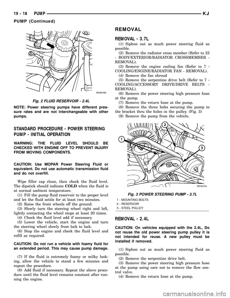
(8) Remove the three bolts securing the pump to
the bracket thru the holes in the pulley. (Fig. 3)
(9) Remove the pump from the vehicle.
REMOVAL - 2.4L
CAUTION: On vehicles equipped with the 2.4L, Do
not reuse the old power steering pump pulley it is
not intended for reuse. A new pulley must be
installed if removed.
(1) Siphon out as much power steering fluid as
possible.
(2) Remove the serpentine drive belt.
(3) Remove the power steering high pressure hose
at the pump using care not to remove the flow con-
trol valve.
(4) Remove the return hose at the pump.
Fig. 2 FLUID RESERVOIR - 2.4L
Fig. 3 POWER STEERING PUMP - 3.7L
1 - MOUNTING BOLTS
2 - RESERVOIR
3 - STEEL PULLEY
19 - 18 PUMPKJ
PUMP (Continued)
Page 1449 of 1803
(5) Remove the two nuts securing the wire loom
behind the pump bracket.
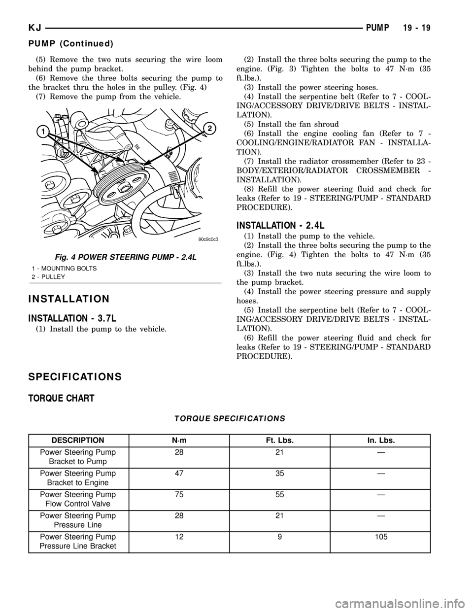
(6) Remove the three bolts securing the pump to
the bracket thru the holes in the pulley. (Fig. 4)
(7) Remove the pump from the vehicle.
INSTALLATION
INSTALLATION - 3.7L
(1) Install the pump to the vehicle.(2) Install the three bolts securing the pump to the
engine. (Fig. 3) Tighten the bolts to 47 N´m (35
ft.lbs.).
(3) Install the power steering hoses.
(4) Install the serpentine belt (Refer to 7 - COOL-
ING/ACCESSORY DRIVE/DRIVE BELTS - INSTAL-
LATION).
(5) Install the fan shroud
(6) Install the engine cooling fan (Refer to 7 -
COOLING/ENGINE/RADIATOR FAN - INSTALLA-
TION).
(7) Install the radiator crossmember (Refer to 23 -
BODY/EXTERIOR/RADIATOR CROSSMEMBER -
INSTALLATION).
(8) Refill the power steering fluid and check for
leaks (Refer to 19 - STEERING/PUMP - STANDARD
PROCEDURE).
INSTALLATION - 2.4L
(1) Install the pump to the vehicle.
(2) Install the three bolts securing the pump to the
engine. (Fig. 4) Tighten the bolts to 47 N´m (35
ft.lbs.).
(3) Install the two nuts securing the wire loom to
the pump bracket.
(4) Install the power steering pressure and supply
hoses.
(5) Install the serpentine belt (Refer to 7 - COOL-
ING/ACCESSORY DRIVE/DRIVE BELTS - INSTAL-
LATION).
(6) Refill the power steering fluid and check for
leaks (Refer to 19 - STEERING/PUMP - STANDARD
PROCEDURE).
SPECIFICATIONS
TORQUE CHART
TORQUE SPECIFICATIONS
DESCRIPTION N´m Ft. Lbs. In. Lbs.
Power Steering Pump
Bracket to Pump28 21 Ð
Power Steering Pump
Bracket to Engine47 35 Ð
Power Steering Pump
Flow Control Valve75 55 Ð
Power Steering Pump
Pressure Line28 21 Ð
Power Steering Pump
Pressure Line Bracket12 9 105
Fig. 4 POWER STEERING PUMP - 2.4L
1 - MOUNTING BOLTS
2 - PULLEY
KJPUMP 19 - 19
PUMP (Continued)