2002 JEEP LIBERTY exhaust flange torque
[x] Cancel search: exhaust flange torquePage 364 of 1803

INSTALLATION
2.4L 4±Cylinder
(1) Position starter into bellhousing and install 2
bolts. Refer to torque specifications.
(2) Install battery cable and nut to stud on starter
solenoid. Refer to torque specifications.
(3) Install solenoid wire connector to solenoid ter-
minal.
(4) Lower vehicle.
(5) Connect negative battery cable.
3.7L V-6
(1) Position front of starter towards rear of vehicle
with solenoid position rotated until it is located below
starter. Install starter by passing it between exhaust
pipe and transmission bellhousing.
(2) Position starter into bellhousing and install 2
bolts. Refer to torque specifications.
(3) Install battery cable and nut to stud on starter
solenoid. Refer to torque specifications.
(4) Install solenoid wire connector to solenoid ter-
minal.
(5) Position starter heat shield and install nut at
front of starter.
(6) Install 2 starter heat shield bolts at side of
starter.
(7) Install front propeller shaft.
(8) Install 2 flange bolts securing left exhaust
downpipe to crossover pipe.
(9) Lower vehicle.
(10) Connect negative battery cable.
STARTER MOTOR RELAY
DESCRIPTION
The starter relay is an electromechanical device
that switches battery current to the pull-in coil of the
starter solenoid when ignition switch is turned to
Start position. The starter relay is located in the
Power Distribution Center (PDC) in the engine com-
partment. See PDC cover for relay identification and
location.
The starter relay is a International Standards
Organization (ISO) relay. Relays conforming to ISO
specifications have common physical dimensions, cur-
rent capacities, terminal patterns, and terminal func-
tions.
The starter relay cannot be repaired or adjusted
and, if faulty or damaged, it must be replaced.
Fig. 11 STARTER ELECTRICAL CONNECTORS -
2.4L/3.7L
1 - BATERY CABLE NUT
2 - BATTERY CABLE
3 - SOLENOID CONNECTOR
4 - HEAT SHIELD
Fig. 12 STARTER - 3.7L
1-STARTER
2 - MOUNTING BOLTS (2)
KJSTARTING SYSTEM 8F - 41
STARTER MOTOR (Continued)
Page 1226 of 1803

NOTE: Recheck bolt torque for engine lift plate
before removing engine.
(30) Secure the left and right engine wiring har-
nesses away from engine.
(31) Raise vehicle.
(32) Disconnect oxygen sensor wiring.
(33) Disconnect crankshaft postion sensor.
(34) Disconnect the engine block heater power
cable, if equipped.
(35) Disconnect the front propshaft at the front
differential and secure out of way.
NOTE: It is necessary to disconnect the front prop-
shaft for access to the starter and left side exhaust
flange.
(36) Remove the starter.
(37) Remove the ground straps from the left and
right side of the block.
(38) Disconnect the right and left exhaust pipes at
the manifolds and from the crossover, and remove
from the vehicle.
NOTE: The exhaust clamps at the manifolds cannot
be reused. New clamps must be used or leaks may
occur.
NOTE: For manual transmission vehicles, the trans-
mission must be removed from the vehicle, before
the engine can be removed. The manual transmis-
sion will contact the floorpan before the engine
clears the motor mounts, so it must be removed.
(39) Remove the structural cover.
(40) Remove torque convertor bolts, and mark
location for reassembly.
(41) Remove transmission bellhousing to engine
bolts.
(42) Loosen left and right engine mount thru bolts.
NOTE: It is not necessary to completely remove
engine mount thru bolts, for engine removal.
(43) Lower the vehicle.
(44) Support the transmission with a suitable jack.
(45) Connect a suitable engine hoist to the engine
lift plate.
(46) Remove engine from vehicle.
INSTALLATION
(1) Position the engine in the vehicle.
(2) Install both left and right side engine mounts
onto engine.
(3) Raise the vehicle.(4) Install the transmission bellhousing to engine
mounting bolts. Tighten the bolts to 41 N´m (30ft.
lbs.).
(5) Tighten the engine mount thru bolts.
(6) Install the torque convertor bolts.
(7) Connect the ground straps on the left and right
side of the engine.
(8) Install the starter.
(9) Connect the crankshaft position sensor.
(10) Install the engine block heater power cable, if
equipped.
CAUTION: The structural cover requires a specific
torque sequence. Failure to follow this sequence
may cause severe damage to the cover.
(11) Install the structural cover.
NOTE: New clamps must be used on exhaust man-
ifold flanges. Failure to use new clamps may result
in exhaust leaks.
(12) Install the left and right exhaust pipes.
(13) Connect the left and right oxygen sensors.
(14) Lower vehicle.
(15) Remove the engine lift plate.
(16) Connect the knock sensors.
(17) Connect the engine to body ground straps at
the left side of the cowl.
(18) Install the intake manifold.
(19) Install the engine oil dipstick tube.
(20) Install the power brake booster vacuum hose.
(21) Install the breather hoses.
(22) Install the PCV hose.
(23) Install the fuel rail.
(24) Install the coil over plugs.
(25) Connect the engine wiring harness at the fol-
lowing points:
²Intake air temperature (IAT) sensor
²Fuel Injectors
²Throttle Position (TPS) Switch
²Idle Air Control (IAC) Motor
²Engine Oil Pressure Switch
²Engine Coolant Temperature (ECT) Sensor
²Manifold Absolute Pressure MAP) Sensor
²Camshaft Position (CMP) Sensor
²Coil Over Plugs
²Crankshaft Position Sensor
(26) Connect lower radiator hose.
(27) Connect upper radiator hose.
(28) Connect throttle and speed control cables.
(29) Install the heater hose assembly.
(30) Install coolant recovery bottle.
(31) Install the power steering pump.
(32) Install the generator.
(33) Install the A/C compressor.
(34) Install the drive belt.
KJENGINE - 3.7L 9 - 11
ENGINE - 3.7L (Continued)
Page 1286 of 1803

(1) Position the engine exhaust manifold and gas-
ket on the two studs located on the cylinder head.
Install conical washers and nuts on these studs.
(2) Install remaining conical washers. Starting at
the center arm and working outward, tighten the
bolts and nuts to 25 N´m (18 ft. lbs.) torque.
(3) Install the exhaust heat shields.
(4) Raise and support the vehicle.
CAUTION: Over tightening heat shield fasteners,
may cause shield to distort and/or crack.
(5) Assemble exhaust pipe to manifold and secure
with bolts, nuts and retainers. Tighten the bolts and
nuts to 34 N´m (25 ft. lbs.) torque.
LEFT EXHAUST MANIFOLD
CAUTION: If the studs came out with the nuts when
removing the engine exhaust manifold, install new
studs. Apply sealer on the coarse thread ends.
Water leaks may develop at the studs if this precau-
tion is not taken.
(1) Position the engine exhaust manifold and gas-
ket on the two studs located on the cylinder head.
Install conical washers and nuts on these studs.
(2) Install remaining conical washers. Starting at
the center arm and working outward, tighten the
bolts and nuts to 25 N´m (18 ft. lbs.) torque.
(3) Install the exhaust heat shields.
(4) Raise and support the vehicle.
CAUTION: Over tightening heat shield fasteners,
may cause shield to distort and/or crack.
(5) Assemble exhaust pipe to manifold and secure
with bolts, nuts and retainers. Tighten the bolts and
nuts to 34 N´m (25 ft. lbs.) torque.
VALVE TIMING
DESCRIPTION
The timing drive system has been designed to pro-
vide quiet performance and reliability to support a
non-free wheelingengine. Specifically the intake
valves are non-free wheeling and can be easily dam-
aged with forceful engine rotation if camshaft-to-
crankshaft timing is incorrect. The timing drive
system consists of a primary chain, two secondary
timing chain drives and a counterbalance shaft drive.
OPERATION
The primary timing chain is a single inverted tooth
chain type. The primary chain drives the large 40
tooth idler sprocket directly from a 20 tooth crank-shaft sprocket. Primary chain motion is controlled by
a pivoting leaf spring tensioner arm and a fixed
guide. The arm and the guide both use nylon plastic
wear faces for low friction and long wear. The pri-
mary chain receives oil splash lubrication from the
secondary chain drive and designed oil pump leak-
age. The idler sprocket assembly connects the pri-
mary chain drive, secondary chain drives, and the
counterbalance shaft. The idler sprocket assembly
consists of two integral 26 tooth sprockets a 40 tooth
sprocket and a helical gear that is press-fit to the
assembly. The spline joint for the 40 tooth sprocket is
a non ± serviceable press fit anti rattle type. A spiral
ring is installed on the outboard side of the fifty
tooth sprocket to prevent spline disengagement. The
idler sprocket assembly spins on a stationary idler
shaft. The idler shaft is a light press-fit into the cyl-
inder block. A large washer on the idler shaft bolt
and the rear flange of the idler shaft are used to con-
trol sprocket thrust movement. Pressurized oil is
routed through the center of the idler shaft to pro-
vide lubrication for the two bushings used in the
idler sprocket assembly.
There are two secondary drive chains, both are
roller type, one to drive the camshaft in each SOHC
cylinder head. There are no shaft speed changes in
the secondary chain drive system. Each secondary
chain drives a 26 tooth cam sprocket directly from
the 26 tooth sprocket on the idler sprocket assembly.
A fixed chain guide and a hydraulic oil damped ten-
sioner are used to maintain tension in each second-
ary chain system. The hydraulic tensioners for the
secondary chain systems are fed pressurized oil from
oil reservoir pockets in the block. Each tensioner
incorprates a controled leak path through a device
known as a vent disc located in the nose of the piston
to manage chain loads. Each tensioner also has a
mechanical ratchet system that limits chain slack if
the tensioner piston bleeds down after engine shut
down. The tensioner arms and guides also utilize
nylon wear faces for low friction and long wear. The
secondary timing chains receive lubrication from a
small orifice in the tensioners. This orifice is pro-
tected from clogging by a fine mesh screen which is
located on the back of the hydraulic tensioners.
STANDARD PROCEDURE
MEASURING TIMING CHAIN WEAR
NOTE: This procedure must be performed with the
timing chain cover removed.
(1) Remove the timing chain cover. Refer to Timing
Chain Cover in this section for procedure.
KJENGINE - 3.7L 9 - 71
EXHAUST MANIFOLD (Continued)
Page 1320 of 1803
(3) Install timing belt rear cover. (Refer to 9 -
ENGINE/VALVE TIMING/TIMING BELT / CHAIN
COVER(S) - INSTALLATION)
NOTE: Target ring tab should provide posative
snap-on fit on the camshaft.
(4) Install exhaust camshaft target ring with the
wordFRONTfacing forward.
(5) Install exhaust camshaft sensor.
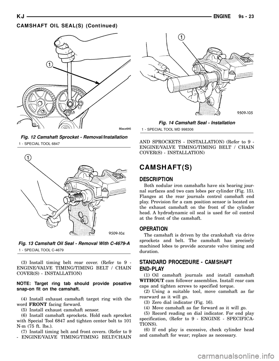
(6) Install camshaft sprockets. Hold each sprocket
with Special Tool 6847 and tighten center bolt to 101
N´m (75 ft. lbs.).
(7) Install timing belt and front covers. (Refer to 9
- ENGINE/VALVE TIMING/TIMING BELT/CHAINAND SPROCKETS - INSTALLATION) (Refer to 9 -
ENGINE/VALVE TIMING/TIMING BELT / CHAIN
COVER(S) - INSTALLATION)
CAMSHAFT(S)
DESCRIPTION
Both nodular iron camshafts have six bearing jour-
nal surfaces and two cam lobes per cylinder (Fig. 15).
Flanges at the rear journals control camshaft end
play. Provision for a cam position sensor is located on
the exhaust camshaft on the front of the cylinder
head. A hydrodynamic oil seal is used for oil control
at the front of the camshaft.
OPERATION
The camshaft is driven by the crankshaft via drive
sprockets and belt. The camshaft has precisely
machined lobes to provide accurate valve timing and
duration.
STANDARD PROCEDURE - CAMSHAFT
END-PLAY
(1) Oil camshaft journals and install camshaft
WITHOUTcam follower assemblies. Install rear cam
caps and tighten screws to specified torque.
(2) Using a suitable tool, move camshaft as far
rearward as it will go.
(3) Zero dial indicator (Fig. 16).
(4) Move camshaft as far forward as it will go.
(5) Record reading on dial indicator. For end play
specification, (Refer to 9 - ENGINE - SPECIFICA-
TIONS).
(6) If end play is excessive, check cylinder head
and camshaft for wear; replace as necessary.
Fig. 12 Camshaft Sprocket - Removal/Installation
1 - SPECIAL TOOL 6847
Fig. 13 Camshaft Oil Seal - Removal With C-4679-A
1 - SPECIAL TOOL C-4679
Fig. 14 Camshaft Seal - Installation
1 - SPECIAL TOOL MD 998306
KJENGINE9s-23
CAMSHAFT OIL SEAL(S) (Continued)
Page 1363 of 1803
DIAGNOSIS AND TESTING - EXHAUST SYSTEM
EXHAUST SYSTEM DIAGNOSIS CHART
CONDITION POSSIBLE CAUSE CORRECTION
EXCESSIVE EXHAUST NOISE OR
LEAKING EXHAUST GASES1. Leaks at pipe joints. 1. Tighten clamps/bolts to specified
torque at leaking joints.
2. Rusted or blown out muffler. 2. Replace muffler. Inspect exhaust
system.
3. Broken or rusted out exhaust
pipe.3. Replace exhaust pipe.
4. Exhaust pipe leaking at manifold
flange.4. Tighten/replace flange attaching
nuts/bolts.
5. Exhaust manifold cracked or
broken.5. Replace exhaust manifold.
6. Leak between exhaust manifold
and cylinder head.6. Tighten exhaust manifold to
cylinder head bolts.
7. Catalytic converter rusted or
blown out.7. Replace catalytic converter assy.
8. Restriction in exhaust system. 8. Remove restriction, if possible.
Replace restricted part if necessary.
CAUTION:
When servicing and replacing exhaust system components, disconnect the oxygen sensor connector(s). Allowing
the exhaust to hang by the oxygen sensor wires will damage the harness and/or sensor.
CATALYTIC CONVERTER
DESCRIPTION - CATALYTIC CONVERTER
WARNING: THE NORMAL OPERATING TEMPERA-
TURE OF THE EXHAUST SYSTEM IS VERY HIGH.
THEREFORE, NEVER WORK AROUND OR ATTEMPT
TO SERVICE ANY PART OF THE EXHAUST SYSTEM
UNTIL IT IS COOLED. SPECIAL CARE SHOULD BE
TAKEN WHEN WORKING NEAR THE CATALYTIC
CONVERTER. THE TEMPERATURE OF THE CON-
VERTER RISES TO A HIGH LEVEL AFTER A SHORT
PERIOD OF ENGINE OPERATION TIME.
CAUTION: DO NOT remove spark plug wires from
plugs or by any other means short out cylinders.
Failure of the catalytic converter can occur due to a
temperature increase caused by unburned fuel
passing through the converter.
The stainless steel catalytic converter body is
designed to last the life of the vehicle. Excessive heat
can result in bulging or other distortion, but exces-
sive heat will not be the fault of the converter. If
unburned fuel enters the converter, overheating may
occur. If a converter is heat-damaged, correct thecause of the damage at the same time the converter
is replaced. Also, inspect all other components of the
exhaust system for heat damage.
Unleaded gasoline must be used to avoid con-
taminating the catalyst core.
50 State emission vehicles incorporate two mini
catalytic converters located after the exhaust mani-
folds and before the inline catalytic converter.
REMOVAL
WARNING: IF TORCHES ARE USED WHEN WORK-
ING ON THE EXHAUST SYSTEM, DO NOT ALLOW
THE FLAME NEAR THE FUEL LINES.
(1) Raise and support the vehicle.
(2) Saturate the bolts and nuts with heat valve
lubricant. Allow 5 minutes for penetration.
(3) Remove the bolts from the crossover pipe to the
catalytic converter connection.
(4) Disconnect oxygen sensor wiring.
(5) Loosen the nuts from the clamp that hold the
catalytic converter to the exhaust pipe flange connec-
tion.
11 - 2 EXHAUST SYSTEMKJ
EXHAUST SYSTEM (Continued)
Page 1364 of 1803
NOTE: Do not remove nut from T-Bolt. Only remove
nut far enough, so that the T end can be removed
from the clamp.
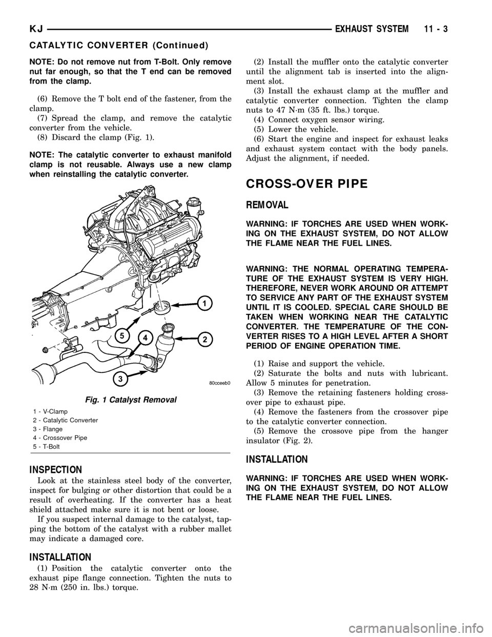
(6) Remove the T bolt end of the fastener, from the
clamp.
(7) Spread the clamp, and remove the catalytic
converter from the vehicle.
(8) Discard the clamp (Fig. 1).
NOTE: The catalytic converter to exhaust manifold
clamp is not reusable. Always use a new clamp
when reinstalling the catalytic converter.
INSPECTION
Look at the stainless steel body of the converter,
inspect for bulging or other distortion that could be a
result of overheating. If the converter has a heat
shield attached make sure it is not bent or loose.
If you suspect internal damage to the catalyst, tap-
ping the bottom of the catalyst with a rubber mallet
may indicate a damaged core.
INSTALLATION
(1) Position the catalytic converter onto the
exhaust pipe flange connection. Tighten the nuts to
28 N´m (250 in. lbs.) torque.(2) Install the muffler onto the catalytic converter
until the alignment tab is inserted into the align-
ment slot.
(3) Install the exhaust clamp at the muffler and
catalytic converter connection. Tighten the clamp
nuts to 47 N´m (35 ft. lbs.) torque.
(4) Connect oxygen sensor wiring.
(5) Lower the vehicle.
(6) Start the engine and inspect for exhaust leaks
and exhaust system contact with the body panels.
Adjust the alignment, if needed.
CROSS-OVER PIPE
REMOVAL
WARNING: IF TORCHES ARE USED WHEN WORK-
ING ON THE EXHAUST SYSTEM, DO NOT ALLOW
THE FLAME NEAR THE FUEL LINES.
WARNING: THE NORMAL OPERATING TEMPERA-
TURE OF THE EXHAUST SYSTEM IS VERY HIGH.
THEREFORE, NEVER WORK AROUND OR ATTEMPT
TO SERVICE ANY PART OF THE EXHAUST SYSTEM
UNTIL IT IS COOLED. SPECIAL CARE SHOULD BE
TAKEN WHEN WORKING NEAR THE CATALYTIC
CONVERTER. THE TEMPERATURE OF THE CON-
VERTER RISES TO A HIGH LEVEL AFTER A SHORT
PERIOD OF ENGINE OPERATION TIME.
(1) Raise and support the vehicle.
(2) Saturate the bolts and nuts with lubricant.
Allow 5 minutes for penetration.
(3) Remove the retaining fasteners holding cross-
over pipe to exhaust pipe.
(4) Remove the fasteners from the crossover pipe
to the catalytic converter connection.
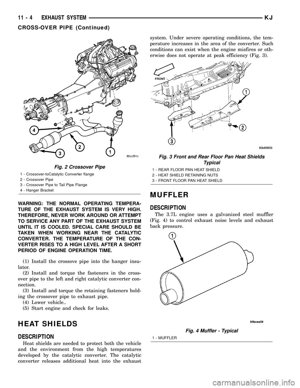
(5) Remove the crossove pipe from the hanger
insulator (Fig. 2).
INSTALLATION
WARNING: IF TORCHES ARE USED WHEN WORK-
ING ON THE EXHAUST SYSTEM, DO NOT ALLOW
THE FLAME NEAR THE FUEL LINES.
Fig. 1 Catalyst Removal
1 - V-Clamp
2 - Catalytic Converter
3 - Flange
4 - Crossover Pipe
5 - T-Bolt
KJEXHAUST SYSTEM 11 - 3
CATALYTIC CONVERTER (Continued)
Page 1365 of 1803
WARNING: THE NORMAL OPERATING TEMPERA-
TURE OF THE EXHAUST SYSTEM IS VERY HIGH.
THEREFORE, NEVER WORK AROUND OR ATTEMPT
TO SERVICE ANY PART OF THE EXHAUST SYSTEM
UNTIL IT IS COOLED. SPECIAL CARE SHOULD BE
TAKEN WHEN WORKING NEAR THE CATALYTIC
CONVERTER. THE TEMPERATURE OF THE CON-
VERTER RISES TO A HIGH LEVEL AFTER A SHORT
PERIOD OF ENGINE OPERATION TIME.
(1) Install the crossove pipe into the hanger insu-
lator.
(2) Install and torque the fasteners in the cross-
over pipe to the left and right catalytic converter con-
nection.
(3) Install and torque the retaining fasteners hold-
ing the crossover pipe to exhaust pipe.
(4) Lower vehicle..
(5) Start engine and check for leaks.
HEAT SHIELDS
DESCRIPTION
Heat shields are needed to protect both the vehicle
and the environment from the high temperatures
developed by the catalytic converter. The catalytic
converter releases additional heat into the exhaustsystem. Under severe operating conditions, the tem-
perature increases in the area of the converter. Such
conditions can exist when the engine misfires or oth-
erwise does not operate at peak efficiency (Fig. 3).
MUFFLER
DESCRIPTION
The 3.7L engine uses a galvanized steel muffler
(Fig. 4) to control exhaust noise levels and exhaust
back pressure.
Fig. 2 Crossover Pipe
1 - Crossover-toCatalytic Converter flange
2 - Crossover Pipe
3 - Crossover Pipe to Tail Pipe Flange
4 - Hanger Bracket
Fig. 3 Front and Rear Floor Pan Heat Shields
Typical
1 - REAR FLOOR PAN HEAT SHIELD
2 - HEAT SHIELD RETAINING NUTS
3 - FRONT FLOOR PAN HEAT SHIELD
Fig. 4 Muffler - Typical
1 - MUFFLER
11 - 4 EXHAUST SYSTEMKJ
CROSS-OVER PIPE (Continued)
Page 1369 of 1803
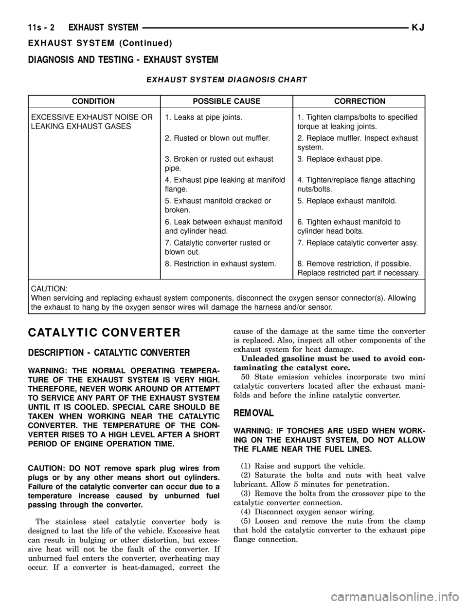
DIAGNOSIS AND TESTING - EXHAUST SYSTEM
EXHAUST SYSTEM DIAGNOSIS CHART
CONDITION POSSIBLE CAUSE CORRECTION
EXCESSIVE EXHAUST NOISE OR
LEAKING EXHAUST GASES1. Leaks at pipe joints. 1. Tighten clamps/bolts to specified
torque at leaking joints.
2. Rusted or blown out muffler. 2. Replace muffler. Inspect exhaust
system.
3. Broken or rusted out exhaust
pipe.3. Replace exhaust pipe.
4. Exhaust pipe leaking at manifold
flange.4. Tighten/replace flange attaching
nuts/bolts.
5. Exhaust manifold cracked or
broken.5. Replace exhaust manifold.
6. Leak between exhaust manifold
and cylinder head.6. Tighten exhaust manifold to
cylinder head bolts.
7. Catalytic converter rusted or
blown out.7. Replace catalytic converter assy.
8. Restriction in exhaust system. 8. Remove restriction, if possible.
Replace restricted part if necessary.
CAUTION:
When servicing and replacing exhaust system components, disconnect the oxygen sensor connector(s). Allowing
the exhaust to hang by the oxygen sensor wires will damage the harness and/or sensor.
CATALYTIC CONVERTER
DESCRIPTION - CATALYTIC CONVERTER
WARNING: THE NORMAL OPERATING TEMPERA-
TURE OF THE EXHAUST SYSTEM IS VERY HIGH.
THEREFORE, NEVER WORK AROUND OR ATTEMPT
TO SERVICE ANY PART OF THE EXHAUST SYSTEM
UNTIL IT IS COOLED. SPECIAL CARE SHOULD BE
TAKEN WHEN WORKING NEAR THE CATALYTIC
CONVERTER. THE TEMPERATURE OF THE CON-
VERTER RISES TO A HIGH LEVEL AFTER A SHORT
PERIOD OF ENGINE OPERATION TIME.
CAUTION: DO NOT remove spark plug wires from
plugs or by any other means short out cylinders.
Failure of the catalytic converter can occur due to a
temperature increase caused by unburned fuel
passing through the converter.
The stainless steel catalytic converter body is
designed to last the life of the vehicle. Excessive heat
can result in bulging or other distortion, but exces-
sive heat will not be the fault of the converter. If
unburned fuel enters the converter, overheating may
occur. If a converter is heat-damaged, correct thecause of the damage at the same time the converter
is replaced. Also, inspect all other components of the
exhaust system for heat damage.
Unleaded gasoline must be used to avoid con-
taminating the catalyst core.
50 State emission vehicles incorporate two mini
catalytic converters located after the exhaust mani-
folds and before the inline catalytic converter.
REMOVAL
WARNING: IF TORCHES ARE USED WHEN WORK-
ING ON THE EXHAUST SYSTEM, DO NOT ALLOW
THE FLAME NEAR THE FUEL LINES.
(1) Raise and support the vehicle.
(2) Saturate the bolts and nuts with heat valve
lubricant. Allow 5 minutes for penetration.
(3) Remove the bolts from the crossover pipe to the
catalytic converter connection.
(4) Disconnect oxygen sensor wiring.
(5) Loosen and remove the nuts from the clamp
that hold the catalytic converter to the exhaust pipe
flange connection.
11s - 2 EXHAUST SYSTEMKJ
EXHAUST SYSTEM (Continued)