2002 JEEP GRAND CHEROKEE engine oil fill tube
[x] Cancel search: engine oil fill tubePage 17 of 2199

DESCRIPTION - ENGINE OIL - DIESEL
ENGINES
Use only Diesel Engine Oil meeting standardMIL-
2104Cor API ClassificationCD or higherorCCML
D4, D5.
SAE VISCOSITY GRADE
CAUTION: Low viscosity oils must have the proper
API quality or the CCMC G5 designation.
To assure of properly formulated engine oils, it is
recommended that SAE Grade 10W-40 engine oils
that meet Chrysler material standard MS-6395, be
used. European Grade 10W-40 oils are also accept-
able.
Oils of the SAE 5W-40 or 8W-80 grade number are
preferred when minimum temperatures consistently
fall below -12ÉC.
OPERATION - AUTOMATIC TRANSMISSION
FLUID
The automatic transmission fluid is selected based
upon several qualities. The fluid must provide a high
level of protection for the internal components by
providing a lubricating film between adjacent metal
components. The fluid must also be thermally stable
so that it can maintain a consistent viscosity through
a large temperature range. If the viscosity stays con-
stant through the temperature range of operation,
transmission operation and shift feel will remain con-
sistent. Transmission fluid must also be a good con-
ductor of heat. The fluid must absorb heat from the
internal transmission components and transfer that
heat to the transmission case.
FLUID FILL/CHECK
LOCATIONS
INSPECTION - FLUID FILL/CHECK LOCATIONS
The fluid fill/check locations and lubrication points
are located in each applicable group.
MAINTENANCE SCHEDULES
DESCRIPTION
9Maintenance Schedule Information not included in
this section, is located in the appropriate Owner's
Manual.9
LIFT POINTS
STANDARD PROCEDURE - HOISTING AND
JACKING RECOMMENDATIONS
FLOOR JACK
When properly positioned, a floor jack can be used
to lift a WJ vehicle (Fig. 7). Support the vehicle in
the raised position with jack stands at the front and
rear ends of the frame rails.
CAUTION: Do not attempt to lift a vehicle with a
floor jack positioned under:
²An axle tube.
²Aluminum differential.
²A body side sill.
²A steering linkage component.
²A drive shaft.
²The engine or transmission oil pan.
²The fuel tank.
²A front suspension arm.
HOIST
A vehicle can be lifted with:
²A single-post, frame-contact hoist.
²A twin-post, chassis hoist.
²A ramp-type, drive-on hoist.
NOTE: When a frame-contact type hoist is used,
verify that the lifting pads are positioned properly
(Fig. 7).
WARNING: THE HOISTING AND JACK LIFTING
POINTS PROVIDED ARE FOR A COMPLETE VEHI-
CLE. WHEN A CHASSIS OR DRIVETRAIN COMPO-
NENT IS REMOVED FROM A VEHICLE, THE
CENTER OF GRAVITY IS ALTERED MAKING SOME
HOISTING CONDITIONS UNSTABLE. PROPERLY
SUPPORT OR SECURE VEHICLE TO HOISTING
DEVICE WHEN THESE CONDITIONS EXIST.
0 - 6 LUBRICATION & MAINTENANCEWJ
FLUID TYPES (Continued)
Page 409 of 2199

OPERATION
Battery voltage is supplied to the 8 ignition coils
from the ASD relay. The Powertrain Control Module
(PCM) opens and closes each ignition coil ground cir-
cuit at a determined time for ignition coil operation.
Base ignition timing is not adjustable.By con-
trolling the coil ground circuit, the PCM is able to set
the base timing and adjust the ignition timing
advance. This is done to meet changing engine oper-
ating conditions.
The ignition coil is not oil filled. The windings are
embedded in an epoxy compound. This provides heat
and vibration resistance that allows the ignition coil
to be mounted on the engine.
Because of coil design, spark plug cables (second-
ary cables) are not used.
REMOVAL
An individual ignition coil is used for each spark
plug (Fig. 18). The coil fits into machined holes in the
cylinder head. A mounting stud/nut secures each coil
to the top of the intake manifold (Fig. 19). The bot-
tom of the coil is equipped with a rubber boot to seal
the spark plug to the coil. Inside each rubber boot is
a spring. The spring is used for a mechanical contact
between the coil and the top of the spark plug. These
rubber boots and springs are a permanent part of the
coil and are not serviced separately. An o-ring (Fig.
18) is used to seal the coil at the opening into the cyl-
inder head.
(1) Depending on which coil is being removed, the
throttle body air intake tube or intake box may need
to be removed to gain access to coil.
(2) Disconnect electrical connector (Fig. 19) from
coil by pushing downward on release lock on top of
connector and pull connector from coil.
(3) Clean area at base of coil with compressed air
before removal.
(4) Remove coil mounting nut from mounting stud
(Fig. 19).
(5) Carefully pull up coil from cylinder head open-
ing with a slight twisting action.
(6) Remove coil from vehicle.
INSTALLATION
(1) Using compressed air, blow out any dirt or con-
taminants from around top of spark plug.
(2) Check condition of coil o-ring and replace as
necessary. To aid in coil installation, apply silicone to
coil o-ring.
(3) Position ignition coil into cylinder head opening
and push onto spark plug. Do this while guiding coil
base over mounting stud.
(4) Install mounting stud nut and tighten to 8 N´m
(70 in. lbs.) torque.(5) Connect electrical connector to coil by snapping
into position.
(6) If necessary, install throttle body air tube or
box.
Fig. 18 Ignition CoilÐ4.7L V±8
1 - O-RING
2 - IGNITION COIL
3 - ELECTRICAL CONNECTOR
Fig. 19 Ignition Coil
1 - IGNITION COIL
2 - COIL ELECTRICAL CONNECTOR
3 - COIL MOUNTING STUD/NUT
8I - 12 IGNITION CONTROLWJ
IGNITION COIL (Continued)
Page 1250 of 2199
CONDITION POSSIBLE CAUSES CORRECTION
3. Thin or diluted oil 3. Change oil to correct viscosity.
4. Excessive main bearing clearance 4. Measure bearings for correct
clearance. Repair as necessary
5. Excessive end play 5. Check crankshaft thrust bearing for
excessive wear on flanges
6. Crankshaft main journal out of
round or worn6. Grind journals or replace
crankshaft
7. Loose flywheel or torque converter 7. Inspect crankshaft, flexplate/
flywheel and bolts for damage.
Tighten to correct torque
LOW OIL PRESSURE 1. Low oil level 1. Check oil level and fill if necessary
2. Faulty oil pressure sending unit 2. Install new sending unit
3. Clogged oil filter 3. Install new oil filter
4. Worn oil pump 4. Replace oil pump assembly.
5. Thin or diluted oil 5. Change oil to correct viscosity.
6. Excessive bearing clearance 6. Measure bearings for correct
clearance
7. Oil pump relief valve stuck 7. Remove valve to inspect, clean
and reinstall
8. Oil pump suction tube loose,
broken, bent or clogged8. Inspect suction tube and clean or
replace if necessary
9. Oil pump cover warped or cracked 9. Install new oil pump
OIL LEAKS 1. Misaligned or deteriorated gaskets 1. Replace gasket
2. Loose fastener, broken or porous
metal part2. Tighten, repair or replace the part
3. Front or rear crankshaft oil seal
leaking3. Replace seal
4. Leaking oil gallery plug or cup
plug4. Remove and reseal threaded plug.
Replace cup style plug
EXCESSIVE OIL
CONSUMPTION OR SPARK
PLUGS OIL FOULED1. CCV System malfunction 1. (Refer to 25 - EMISSIONS
CONTROL/EVAPORATIVE
EMISSIONS - DESCRIPTION) for
correct operation
2. Defective valve stem seal(s) 2. Repair or replace seal(s)
3. Worn or broken piston rings 3. Hone cylinder bores. Install new
rings
4. Scuffed pistons/cylinder walls 4. Hone cylinder bores and replace
pistons as required
5. Carbon in oil control ring groove 5. Remove rings and de-carbon
piston
6. Worn valve guides 6. Inspect/replace valve guides as
necessary
7. Piston rings fitted too tightly in
grooves7. Remove rings and check ring end
gap and side clearance. Replace if
necessary
WJENGINE - 4.0L 9 - 7
ENGINE - 4.0L (Continued)
Page 1296 of 2199

(5) If the leak is not detected, very slowly turn the
crankshaft and watch for leakage. If a leak is
detected between the crankshaft and seal while
slowly turning the crankshaft, it is possible the
crankshaft seal surface is damaged. The seal area on
the crankshaft could have minor nicks or scratches
that can be polished out with emery cloth.
CAUTION: Use extreme caution when crankshaft
polishing is necessary to remove minor nicks and
scratches. The crankshaft seal flange is especially
machined to complement the function of the rear oil
seal.
(6) For bubbles that remain steady with shaft
rotation, no further inspection can be done until dis-
assembled.
OIL
STANDARD PROCEDURE - ENGINE OIL
SERVICE
ENGINE OIL CHANGE
Change engine oil at mileage and time intervals
described in Maintenance Schedules.
Run engine until achieving normal operating tem-
perature.
(1) Position the vehicle on a level surface and turn
engine off.
(2) Hoist and support vehicle on safety stands.
(3) Remove oil fill cap.
(4) Place a suitable drain pan under crankcase
drain.
(5) Remove drain plug from crankcase and allow
oil to drain into pan. Inspect drain plug threads for
stretching or other damage. Replace drain plug if
damaged.
(6) Install drain plug in crankcase.
(7) Replace engine oil filter. (Refer to 9 - ENGINE/
LUBRICATION/OIL FILTER - REMOVAL).
(8) Lower vehicle and fill crankcase with specified
type of engine oil (Refer to LUBRICATION & MAIN-
TENANCE/FLUID TYPES - DESCRIPTION) and
amount of engine oil (Refer to LUBRICATION &
MAINTENANCE - SPECIFICATIONS).
(9) Install oil fill cap.
(10) Start engine and inspect for leaks.
(11) Stop engine and inspect oil level. Refer to
CRANKCASE OIL LEVEL INSPECTION .
USED ENGINE OIL DISPOSAL
Care should be exercised when disposing used
engine oil after it has been drained from a vehicle
engine.
CRANKCASE OIL LEVEL INSPECTION
CAUTION: Do not overfill crankcase with engine oil,
oil foaming and oil pressure loss can result.
The engine oil level indicator (Dipstick) is located
at the right rear of the 4.0L engine. Inspect engine
oil level approximately every 800 kilometers (500
miles). Unless the engine has exhibited loss of oil
pressure, run the engine for about five minutes
before checking oil level. Checking engine oil level on
a cold engine is not accurate.
To ensure proper lubrication of an engine, the
engine oil must be maintained at an acceptable level.
The acceptable levels are indicated between the ADD
and SAFE marks on the engine oil dipstick (Fig. 74).
(1) Position vehicle on level surface.
(2) With engine OFF, allow approximately ten min-
utes for oil to settle to bottom of crankcase, remove
engine oil dipstick.
(3) Wipe dipstick clean.
(4) Install dipstick and verify it is seated in the
tube.
(5) Remove dipstick, with handle held above the
tip, take oil level reading (Fig. 74).
(6) Add oil only if level is below the ADD mark on
dipstick.
OIL FILTER
REMOVAL
CAUTION: Do not use oil filter with metric threads.
The proper oil filter has SAE type 3/4 X 16 threads.
An oil filter with metric threads can result in oil
leaks and engine failure.
Fig. 74 Engine Oil DipstickÐ4.0L Engine
1 - DIPSTICK
2 - ADD
3 - SAFE
WJENGINE - 4.0L 9 - 53
LUBRICATION (Continued)
Page 1299 of 2199

(9) Lower the engine until it is properly located on
the engine mounts.
(10) Install the through bolts and tighten the nuts.
(11) Lower the jack stand and remove the piece of
wood.
(12) Install the engine flywheel and transmission
torque converter housing access cover.
(13) Install the engine starter motor. (Refer to 8 -
ELECTRICAL/STARTING/STARTER MOTOR -
INSTALLATION).
(14) Connect the exhaust pipe to the hanger and to
the engine exhaust manifold.
(15) Install transmission oil cooling lines (if
equipped) and oxygen sensor wiring supports that
attach to the oil pan studs.
(16) Install the oil pan drain plug (Fig. 81).
Tighten the plug to 34 N´m (25 ft. lbs.) torque.
(17) Lower the vehicle.
(18) Connect negative cable to battery.
(19) Fill the oil pan with engine oil to the specified
level.
WARNING: USE EXTREME CAUTION WHEN THE
ENGINE IS OPERATING. DO NOT STAND IN A
DIRECT LINE WITH THE FAN. DO NOT PUT YOUR
HANDS NEAR THE PULLEYS, BELTS OR FAN. DO
NOT WEAR LOOSE CLOTHING.
(20) Start the engine and inspect for leaks.
ENGINE OIL PRESSURE
SENSOR
DESCRIPTION
The 3±wire, solid-state engine oil pressure sensor
(sending unit) is located in an engine oil pressure
gallery.
OPERATION
The oil pressure sensor uses three circuits. They
are:
²A 5±volt power supply from the Powertrain Con-
trol Module (PCM)
²A sensor ground through the PCM's sensor
return
²A signal to the PCM relating to engine oil pres-
sure
The oil pressure sensor has a 3±wire electrical
function very much like the Manifold Absolute Pres-
sure (MAP) sensor. Meaning different pressures
relate to different output voltages.
A 5±volt supply is sent to the sensor from the PCM
to power up the sensor. The sensor returns a voltage
signal back to the PCM relating to engine oil pres-
sure. This signal is then transferred (bussed) to theinstrument panel on either a CCD or PCI bus circuit
(depending on vehicle line) to operate the oil pressure
gauge and the check gauges lamp. Ground for the
sensor is provided by the PCM through a low-noise
sensor return.
OIL PUMP
REMOVAL
A gear-type oil pump is mounted at the underside
of the cylinder block opposite the No.4 main bearing.
(1) Drain the engine oil.
(2) Remove the oil pan (Refer to 9 - ENGINE/LU-
BRICATION/OIL PAN - REMOVAL).
(3) Remove the pump-to-cylinder block attaching
bolts. Remove the pump assembly with gasket (Fig.
82).
CAUTION: If the oil pump is not to be serviced, DO
NOT disturb position of oil inlet tube and strainer
assembly in pump body. If the tube is moved within
the pump body, a replacement tube and strainer
assembly must be installed to assure an airtight
seal.
Fig. 82 Oil Pump Assembly
1 - OIL FILTER ADAPTOR
2 - BLOCK
3 - GASKET
4 - OIL INLET TUBE
5 - OIL PUMP
6 - STRAINER ASSEMBLY
7 - ATTACHING BOLTS
9 - 56 ENGINE - 4.0LWJ
OIL PAN (Continued)
Page 1317 of 2199
²Camshaft Position (CMP) Sensor
²Coil Over Plugs
(10) Install generator (Refer to 8 - ELECTRICAL/
CHARGING/GENERATOR - INSTALLATION).
(11) Install radiator (Refer to 7 - COOLING/EN-
GINE/RADIATOR - INSTALLATION).
(12) Install A/C condenser (Refer to 24 - HEATING
& AIR CONDITIONING/PLUMBING/A/C CON-
DENSER - INSTALLATION).
(13) Connect radiator lower hose at the thermostat
housing.
(14) Connect the transmission oil cooler lines to
the radiator.
(15) Install A/C compressor. (Refer to 24 - HEAT-
ING & AIR CONDITIONING/PLUMBING/A/C COM-
PRESSOR - INSTALLATION).
(16) Install accessory drive belt (Refer to 7 -
COOLING/ACCESSORY DRIVE/DRIVE BELTS -
INSTALLATION) and radiator fan (Refer to 7 -
COOLING/ENGINE/RADIATOR FAN - INSTALLA-
TION).
(17) Install breathers, then connect tube to both
crankcase breathers (Fig. 5).
(18) Connect throttle and speed control cables.
(19) Install throttle body resonator assembly and
inlet hose.
(20) Raise vehicle.
(21) Connect two ground straps on the lower left
hand side of the engine and one ground strap on the
lower right side.
(22) Install torque converter bolts.
(23) Connect crankshaft position sensor (Fig. 4).
(24) Install starter.
(25) Install rubber splash shield.
CAUTION: The structural cover requires a specific
torque sequence. Failure to follow this sequence
may cause severe damage to the cover.
(26) Install structural cover (Refer to 9 - ENGINE/
ENGINE BLOCK/STRUCTURAL COVER - INSTAL-
LATION).
(27) Install exhaust crossover pipe.
(28) Install engine block heater power cable, If
equipped.
(29) Lower vehicle.
(30) Check and fill engine oil (Refer to LUBRICA-
TION & MAINTENANCE/FLUID TYPES - SPECIFI-
CATIONS).
(31) Recharge the A/C system (Refer to 24 - HEAT-
ING & AIR CONDITIONING/PLUMBING - STAN-
DARD PROCEDURE).
(32) Refill the engine cooling system (Refer to 7 -
COOLING - STANDARD PROCEDURE).
(33) Connect the battery negative cable.
(34) Start engine and check for leaks.SPECIFICATIONS
4.7L ENGINE
DESCRIPTION SPECIFICATION
GENERAL SPECIFICATIONS
Engine Type 90É SOHC V-8 16-Valve
Displacement 4.7 Liters / 4701cc
(287 Cubic Inches)
Bore 93.0 mm (3.66 in.)
Stroke 86.5 mm (3.40 in.)
Compression Ratio 9.0:1
Horsepower 235 BHP @ 4800 RPM
Torque 295 LB-FT @ 3200 RPM
Lead Cylinder #1 Left Bank
Firing Order 1-8-4-3-6-5-7-2
CYLINDER BLOCK
Cylinder Block Cast Iron
Bore Diameter 93.010 .0075 mm
(3.6619 0.0003 in.)
Out of Round (MAX) 0.076 mm (0.003 in.)
Taper (MAX) 0.051 mm (0.002 in.)
PISTONS
Material Aluminum Alloy
Diameter 92.975 mm (3.6605 in.)
Weight 367.5 grams (12.96 oz)
Ring Groove Diameter
No. 1 83.73 - 83.97 mm
(3.296 - 3.269 in.)
No. 2 82.833 - 83.033 mm
(3.261 - 3.310 in.)
No. 3 83.88 - 84.08 mm
(3.302 - 3.310 in.)
PISTON PINS
Type Pressed Fit
Clearance In Piston 0.010 - 0.019 mm
(0.0004 - 0.0008 in.)
Diameter 24.013 - 24.016 mm
(0.9454 - 0.9456 in.)
9 - 74 ENGINE - 4.7LWJ
ENGINE - 4.7L (Continued)
Page 1323 of 2199
DESCRIPTION N´m Ft. In.
Lbs. Lbs.
Exhaust Manifold Heat
ShieldÐNuts8Ð72
Then loosen 45É
FlexplateÐBolts 60 45 Ð
Engine Mount Bracket to
BlockÐBolts61 45 Ð
Rear Mount to
TransmissionÐBolts46 34 Ð
Generator MountingÐBolts
M10 Bolts 54 40 Ð
M8 Bolts 28 Ð 250
Intake ManifoldÐBolts 12 Ð 105
Refer to Procedure
for
Tightening Sequence
Oil PanÐBolts 15 Ð 130
Oil PanÐDrain Plug 34 25 Ð
Oil PumpÐBolts 28 Ð 250
Oil Pump CoverÐBolts 12 Ð 105
Oil Pickup TubeÐBolt and
Nut28 Ð 250
Oil Dipstick Tube to Engine
BlockÐBolt 15 Ð 130
Oil Fill TubeÐBolts 12 Ð 105
Timing Chain GuideÐBolts 28 Ð 250
Timing Chain Tensioner
ArmÐSpecial
Pin Bolt 17 Ð 150
Hydraulic TensionerÐBolts 28 Ð 250
Timing Chain Primary
TensionerÐBolts28 Ð 250
Timing Drive Idler SprocketÐ
Bolt34 25 Ð
Thermostat HousingÐBolts 13 Ð 115
Water PumpÐBolts 54 40 ÐSPECIAL TOOLS
4.7L ENGINE
Spanner Wrench 6958
Adapter Pins 8346
Engine Lifting Studs 8400
Engine Lift Fixture 8347
9 - 80 ENGINE - 4.7LWJ
ENGINE - 4.7L (Continued)
Page 1331 of 2199
(3) Position the cylinder head onto the cylinder
block. Make sure the cylinder head seats fully over
the locating dowels.
NOTE: The four smaller cylinder head mounting
bolts require sealant to be added to them before
installing. Failure to do so may cause leaks.
(4) Lubricate the cylinder head bolt threads with
clean engine oil and install the ten M11 bolts.
(5) Coat the four M8 cylinder head bolts with
MopartLock and Seal Adhesivethen install the
bolts.
NOTE: The cylinder head bolts are tightened using
an angle torque procedure, however, the bolts are
not a torque-to-yield design.
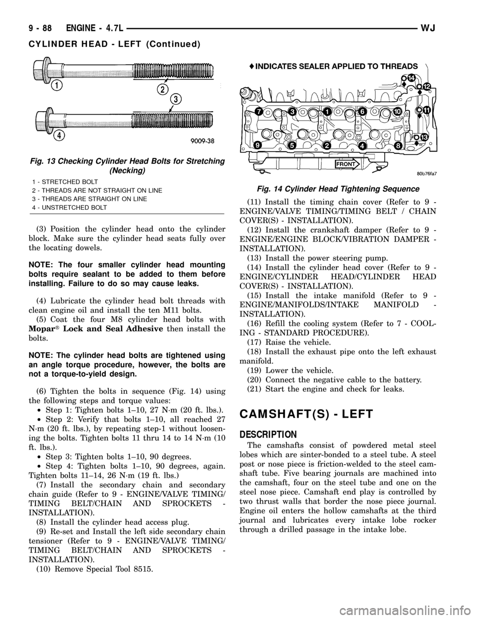
(6) Tighten the bolts in sequence (Fig. 14) using
the following steps and torque values:
²Step 1: Tighten bolts 1±10, 27 N´m (20 ft. lbs.).
²Step 2: Verify that bolts 1±10, all reached 27
N´m (20 ft. lbs.), by repeating step-1 without loosen-
ing the bolts. Tighten bolts 11 thru 14 to 14 N´m (10
ft. lbs.).
²Step 3: Tighten bolts 1±10, 90 degrees.
²Step 4: Tighten bolts 1±10, 90 degrees, again.
Tighten bolts 11±14, 26 N´m (19 ft. lbs.)
(7) Install the secondary chain and secondary
chain guide (Refer to 9 - ENGINE/VALVE TIMING/
TIMING BELT/CHAIN AND SPROCKETS -
INSTALLATION).
(8) Install the cylinder head access plug.
(9) Re-set and Install the left side secondary chain
tensioner (Refer to 9 - ENGINE/VALVE TIMING/
TIMING BELT/CHAIN AND SPROCKETS -
INSTALLATION).
(10) Remove Special Tool 8515.(11) Install the timing chain cover (Refer to 9 -
ENGINE/VALVE TIMING/TIMING BELT / CHAIN
COVER(S) - INSTALLATION).
(12) Install the crankshaft damper (Refer to 9 -
ENGINE/ENGINE BLOCK/VIBRATION DAMPER -
INSTALLATION).
(13) Install the power steering pump.
(14) Install the cylinder head cover (Refer to 9 -
ENGINE/CYLINDER HEAD/CYLINDER HEAD
COVER(S) - INSTALLATION).
(15) Install the intake manifold (Refer to 9 -
ENGINE/MANIFOLDS/INTAKE MANIFOLD -
INSTALLATION).
(16) Refill the cooling system (Refer to 7 - COOL-
ING - STANDARD PROCEDURE).
(17) Raise the vehicle.
(18) Install the exhaust pipe onto the left exhaust
manifold.
(19) Lower the vehicle.
(20) Connect the negative cable to the battery.
(21) Start the engine and check for leaks.
CAMSHAFT(S) - LEFT
DESCRIPTION
The camshafts consist of powdered metal steel
lobes which are sinter-bonded to a steel tube. A steel
post or nose piece is friction-welded to the steel cam-
shaft tube. Five bearing journals are machined into
the camshaft, four on the steel tube and one on the
steel nose piece. Camshaft end play is controlled by
two thrust walls that border the nose piece journal.
Engine oil enters the hollow camshafts at the third
journal and lubricates every intake lobe rocker
through a drilled passage in the intake lobe.
Fig. 13 Checking Cylinder Head Bolts for Stretching
(Necking)
1 - STRETCHED BOLT
2 - THREADS ARE NOT STRAIGHT ON LINE
3 - THREADS ARE STRAIGHT ON LINE
4 - UNSTRETCHED BOLTFig. 14 Cylinder Head Tightening Sequence
9 - 88 ENGINE - 4.7LWJ
CYLINDER HEAD - LEFT (Continued)