2002 JEEP GRAND CHEROKEE Transmission solenoid
[x] Cancel search: Transmission solenoidPage 233 of 2199
CONDITION POSSIBLE CAUSES CORRECTION
COOLANT LEVEL
CHANGES IN COOLANT
RESERVE/OVERFLOW
TANK. TEMPERATURE
GAUGE IS IN NORMAL
RANGE1. Level changes are to be expected
as coolant volume fluctuates with
engine temperature. If the level in
the tank was between the FULL and
ADD marks at normal operating
temperature, the level should return
to within that range after operation
at elevated temperatures.1. A normal condition. No repair is necessary.
FAN RUNS ALL THE
TIME1. Fan control sensors inoperative. 1. Check for DTC's. Verify sensor readings.
2. Fan control solenoid stuck9on9. 2. Check fan operation speeds. Refer to fan
speed operation table.
3. Fan control solenoid harness
damaged.3. Check for DTC 1499. Repair as required.
4. Transmission temperature too
high.4. Check for transmission over temp. DTC.
5. Engine coolant temperature too
high.5. (a) Check coolant level. Correct level as
required.
(b) Thermostat stuck. Replace thermostat.
(c) Water pump failed. Replace water pump.
(d) Coolant flow restricted. Clean radiator.
(e) Air flow over radiator obstructed.Remove
obstruction.
DIAGNOSIS AND TESTING - COOLING SYSTEM
LEAKS
ULTRAVIOLET LIGHT METHOD
A leak detection additive is available through the
parts department that can be added to cooling sys-
tem. The additive is highly visible under ultraviolet
light (black light). Pour one ounce of additive into
cooling system. Place heater control unit in HEAT
position. Start and operate engine until radiator
upper hose is warm to touch. Aim the commercially
available black light tool at components to be
checked. If leaks are present, black light will cause
additive to glow a bright green color.
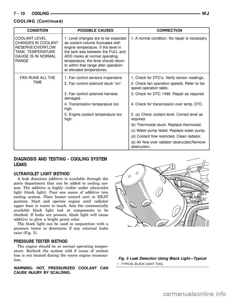
The black light can be used in conjunction with a
pressure tester to determine if any external leaks
exist (Fig. 5).
PRESSURE TESTER METHOD
The engine should be at normal operating temper-
ature. Recheck the system cold if cause of coolant
loss is not located during the warm engine examina-
tion.
WARNING: HOT, PRESSURIZED COOLANT CAN
CAUSE INJURY BY SCALDING.
Fig. 5 Leak Detection Using Black LightÐTypical
1 - TYPICAL BLACK LIGHT TOOL
7 - 10 COOLINGWJ
COOLING (Continued)
Page 251 of 2199
²Fan control valve
²Two stage G-rotor hydraulic drive
The hydraulic fan and drive is not serviceable.
Therefore any failure of the fan blade, hydraulic fan
drive or fan shroud requires replacement of the fan
module because the fan blade and hydraulic fan drive
are matched and balanced as a system and servicing
either separately would disrupt this balance.
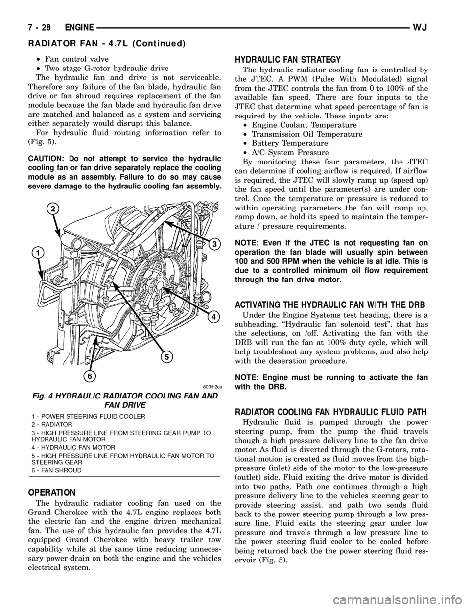
For hydraulic fluid routing information refer to
(Fig. 5).
CAUTION: Do not attempt to service the hydraulic
cooling fan or fan drive separately replace the cooling
module as an assembly. Failure to do so may cause
severe damage to the hydraulic cooling fan assembly.
OPERATION
The hydraulic radiator cooling fan used on the
Grand Cherokee with the 4.7L engine replaces both
the electric fan and the engine driven mechanical
fan. The use of this hydraulic fan provides the 4.7L
equipped Grand Cherokee with heavy trailer tow
capability while at the same time reducing unneces-
sary power drain on both the engine and the vehicles
electrical system.
HYDRAULIC FAN STRATEGY
The hydraulic radiator cooling fan is controlled by
the JTEC. A PWM (Pulse With Modulated) signal
from the JTEC controls the fan from 0 to 100% of the
available fan speed. There are four inputs to the
JTEC that determine what speed percentage of fan is
required by the vehicle. These inputs are:
²Engine Coolant Temperature
²Transmission Oil Temperature
²Battery Temperature
²A/C System Pressure
By monitoring these four parameters, the JTEC
can determine if cooling airflow is required. If airflow
is required, the JTEC will slowly ramp up (speed up)
the fan speed until the parameter(s) are under con-
trol. Once the temperature or pressure is reduced to
within operating parameters the fan will ramp up,
ramp down, or hold its speed to maintain the temper-
ature / pressure requirements.
NOTE: Even if the JTEC is not requesting fan on
operation the fan blade will usually spin between
100 and 500 RPM when the vehicle is at idle. This is
due to a controlled minimum oil flow requirement
through the fan drive motor.
ACTIVATING THE HYDRAULIC FAN WITH THE DRB
Under the Engine Systems test heading, there is a
subheading. ªHydraulic fan solenoid testº, that has
the selections, on /off. Activating the fan with the
DRB will run the fan at 100% duty cycle, which will
help troubleshoot any system problems, and also help
with the deaeration procedure.
NOTE: Engine must be running to activate the fan
with the DRB.
RADIATOR COOLING FAN HYDRAULIC FLUID PATH
Hydraulic fluid is pumped through the power
steering pump, from the pump the fluid travels
though a high pressure delivery line to the fan drive
motor. As fluid is diverted through the G-rotors, rota-
tional motion is created as fluid moves from the high-
pressure (inlet) side of the motor to the low-pressure
(outlet) side. Fluid exiting the drive motor is divided
into two paths. Path one continues through a high
pressure delivery line to the vehicles steering gear to
provide steering assist. and path two sends fluid
back to the power steering pump through a low pres-
sure line. Fluid exits the steering gear under low
pressure and travels through a low pressure line to
the power steering fluid cooler to be cooled before
being returned back the the power steering fluid res-
ervoir (Fig. 5).
Fig. 4 HYDRAULIC RADIATOR COOLING FAN AND
FAN DRIVE
1 - POWER STEERING FLUID COOLER
2 - RADIATOR
3 - HIGH PRESSURE LINE FROM STEERING GEAR PUMP TO
HYDRAULIC FAN MOTOR
4 - HYDRAULIC FAN MOTOR
5 - HIGH PRESSURE LINE FROM HYDRAULIC FAN MOTOR TO
STEERING GEAR
6 - FAN SHROUD
7 - 28 ENGINEWJ
RADIATOR FAN - 4.7L (Continued)
Page 266 of 2199

(4) Remove two radiator mounting bolts.
(5) Disconnect both transmission cooler lines from
radiator.
(6) Disconnect electrical connector for the fan con-
trol solenoid.
(7) Disconnect the power steering cooler line from
cooler and filter.
(8) Disconnect the radiator upper and lower hoses.
(9) Disconnect the overflow hose from radiator.
(10) Remove the air inlet duct at the grill.(11) The lower part of radiator is equipped with
two alignment dowel pins (Fig. 35). They are located
on the bottom of radiator tank and fit into rubber
grommets. These rubber grommets are pressed into
the radiator lower crossmember.
WARNING: THE AIR CONDITIONING SYSTEM (IF
EQUIPPED) IS UNDER A CONSTANT PRESSURE
EVEN WITH THE ENGINE OFF. REFER TO REFRIG-
ERANT WARNINGS IN, HEATING AND AIR CONDI-
TIONING BEFORE HANDLING ANY AIR
CONDITIONING COMPONENT.
NOTE: The radiator and radiator cooling fan can be
removed as an assembly. It is not necessary to
remove the cooling fan before removing or install-
ing the radiator.
(12) Disconnect the two high pressure fluid lines
at the hydraulic fan drive.
(13) Disconnect the low pressure return hose at
the hydraulic fan drive.
(14) Gently lift up and remove radiator from vehi-
cle. Be careful not to scrape the radiator fins against
any other component. Also be careful not to disturb
the air conditioning condenser (if equipped).
CLEANING
Clean radiator fins With the engine cold, apply cold
water and compressed air to the back (engine side) of
Fig. 32 Hose Clamp Tool - Typical
1 - HOSE CLAMP TOOL 6094
2 - HOSE CLAMP
Fig. 33 Clamp Number/Letter Location - Typical
1 - TYPICAL CONSTANT TENSION HOSE CLAMP
2 - CLAMP NUMBER/LETTER LOCATION
3 - TYPICAL HOSE
Fig. 34 Air Seals - Typical
1 - AIR DAM
2 - RADIATOR
3 - AIR DAM
4 - A/C CONDENSER
5 - AIR SEAL
WJENGINE 7 - 43
RADIATOR - 4.7L (Continued)
Page 267 of 2199

the radiator to flush the radiator and/or A/C con-
denser of debris.
INSPECTION
The radiator cooling fins should be checked for
damage or deterioration. Inspect cooling fins to make
sure they are not bent or crushed, these areas result
in reduced heat exchange causing the cooling system
to operate at higher temperatures. Inspect the plastic
end tanks for cracks, damage or leaks.
Inspect the radiator neck for damage or distortion.
INSTALLATION
CAUTION: Before installing the radiator or A/C con-
denser, be sure the radiator-to-body and radiator-to-
A/C condenser rubber air seals (Fig. 39) are
properly fastened to their original positions. These
are used at the top, bottom and sides of the radia-
tor and A/C condenser. To prevent overheating,
these seals must be installed to their original posi-
tions.
(1) Equipped with air conditioning: Gently lower
the radiator and fan shroud into the vehicle. Guide
the two radiator alignment dowels through the holes
in the rubber air seals first and then through the A/C
support brackets (Fig. 40). Continue to guide thealignment dowels into the rubber grommets located
in lower radiator crossmember. The holes in the
L-shaped brackets (located on bottom of A/C con-
denser) must be positioned between bottom of rubber
air seals and top of rubber grommets.
(2) Connect the radiator upper and lower hoses
and hose clamps to radiator.
CAUTION: The tangs on the hose clamps must be
positioned straight down.
(3) Install coolant reserve/overflow tank hose at
radiator.
(4) Connect both transmission cooler lines at the
radiator.
(5) Install both radiator mounting bolts.
(6) Install air inlet duct at grill.
(7) Attach electric connector for hydraulic fan con-
trol solenoid.
(8) Install the grill (Refer to 23 - BODY/EXTERI-
OR/GRILLE - INSTALLATION).
(9) Connect the two high pressure lines to the
hydraulic fan drive. Tighten
1¤2in. pressure line fit-
ting to 49 N´m (36 ft. lbs.). and the 3/8 in. pressure
line fitting to 29 N´m (21.5 ft. lbs.).
(10) Connect the low pressure hose to the hydrau-
lic fan drive. Position the spring clamp.
(11) Connect the power steering filter hoses to the
filter. Install new hose clamps.
(12) Rotate the fan blades (by hand) and check for
interference at fan shroud.
(13) Refill cooling system (Refer to 7 - COOLING -
STANDARD PROCEDURE).
(14) Refill the power steering reservoir and bleed
air from system (Refer to 19 - STEERING/PUMP -
STANDARD PROCEDURE).
(15) Connect battery cable at battery.
(16) Start and warm engine. Check for leaks.
RADIATOR - 4.0L
DESCRIPTION
All vehicles are equipped with a cross flow type
radiator with plastic side tanks (Fig. 36).
Plastic tanks, while stronger than brass, are sub-
ject to damage by impact, such as from tools or
wrenches. Handle radiator with care.
REMOVAL
WARNING: DO NOT REMOVE THE CYLINDER
BLOCK DRAIN PLUGS OR LOOSEN THE RADIATOR
DRAINCOCK WITH THE SYSTEM HOT AND UNDER
PRESSURE. SERIOUS BURNS FROM COOLANT
CAN OCCUR. REFER TO COOLING SYSTEM DRAIN-
ING.
Fig. 35 Radiator Alignment Dowels - Typical
1 - RADIATOR
2 - ALIGNMENT DOWEL
3 - RADIATOR LOWER ISOLATOR
4 - RADIATOR LOWER CROSSMEMBER
7 - 44 ENGINEWJ
RADIATOR - 4.7L (Continued)
Page 310 of 2199

ELECTRONIC CONTROL MODULES
TABLE OF CONTENTS
page page
ELECTRONIC CONTROL MODULES
STANDARD PROCEDURE - PCM/SKIM
PROGRAMMING.......................1
ADJUSTABLE PEDALS MODULE
REMOVAL.............................2
INSTALLATION..........................3
BODY CONTROL MODULE
DESCRIPTION..........................3
OPERATION............................3
DIAGNOSIS AND TESTING - BODY CONTROL
MODULE.............................4
REMOVAL.............................5
INSTALLATION..........................5
COMMUNICATION
DESCRIPTION..........................6
OPERATION............................6
CONTROLLER ANTILOCK BRAKE
DESCRIPTION..........................6
OPERATION............................6
REMOVAL.............................7
INSTALLATION..........................7
DATA LINK CONNECTOR
DESCRIPTION - DATA LINK CONNECTOR.....7
OPERATION - DATA LINK CONNECTOR......7
DOOR MODULE
DESCRIPTION..........................7
OPERATION............................9
DIAGNOSIS AND TESTING - DOOR MODULE . 10
REMOVAL.............................10
INSTALLATION.........................10
MEMORY HEATED SEAT/MIRROR MODULE
DESCRIPTION.........................10OPERATION...........................11
DIAGNOSIS AND TESTING
DIAGNOSIS AND TESTING - HEATED SEAT
MODULE............................11
REMOVAL.............................11
INSTALLATION.........................12
POWERTRAIN CONTROL MODULE
DESCRIPTION
DESCRIPTION - PCM..................12
MODES OF OPERATION................12
DESCRIPTION - 5 VOLT SUPPLIES.......14
DESCRIPTION - IGNITION CIRCUIT SENSE . 14
DESCRIPTION - POWER GROUNDS......15
DESCRIPTION - SENSOR RETURN.......15
OPERATION
OPERATION - PCM....................15
OPERATION - 5 VOLT SUPPLIES.........16
OPERATION - IGNITION CIRCUIT SENSE . . . 16
REMOVAL.............................16
INSTALLATION.........................17
SENTRY KEY IMMOBILIZER MODULE
DESCRIPTION.........................17
OPERATION...........................17
REMOVAL.............................18
INSTALLATION.........................19
TRANSMISSION CONTROL MODULE
DESCRIPTION.........................19
OPERATION...........................19
STANDARD PROCEDURE
STANDARD PROCEDURE - TCM QUICK
LEARN..............................22
ELECTRONIC CONTROL
MODULES
STANDARD PROCEDURE - PCM/SKIM
PROGRAMMING
NOTE: Before replacing the PCM, be sure to check
the related component/circuit integrity for failures
not detected due to a double fault in the circuit.
Most PCM failures are caused by internal compo-
nent failures (i.e. relays and solenoids) and shorted
circuits (i.e. pull-ups, drivers, and switched cir-
cuits). These failures are difficult to detect when a
double fault has occurred and only one DTC has
been set.When a PCM (JTEC) and the SKIM are replaced
at the same time, perform the following steps in
order:
(1) Program the new PCM (JTEC).
(2) Program the new SKIM.
(3) Replace all ignition keys and program them to
the new SKIM.
PROGRAMMING THE PCM (JTEC)
The SKIS Secret Key is an ID code that is unique
to each SKIM. This code is programmed and stored
in the SKIM, the PCM, and the ignition key tran-
sponder chip(s). When replacing the PCM, it is nec-
essary to program the secret key into the new PCM
using the DRBIIItscan tool. Perform the following
steps to program the secret key into the PCM.
WJELECTRONIC CONTROL MODULES 8E - 1
Page 324 of 2199

DESCRIPTION - POWER GROUNDS
The Powertrain Control Module (PCM) has 2 main
grounds. Both of these grounds are referred to as
power grounds. All of the high-current, noisy, electri-
cal devices are connected to these grounds as well as
all of the sensor returns. The sensor return comes
into the sensor return circuit, passes through noise
suppression, and is then connected to the power
ground.
The power ground is used to control ground cir-
cuits for the following PCM loads:
²Generator field winding
²Fuel injectors
²Ignition coil(s)
²Certain relays/solenoids
²Certain sensors
DESCRIPTION - SENSOR RETURN
The Sensor Return circuits are internal to the Pow-
ertrain Control Module (PCM).
Sensor Return provides a low±noise ground refer-
ence for all engine control system sensors. Refer to
Power Grounds for more information.
OPERATION
OPERATION - PCM
(1) Also refer to Modes of Operation.
The PCM operates the fuel system. The PCM is a
pre-programmed, triple microprocessor digital com-
puter. It regulates ignition timing, air-fuel ratio,
emission control devices, charging system, certain
transmission features, speed control, air conditioning
compressor clutch engagement and idle speed. The
PCM can adapt its programming to meet changing
operating conditions.
The PCM receives input signals from various
switches and sensors. Based on these inputs, the
PCM regulates various engine and vehicle operations
through different system components. These compo-
nents are referred to as Powertrain Control Module
(PCM) Outputs. The sensors and switches that pro-
vide inputs to the PCM are considered Powertrain
Control Module (PCM) Inputs.
The PCM adjusts ignition timing based upon
inputs it receives from sensors that react to: engine
rpm, manifold absolute pressure, engine coolant tem-
perature, throttle position, transmission gear selec-
tion (automatic transmission), vehicle speed and the
brake switch.
The PCM adjusts idle speed based on inputs it
receives from sensors that react to: throttle position,
vehicle speed, transmission gear selection, engine
coolant temperature and from inputs it receives from
the air conditioning clutch switch and brake switch.Based on inputs that it receives, the PCM adjusts
ignition coil dwell. The PCM also adjusts the gener-
ator charge rate through control of the generator
field and provides speed control operation.
NOTE: PCM Inputs:
²A/C request
²Auto shutdown (ASD) sense
²Battery temperature
²Battery voltage
²Brake switch
²J1850 bus circuits
²Camshaft position sensor signal
²Crankshaft position sensor
²Data link connections for DRB scan tool
²Engine coolant temperature sensor
²Five volts (primary)
²Five volts (secondary)
²Fuel level
²Generator (battery voltage) output
²Ignition circuit sense (ignition switch in on/off/
crank/run position)
²Intake manifold air temperature sensor
²Leak detection pump (switch) sense (if equipped)
²Manifold absolute pressure (MAP) sensor
²Oil pressure
²Overdrive/override switch
²Oxygen sensors
²Park/neutral switch (auto. trans. only)
²Power ground
²Sensor return
²Signal ground
²Speed control multiplexed single wire input
²Throttle position sensor
²Transmission governor pressure sensor
²Transmission temperature sensor
²Vehicle speed (from ABS module)
NOTE: PCM Outputs:
²A/C clutch relay
²Auto shutdown (ASD) relay
²J1850 (+/-) circuits for: speedometer, voltmeter,
fuel gauge, oil pressure gauge/lamp, engine temp.
gauge and speed control warn. lamp
²Data link connection for DRBIIItscan tool
²EGR valve control solenoid (if equipped)
²EVAP canister purge solenoid
²Fuel injectors
²Fuel pump relay
²Generator field driver (-)
²Generator field driver (+)
²Generator lamp (if equipped)
²Idle air control (IAC) motor
²Ignition coil
²Leak detection pump
WJELECTRONIC CONTROL MODULES 8E - 15
POWERTRAIN CONTROL MODULE (Continued)
Page 325 of 2199

²Malfunction indicator lamp (Check engine lamp).
Driven through J1850 circuits.
²Overdrive indicator lamp (if equipped). Driven
through J1850 circuits.
²Oxygen sensor heater relays (if equipped).
²Radiator cooling fan relay (pulse width modu-
lated)
²Speed control source
²Speed control vacuum solenoid
²Speed control vent solenoid
²Tachometer (if equipped). Driven through J1850
circuits.
²Transmission convertor clutch circuit
²Transmission 3±4 shift solenoid
²Transmission relay
²Transmission temperature lamp (if equipped)
²Transmission variable force solenoid
OPERATION - 5 VOLT SUPPLIES
Primary 5±volt supply:
²supplies the required 5 volt power source to the
Crankshaft Position (CKP) sensor.
²supplies the required 5 volt power source to the
Camshaft Position (CMP) sensor.
²supplies a reference voltage for the Manifold
Absolute Pressure (MAP) sensor.
²supplies a reference voltage for the Throttle
Position Sensor (TPS) sensor.
Secondary 5±volt supply:
²supplies the required 5 volt power source to the
oil pressure sensor.
²supplies the required 5 volt power source for the
Vehicle Speed Sensor (VSS) (if equipped).
²supplies the 5 volt power source to the transmis-
sion pressure sensor (if equipped with an RE auto-
matic transmission).
OPERATION - IGNITION CIRCUIT SENSE
The ignition circuit sense input tells the PCM the
ignition switch has energized the ignition circuit.
Battery voltage is also supplied to the PCM
through the ignition switch when the ignition is in
the RUN or START position. This is referred to as
the9ignition sense9circuit and is used to9wake up9
the PCM.
REMOVAL
USE THE DRBIIItSCAN TOOL TO REPRO-
GRAM THE NEW POWERTRAIN CONTROL
MODULE (PCM) WITH THE VEHICLES ORIGI-
NAL IDENTIFICATION NUMBER (VIN) AND
THE VEHICLES ORIGINAL MILEAGE. IF THIS
STEP IS NOT DONE, A DIAGNOSTIC TROUBLE
CODE (DTC) MAY BE SET.
The PCM is located on the cowl panel in right/rear
side of engine compartment (Fig. 12).The PCM is located on the cowl panel in right/rear
side of engine compartment (Fig. 12).
To avoid possible voltage spike damage to PCM,
ignition key must be off, and negative battery cable
must be disconnected before unplugging PCM connec-
tors.
(1) Disconnect negative battery cable at battery.
Fig. 12 Powertrain Control Module (PCM) Location
1 - PCM
2 - COOLANT TANK
Fig. 13 Powertrain Control Module (PCM) 32±Way
Connectors
1 - 3 32±WAY CONNECTORS
2 - PCM/BRACKET ASSEMBLY
3 - BRACKET NUTS (3)
8E - 16 ELECTRONIC CONTROL MODULESWJ
POWERTRAIN CONTROL MODULE (Continued)
Page 329 of 2199

²Pressure Switches
²Transmission Temperature Sensor
²Input Shaft Speed Sensor
²Output Shaft Speed Sensor
²Line Pressure Sensor
Some examples ofindirect inputsto the TCM
are:
²Engine/Body Identification
²Manifold Pressure
²Target Idle
²Torque Reduction Confirmation
²Engine Coolant Temperature
²Ambient/Battery Temperature
²DRBtScan Tool Communication
Based on the information received from these var-
ious inputs, the TCM determines the appropriate
shift schedule and shift points, depending on the
present operating conditions and driver demand.
This is possible through the control of various direct
and indirect outputs.
Some examples of TCMdirect outputsare:
²Transmission Control Relay
²Solenoids
²Torque Reduction Request
Some examples of TCMindirect outputsare:
²Transmission Temperature (to PCM)
²PRNDL Position (to BCM)
In addition to monitoring inputs and controlling
outputs, the TCM has other important responsibili-
ties and functions:
²Storing and maintaining Clutch Volume Indexes
(CVI)
²Storing and selecting appropriate Shift Sched-
ules
²System self-diagnostics
²Diagnostic capabilities (with DRBtscan tool)
NOTE: If the TCM has been replaced, the ªQuick
Learn Procedureº must be performed. (Refer to 8 -
ELECTRICAL/ELECTRONIC CONTROL MODULES/
TRANSMISSION CONTROL MODULE - STANDARD
PROCEDURE)
BATTERY FEED
A fused, direct battery feed to the TCM is used for
continuous power. This battery voltage is necessary
to retain adaptive learn values in the TCM's RAM
(Random Access Memory). When the battery (B+) is
disconnected, this memory is lost. When the battery
(B+) is restored, this memory loss is detected by the
TCM and a Diagnostic Trouble Code (DTC) is set.
CLUTCH VOLUME INDEXES (CVI)
An important function of the TCM is to monitor
Clutch Volume Indexes (CVI). CVIs represent the vol-
ume of fluid needed to compress a clutch pack.The TCM monitors gear ratio changes by monitor-
ing the Input and Output Speed Sensors. The Input,
or Turbine Speed Sensor sends an electrical signal to
the TCM that represents input shaft rpm. The Out-
put Speed Sensor provides the TCM with output
shaft speed information.
By comparing the two inputs, the TCM can deter-
mine transmission gear position. This is important to
the CVI calculation because the TCM determines
CVIs by monitoring how long it takes for a gear
change to occur (Fig. 18).
Gear ratios can be determined by using the
DRBIIItScan Tool and reading the Input/Output
Speed Sensor values in the ªMonitorsº display. Gear
ratio can be obtained by dividing the Input Speed
Sensor value by the Output Speed Sensor value.
The gear ratio changes as clutches are applied and
released. By monitoring the length of time it takes
for the gear ratio to change following a shift request,
the TCM can determine the volume of fluid used to
apply or release a friction element.
The volume of transmission fluid needed to apply
the friction elements are continuously updated for
adaptive controls. As friction material wears, the vol-
ume of fluid need to apply the element increases.
Fig. 18 Example of CVI Calculation
1 - OUTPUT SPEED SENSOR
2 - OUTPUT SHAFT
3 - CLUTCH PACK
4 - SEPARATOR PLATE
5 - FRICTION DISCS
6 - INPUT SHAFT
7 - INPUT SPEED SENSOR
8 - PISTON AND SEAL
8E - 20 ELECTRONIC CONTROL MODULESWJ
TRANSMISSION CONTROL MODULE (Continued)