2002 JEEP GRAND CHEROKEE Fan clutch
[x] Cancel search: Fan clutchPage 230 of 2199

CONDITION POSSIBLE CAUSES CORRECTION
17. Viscous fan drive not operating
properly.17. Check fan drive operation and replace as
necessary. (Refer to 7 - COOLING/ENGINE/
FAN DRIVE VISCOUS CLUTCH -
DIAGNOSIS AND TESTING).
18. Cylinder head gasket leaking. 18. Check for cylinder head gasket leaks.
(Refer to 7 - COOLING - DIAGNOSIS AND
TESTING). For repair, (Refer to 9 -
ENGINE/CYLINDER HEAD - REMOVAL).
19. Heater core leaking. 19. Check heater core for leaks. (Refer to 24
- HEATING & AIR CONDITIONING/
PLUMBING/HEATER CORE - REMOVAL).
Repair as necessary.
20. Hydraulic fan speed too low or
inopertive.20. Check for
DTC code.
Check fan operation speeds.
Refer to fan speed operation table.
Low power steering pump output. Refer to
power steering pump diagnosis - 4.7L engine.
TEMPERATURE GAUGE
READING IS
INCONSISTENT
(FLUCTUATES, CYCLES
OR IS ERRATIC)1. During cold weather operation,
with the heater blower in the high
position, the gauge reading may
drop slightly.1. A normal condition. No correction is
necessary.
2. Temperature gauge or engine
mounted gauge sensor defective or
shorted. Also, corroded or loose
wiring in this circuit.2. Check operation of gauge and repair if
necessary. Refer to Group 8J, Instrument
cluster.
3. Gauge reading rises when vehicle
is brought to a stop after heavy use
(engine still running)3. A normal condition. No correction is
necessary. Gauge should return to normal
range after vehicle is driven.
4. Gauge reading high after
re-starting a warmed up (hot)
engine.4. A normal condition. No correction is
necessary. The gauge should return to
normal range after a few minutes of engine
operation.
5. Coolant level low in radiator (air
will build up in the cooling system
causing the thermostat to open late).5. Check and correct coolant leaks. (Refer to
7 - COOLING - DIAGNOSIS AND TESTING).
6. Cylinder head gasket leaking
allowing exhaust gas to enter
cooling system causing a thermostat
to open late.6. (a) Check for cylinder head gasket leaks.
(Refer to 7 - COOLING - DIAGNOSIS AND
TESTING).
(b) Check for coolant in the engine oil.
Inspect for white steam emitting from the
exhaust system. Repair as necessary.
WJCOOLING 7 - 7
COOLING (Continued)
Page 247 of 2199

ENGINE
TABLE OF CONTENTS
page page
COOLANT
DESCRIPTION
DESCRIPTION - ENGINE COOLANT.......25
DESCRIPTION - HOAT COOLANT.........25
OPERATION...........................26
COOLANT LEVEL SENSOR
REMOVAL.............................26
INSTALLATION.........................26
COOLANT RECOVERY PRESS CONTAINER
DESCRIPTION.........................27
RADIATOR FAN - 4.7L
DESCRIPTION.........................27
OPERATION...........................28
REMOVAL.............................29
CLEANING............................30
INSTALLATION.........................30
RADIATOR FAN - 4.0L
DESCRIPTION.........................31
REMOVAL.............................31
CLEANING............................32
INSPECTION..........................32
INSTALLATION.........................32
ENGINE BLOCK HEATER
DESCRIPTION
DESCRIPTIONÐ4.7L ENGINE............32
DESCRIPTIONÐ4.0L ENGINE............32
OPERATION...........................33
DIAGNOSIS AND TESTINGÐENGINE BLOCK
HEATER ............................33
REMOVAL
REMOVALÐ4.7L ENGINE...............33
REMOVALÐ4.0L ENGINE...............34
INSTALLATION
INSTALLATIONÐ4.7L ENGINE...........34
INSTALLATIONÐ4.0L ENGINE...........34
ENGINE COOLANT TEMP SENSOR
DESCRIPTION.........................35
OPERATION...........................35
REMOVAL
REMOVALÐ4.0L ENGINE...............35
REMOVALÐ4.7L ENGINE...............36
INSTALLATION
INSTALLATIONÐ4.0L ENGINE...........36
INSTALLATIONÐ4.7L ENGINE...........36
ENGINE COOLANT THERMOSTAT
DESCRIPTION
DESCRIPTIONÐ4.7L ENGINE............36
DESCRIPTIONÐ4.0L ENGINE............37
OPERATION...........................37DIAGNOSIS AND TESTINGÐTHERMOSTAT . . . 37
REMOVAL
REMOVALÐ4.0L ENGINE...............38
REMOVALÐ4.7L ENGINE...............38
INSTALLATION
INSTALLATIONÐ4.0L ENGINE...........38
INSTALLATIONÐ4.7L ENGINE...........39
FAN DRIVE VISCOUS CLUTCH - 4.0L
DESCRIPTION.........................40
OPERATION...........................40
DIAGNOSIS AND TESTINGÐVISCOUS FAN
DRIVE..............................40
PWM FAN CONTROL MODULE - 4.0L
DESCRIPTION.........................41
OPERATION...........................41
REMOVAL.............................41
INSTALLATION.........................42
RADIATOR - 4.7L
DESCRIPTION.........................42
REMOVAL.............................42
CLEANING............................43
INSPECTION..........................44
INSTALLATION.........................44
RADIATOR - 4.0L
DESCRIPTION.........................44
REMOVAL.............................44
CLEANING............................46
INSPECTION..........................47
INSTALLATION.........................47
RADIATOR FAN MOTOR
DIAGNOSIS AND TESTINGÐELECTRIC
COOLING FAN........................47
WATER PUMP - 4.7L
DESCRIPTION
DESCRIPTIONÐWATER PUMP...........47
DESCRIPTIONÐWATER PUMP BYPASS....47
OPERATION
OPERATIONÐWATER PUMP............47
OPERATIONÐWATER PUMP BYPASS.....48
DIAGNOSIS AND TESTINGÐWATER PUMP . . . 48
REMOVAL.............................49
CLEANING............................49
INSPECTION..........................49
INSTALLATION.........................49
WATER PUMP - 4.0L
DESCRIPTION.........................50
DIAGNOSIS AND TESTINGÐWATER PUMP . . . 50
REMOVAL.............................51
CLEANING............................52
7 - 24 ENGINEWJ
Page 263 of 2199

FAN DRIVE VISCOUS CLUTCH
- 4.0L
DESCRIPTION
CAUTION: Engines equipped with serpentine drive
belts have reverse rotating fans and viscous fan
drives. They are marked with the word REVERSE to
designate their usage. Installation of the wrong fan
or viscous fan drive can result in engine overheat-
ing.
CAUTION: If the viscous fan drive is replaced
because of mechanical damage, the cooling fan
blades should also be inspected. Inspect for fatigue
cracks, loose blades, or loose rivets that could
have resulted from excessive vibration. Replace fan
blade assembly if any of these conditions are
found. Also inspect water pump bearing and shaft
assembly for any related damage due to a viscous
fan drive malfunction.
The thermal viscous fan drive (Fig. 27) is a sili-
cone-fluid-filled coupling used to connect the fan
blades to the water pump shaft. The coupling allows
the fan to be driven in a normal manner. This is
done at low engine speeds while limiting the top
speed of the fan to a predetermined maximum level
at higher engine speeds.
An electrical cooling fan located in the fan shroud
aids in low speed cooling, It is designed to augment
the viscous fan, However, it does not replace the vis-
cous fan.
OPERATION
A thermostatic bimetallic spring coil is located on
the front face of the viscous fan drive unit (Fig. 27).
This spring coil reacts to the temperature of the radi-
ator discharge air. It engages the viscous fan drive
for higher fan speed if the air temperature from the
radiator rises above a certain point. Until additional
engine cooling is necessary,the fan will remain at
a reduced rpm regardless of engine speed. Nor-
mally less than three hundred (300) rpm.
Only when sufficient heat is present, will the vis-
cous fan drive engage. This is when the air flowing
through the radiator core causes a reaction to the
bimetallic coil. It then increases fan speed to provide
the necessary additional engine cooling.
Once the engine has cooled, the radiator discharge
temperature will drop. The bimetallic coil again
reacts and the fan speed is reduced to the previous
disengaged speed.
DIAGNOSIS AND TESTINGÐVISCOUS FAN
DRIVE
If the fan assembly free-wheels without drag (the
fan blades will revolve more than five turns when
spun by hand), replace the fan drive. This spin test
must be performed when the engine is cool.
For the following test, the cooling system must be
in good condition. It also will ensure against exces-
sively high coolant temperature.
WARNING: BE SURE THAT THERE IS ADEQUATE
FAN BLADE CLEARANCE BEFORE DRILLING.
(1) Drill a 3.18-mm (1/8-in) diameter hole in the
top center of the fan shroud.
(2) Obtain a dial thermometer with an 8 inch stem
(or equivalent). It should have a range of -18É to
105ÉC (0É to 220É F). Insert thermometer through the
hole in the shroud. Be sure that there is adequate
clearance from the fan blades.
(3) Connect a tachometer and an engine ignition
timing light (timing light is to be used as a strobe
light).
(4) Block the air flow through the radiator. Secure
a sheet of plastic in front of the radiator (or air con-
ditioner condenser). Use tape at the top to secure the
plastic and be sure that the air flow is blocked.
(5) Be sure that the air conditioner (if equipped) is
turned off.
WARNING: USE EXTREME CAUTION WHEN THE
ENGINE IS OPERATING. DO NOT STAND IN A
DIRECT LINE WITH THE FAN. DO NOT PUT YOUR
HANDS NEAR THE PULLEYS, BELTS OR FAN. DO
NOT WEAR LOOSE CLOTHING.
Fig. 27 Viscous Fan Drive
1 - VISCOUS FAN DRIVE
2 - THERMOSTATIC SPRING
3 - MOUNTING NUT TO WATER PUMP HUB
7 - 40 ENGINEWJ
Page 264 of 2199

(6) Start the engine and operate at 2400 rpm.
Within ten minutes the air temperature (indicated on
the dial thermometer) should be up to 93É C (200É F).
Fan driveengagementshould have started to occur
at between 91É to 96É C (195É to 205É F). Engage-
ment is distinguishable by a definiteincreasein fan
flow noise (roaring). The timing light also will indi-
cate an increase in the speed of the fan.
(7) When the air temperature reaches 93É C (200É
F), remove the plastic sheet. Fan drivedisengage-
mentshould have started to occur at between 62É to
85É C (145É to 185É F). A definitedecreaseof fan
flow noise (roaring) should be noticed. If not, replace
the defective viscous fan drive unit.
PWM FAN CONTROL MODULE -
4.0L
DESCRIPTION
The pulse width modulated (PWM) radiator cooling
fan relay is located behind the front bumper fascia
below the right headlamp.
OPERATION
The PWM relay is used to control the speed of the
electric radiator cooling fan. It allows for multiple fan
speeds. This allows for improved fan noise and A/C
performance, better engine cooling, and additional
vehicle power.
PWM relay operation is controlled by the Power-
train Control Module (PCM). To operate the PWM
relay, the PCM looks at inputs from:
²Engine coolant temperature
²Ambient temperature from the body controller
²Vehicle speed
²Transmission oil temperature
²A/C switch position (A/C request)
REMOVAL
The Pulse Width Modulated (PWM) cooling fan
relay is located below the right headlamp behind the
bumper fascia (Fig. 28).
(1) Remove front bumper and grill assembly.
(2) Remove 1 support bolt near front of reservoir
(Fig. 28).
(3) Remove 2 reservoir mounting bolts.
(4) Remove reservoir from vehicle to gain access to
vacuum hose (Fig. 29). Disconnect vacuum hose from
reservoir fitting at rear of reservoir.
(5) Disconnect electrical connector at relay (Fig.
30).
(6) Remove 2 relay mounting bolts (Fig. 30) and
remove relay.
Fig. 28 Radiator Cooling Fan Relay Location
1 - RADIATOR FAN RELAY
2 - VACUUM RESERVOIR
3 - BOLT
4 - RIGHT FRONT FENDER
Fig. 29 Vacuum Reservoir Removal/Installation
1 - VACUUM HOSE
2 - RADIATOR
3 - VACUUM RESERVOIR
WJENGINE 7 - 41
FAN DRIVE VISCOUS CLUTCH - 4.0L (Continued)
Page 325 of 2199

²Malfunction indicator lamp (Check engine lamp).
Driven through J1850 circuits.
²Overdrive indicator lamp (if equipped). Driven
through J1850 circuits.
²Oxygen sensor heater relays (if equipped).
²Radiator cooling fan relay (pulse width modu-
lated)
²Speed control source
²Speed control vacuum solenoid
²Speed control vent solenoid
²Tachometer (if equipped). Driven through J1850
circuits.
²Transmission convertor clutch circuit
²Transmission 3±4 shift solenoid
²Transmission relay
²Transmission temperature lamp (if equipped)
²Transmission variable force solenoid
OPERATION - 5 VOLT SUPPLIES
Primary 5±volt supply:
²supplies the required 5 volt power source to the
Crankshaft Position (CKP) sensor.
²supplies the required 5 volt power source to the
Camshaft Position (CMP) sensor.
²supplies a reference voltage for the Manifold
Absolute Pressure (MAP) sensor.
²supplies a reference voltage for the Throttle
Position Sensor (TPS) sensor.
Secondary 5±volt supply:
²supplies the required 5 volt power source to the
oil pressure sensor.
²supplies the required 5 volt power source for the
Vehicle Speed Sensor (VSS) (if equipped).
²supplies the 5 volt power source to the transmis-
sion pressure sensor (if equipped with an RE auto-
matic transmission).
OPERATION - IGNITION CIRCUIT SENSE
The ignition circuit sense input tells the PCM the
ignition switch has energized the ignition circuit.
Battery voltage is also supplied to the PCM
through the ignition switch when the ignition is in
the RUN or START position. This is referred to as
the9ignition sense9circuit and is used to9wake up9
the PCM.
REMOVAL
USE THE DRBIIItSCAN TOOL TO REPRO-
GRAM THE NEW POWERTRAIN CONTROL
MODULE (PCM) WITH THE VEHICLES ORIGI-
NAL IDENTIFICATION NUMBER (VIN) AND
THE VEHICLES ORIGINAL MILEAGE. IF THIS
STEP IS NOT DONE, A DIAGNOSTIC TROUBLE
CODE (DTC) MAY BE SET.
The PCM is located on the cowl panel in right/rear
side of engine compartment (Fig. 12).The PCM is located on the cowl panel in right/rear
side of engine compartment (Fig. 12).
To avoid possible voltage spike damage to PCM,
ignition key must be off, and negative battery cable
must be disconnected before unplugging PCM connec-
tors.
(1) Disconnect negative battery cable at battery.
Fig. 12 Powertrain Control Module (PCM) Location
1 - PCM
2 - COOLANT TANK
Fig. 13 Powertrain Control Module (PCM) 32±Way
Connectors
1 - 3 32±WAY CONNECTORS
2 - PCM/BRACKET ASSEMBLY
3 - BRACKET NUTS (3)
8E - 16 ELECTRONIC CONTROL MODULESWJ
POWERTRAIN CONTROL MODULE (Continued)
Page 1123 of 2199

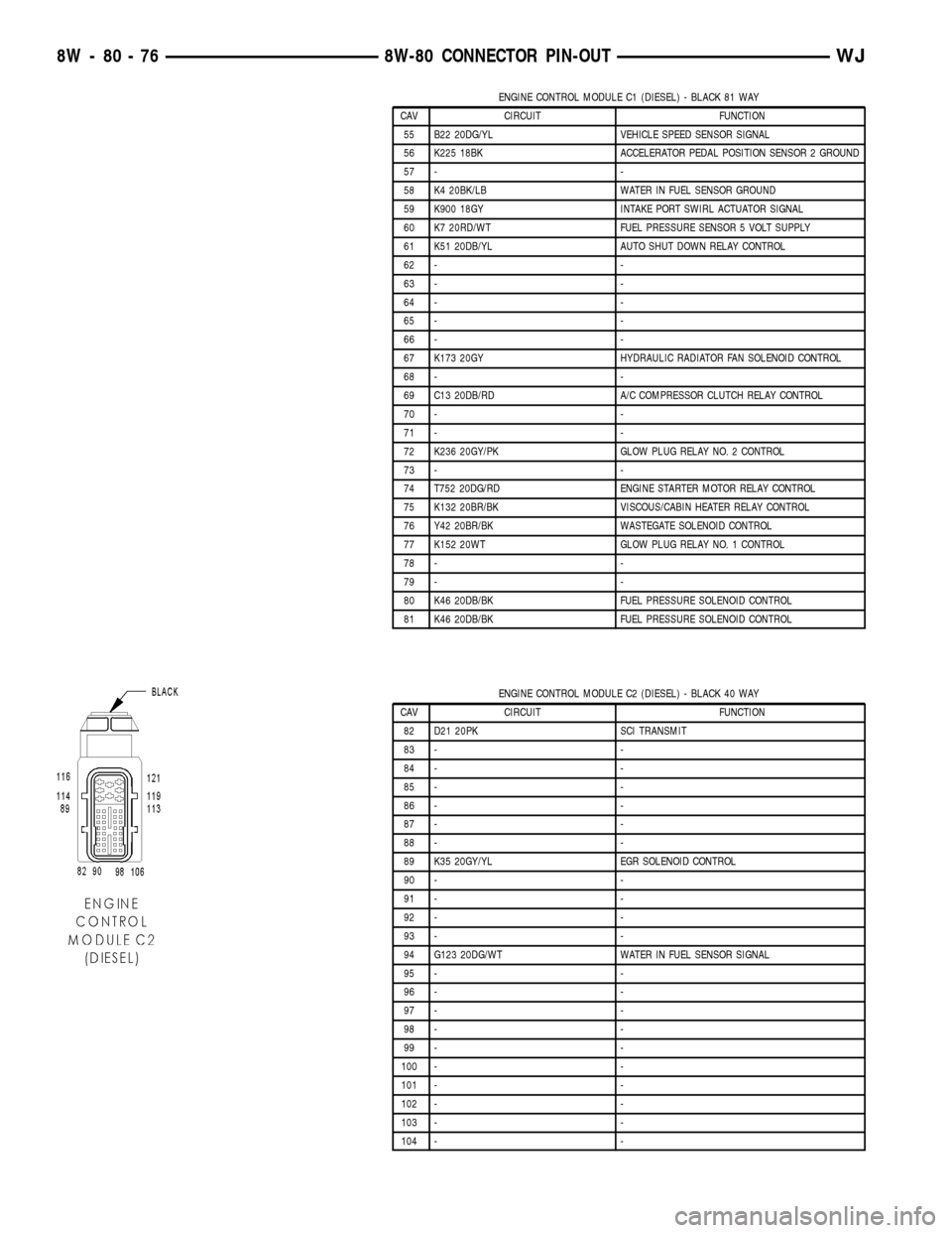
ENGINE CONTROL MODULE C1 (DIESEL) - BLACK 81 WAY
CAV CIRCUIT FUNCTION
55 B22 20DG/YL VEHICLE SPEED SENSOR SIGNAL
56 K225 18BK ACCELERATOR PEDAL POSITION SENSOR 2 GROUND
57 - -
58 K4 20BK/LB WATER IN FUEL SENSOR GROUND
59 K900 18GY INTAKE PORT SWIRL ACTUATOR SIGNAL
60 K7 20RD/WT FUEL PRESSURE SENSOR 5 VOLT SUPPLY
61 K51 20DB/YL AUTO SHUT DOWN RELAY CONTROL
62 - -
63 - -
64 - -
65 - -
66 - -
67 K173 20GY HYDRAULIC RADIATOR FAN SOLENOID CONTROL
68 - -
69 C13 20DB/RD A/C COMPRESSOR CLUTCH RELAY CONTROL
70 - -
71 - -
72 K236 20GY/PK GLOW PLUG RELAY NO. 2 CONTROL
73 - -
74 T752 20DG/RD ENGINE STARTER MOTOR RELAY CONTROL
75 K132 20BR/BK VISCOUS/CABIN HEATER RELAY CONTROL
76 Y42 20BR/BK WASTEGATE SOLENOID CONTROL
77 K152 20WT GLOW PLUG RELAY NO. 1 CONTROL
78 - -
79 - -
80 K46 20DB/BK FUEL PRESSURE SOLENOID CONTROL
81 K46 20DB/BK FUEL PRESSURE SOLENOID CONTROL
ENGINE CONTROL MODULE C2 (DIESEL) - BLACK 40 WAY
CAV CIRCUIT FUNCTION
82 D21 20PK SCI TRANSMIT
83 - -
84 - -
85 - -
86 - -
87 - -
88 - -
89 K35 20GY/YL EGR SOLENOID CONTROL
90 - -
91 - -
92 - -
93 - -
94 G123 20DG/WT WATER IN FUEL SENSOR SIGNAL
95 - -
96 - -
97 - -
98 - -
99 - -
100 - -
101 - -
102 - -
103 - -
104 - -
8W - 80 - 76 8W-80 CONNECTOR PIN-OUTWJ
Page 1156 of 2199

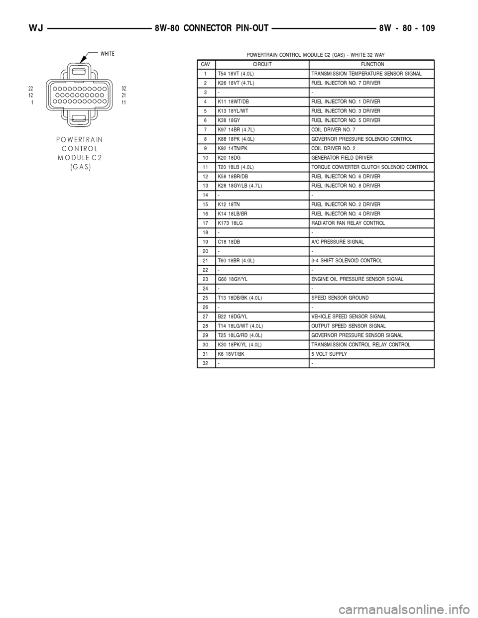
POWERTRAIN CONTROL MODULE C2 (GAS) - WHITE 32 WAY
CAV CIRCUIT FUNCTION
1 T54 18VT (4.0L) TRANSMISSION TEMPERATURE SENSOR SIGNAL
2 K26 18VT (4.7L) FUEL INJECTOR NO. 7 DRIVER
3- -
4 K11 18WT/DB FUEL INJECTOR NO. 1 DRIVER
5 K13 18YL/WT FUEL INJECTOR NO. 3 DRIVER
6 K38 18GY FUEL INJECTOR NO. 5 DRIVER
7 K97 14BR (4.7L) COIL DRIVER NO. 7
8 K88 18PK (4.0L) GOVERNOR PRESSURE SOLENOID CONTROL
9 K92 14TN/PK COIL DRIVER NO. 2
10 K20 18DG GENERATOR FIELD DRIVER
11 T20 18LB (4.0L) TORQUE CONVERTER CLUTCH SOLENOID CONTROL
12 K58 18BR/DB FUEL INJECTOR NO. 6 DRIVER
13 K28 18GY/LB (4.7L) FUEL INJECTOR NO. 8 DRIVER
14 - -
15 K12 18TN FUEL INJECTOR NO. 2 DRIVER
16 K14 18LB/BR FUEL INJECTOR NO. 4 DRIVER
17 K173 18LG RADIATOR FAN RELAY CONTROL
18 - -
19 C18 18DB A/C PRESSURE SIGNAL
20 - -
21 T60 18BR (4.0L) 3-4 SHIFT SOLENOID CONTROL
22 - -
23 G60 18GY/YL ENGINE OIL PRESSURE SENSOR SIGNAL
24 - -
25 T13 18DB/BK (4.0L) SPEED SENSOR GROUND
26 - -
27 B22 18DG/YL VEHICLE SPEED SENSOR SIGNAL
28 T14 18LG/WT (4.0L) OUTPUT SPEED SENSOR SIGNAL
29 T25 18LG/RD (4.0L) GOVERNOR PRESSURE SENSOR SIGNAL
30 K30 18PK/YL (4.0L) TRANSMISSION CONTROL RELAY CONTROL
31 K6 18VT/BK 5 VOLT SUPPLY
32 - -
WJ8W-80 CONNECTOR PIN-OUT 8W - 80 - 109
Page 1157 of 2199

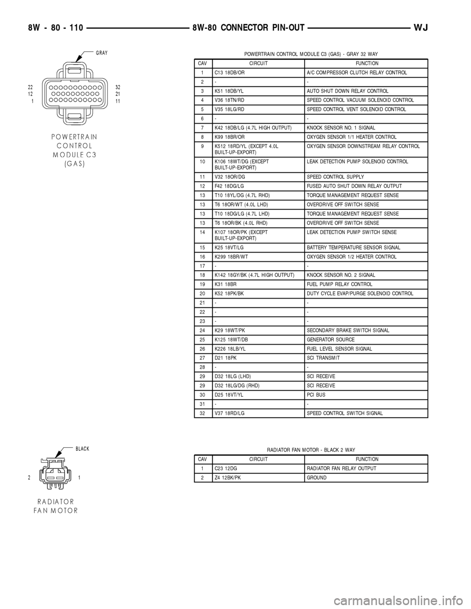
POWERTRAIN CONTROL MODULE C3 (GAS) - GRAY 32 WAY
CAV CIRCUIT FUNCTION
1 C13 18DB/OR A/C COMPRESSOR CLUTCH RELAY CONTROL
2- -
3 K51 18DB/YL AUTO SHUT DOWN RELAY CONTROL
4 V36 18TN/RD SPEED CONTROL VACUUM SOLENOID CONTROL
5 V35 18LG/RD SPEED CONTROL VENT SOLENOID CONTROL
6- -
7 K42 18DB/LG (4.7L HIGH OUTPUT) KNOCK SENSOR NO. 1 SIGNAL
8 K99 18BR/OR OXYGEN SENSOR 1/1 HEATER CONTROL
9 K512 18RD/YL (EXCEPT 4.0L
BUILT-UP-EXPORT)OXYGEN SENSOR DOWNSTREAM RELAY CONTROL
10 K106 18WT/DG (EXCEPT
BUILT-UP-EXPORT)LEAK DETECTION PUMP SOLENOID CONTROL
11 V32 18OR/DG SPEED CONTROL SUPPLY
12 F42 18DG/LG FUSED AUTO SHUT DOWN RELAY OUTPUT
13 T10 18YL/DG (4.7L RHD) TORQUE MANAGEMENT REQUEST SENSE
13 T6 18OR/WT (4.0L LHD) OVERDRIVE OFF SWITCH SENSE
13 T10 18DG/LG (4.7L LHD) TORQUE MANAGEMENT REQUEST SENSE
13 T6 18OR/BK (4.0L RHD) OVERDRIVE OFF SWITCH SENSE
14 K107 18OR/PK (EXCEPT
BUILT-UP-EXPORT)LEAK DETECTION PUMP SWITCH SENSE
15 K25 18VT/LG BATTERY TEMPERATURE SENSOR SIGNAL
16 K299 18BR/WT OXYGEN SENSOR 1/2 HEATER CONTROL
17 - -
18 K142 18GY/BK (4.7L HIGH OUTPUT) KNOCK SENSOR NO. 2 SIGNAL
19 K31 18BR FUEL PUMP RELAY CONTROL
20 K52 18PK/BK DUTY CYCLE EVAP/PURGE SOLENOID CONTROL
21 - -
22 - -
23 - -
24 K29 18WT/PK SECONDARY BRAKE SWITCH SIGNAL
25 K125 18WT/DB GENERATOR SOURCE
26 K226 18LB/YL FUEL LEVEL SENSOR SIGNAL
27 D21 18PK SCI TRANSMIT
28 - -
29 D32 18LG (LHD) SCI RECEIVE
29 D32 18LG/DG (RHD) SCI RECEIVE
30 D25 18VT/YL PCI BUS
31 - -
32 V37 18RD/LG SPEED CONTROL SWITCH SIGNAL
RADIATOR FAN MOTOR - BLACK 2 WAY
CAV CIRCUIT FUNCTION
1 C23 12DG RADIATOR FAN RELAY OUTPUT
2 Z4 12BK/PK GROUND
8W - 80 - 110 8W-80 CONNECTOR PIN-OUTWJ