2002 JEEP GRAND CHEROKEE 100
[x] Cancel search: 100Page 13 of 2199

INTERNATIONAL SYMBOLS
DESCRIPTION
DaimlerChrysler Corporation uses international
symbols to identify engine compartment lubricant
and fluid inspection and fill locations (Fig. 1).
PARTS & LUBRICANT
RECOMMENDATION
STANDARD PROCEDURE - PARTS &
LUBRICANT RECOMMENDATIONS
Lubricating grease is rated for quality and usage
by the NLGI. All approved products have the NLGI
symbol (Fig. 2) on the label. At the bottom NLGI
symbol is the usage and quality identification letters.
Wheel bearing lubricant is identified by the letter
ªGº. Chassis lubricant is identified by the latter ªLº.
The letter following the usage letter indicates the
quality of the lubricant. The following symbols indi-
cate the highest quality.
When service is required, DaimlerChrysler Corpo-
ration recommends that only Mopartbrand parts,
lubricants and chemicals be used. Mopar provides
the best engineered products for servicing
DaimlerChrysler Corporation vehicles.
FLUID TYPES
DESCRIPTION
DESCRIPTION - ENGINE COOLANT
ETHYLENE-GLYCOL MIXTURES
CAUTION: Richer antifreeze mixtures cannot be
measured with normal field equipment and can
cause problems associated with 100 percent ethyl-
ene-glycol.
The required ethylene-glycol (antifreeze) and water
mixture depends upon the climate and vehicle oper-
ating conditions. The recommended mixture of 50/50
ethylene-glycol and water will provide protection
against freezing to -37 deg. C (-35 deg. F). The anti-
freeze concentrationmust alwaysbe a minimum of
44 percent, year-round in all climates.If percentage
is lower than 44 percent, engine parts may be
eroded by cavitation, and cooling system com-
ponents may be severely damaged by corrosion.
Maximum protection against freezing is provided
with a 68 percent antifreeze concentration, which
prevents freezing down to -67.7 deg. C (-90 deg. F). A
higher percentage will freeze at a warmer tempera-
ture. Also, a higher percentage of antifreeze can
cause the engine to overheat because the specific
heat of antifreeze is lower than that of water.
Use of 100 percent ethylene-glycol will cause for-
mation of additive deposits in the system, as the cor-
rosion inhibitive additives in ethylene-glycol require
the presence of water to dissolve. The deposits act as
insulation, causing temperatures to rise to as high as
149 deg. C (300) deg. F). This temperature is hot
enough to melt plastic and soften solder. The
increased temperature can result in engine detona-
tion. In addition, 100 percent ethylene-glycol freezes
at 22 deg. C (-8 deg. F ).
PROPYLENE-GLYCOL MIXTURES
It's overall effective temperature range is smaller
than that of ethylene-glycol. The freeze point of 50/50
propylene-glycol and water is -32 deg. C (-26 deg. F).
5 deg. C higher than ethylene-glycol's freeze point.
The boiling point (protection against summer boil-
over) of propylene-glycol is 125 deg. C (257 deg. F )
at 96.5 kPa (14 psi), compared to 128 deg. C (263
deg. F) for ethylene-glycol. Use of propylene-glycol
can result in boil-over or freeze-up on a cooling sys-
tem designed for ethylene-glycol. Propylene glycol
also has poorer heat transfer characteristics than
ethylene glycol. This can increase cylinder head tem-
peratures under certain conditions.
Fig. 1 INTERNATIONAL SYMBOLS
Fig. 2 NLGI Symbol
1 - WHEEL BEARINGS
2 - CHASSIS LUBRICATION
3 - CHASSIS AND WHEEL BEARINGS
0 - 2 LUBRICATION & MAINTENANCEWJ
Page 14 of 2199

Propylene-glycol/ethylene-glycol Mixtures can
cause the destabilization of various corrosion inhibi-
tors, causing damage to the various cooling system
components. Also, once ethylene-glycol and propy-
lene-glycol based coolants are mixed in the vehicle,
conventional methods of determining freeze point will
not be accurate. Both the refractive index and spe-
cific gravity differ between ethylene glycol and propy-
lene glycol.
DESCRIPTION - ENGINE COOLANT
WARNING: ANTIFREEZE IS AN ETHYLENE GLYCOL
BASE COOLANT AND IS HARMFUL IF SWAL-
LOWED OR INHALED. IF SWALLOWED, DRINK
TWO GLASSES OF WATER AND INDUCE VOMIT-
ING. IF INHALED, MOVE TO FRESH AIR AREA.
SEEK MEDICAL ATTENTION IMMEDIATELY. DO NOT
STORE IN OPEN OR UNMARKED CONTAINERS.
WASH SKIN AND CLOTHING THOROUGHLY AFTER
COMING IN CONTACT WITH ETHYLENE GLYCOL.
KEEP OUT OF REACH OF CHILDREN. DISPOSE OF
GLYCOL BASE COOLANT PROPERLY, CONTACT
YOUR DEALER OR GOVERNMENT AGENCY FOR
LOCATION OF COLLECTION CENTER IN YOUR
AREA. DO NOT OPEN A COOLING SYSTEM WHEN
THE ENGINE IS AT OPERATING TEMPERATURE OR
HOT UNDER PRESSURE, PERSONAL INJURY CAN
RESULT. AVOID RADIATOR COOLING FAN WHEN
ENGINE COMPARTMENT RELATED SERVICE IS
PERFORMED, PERSONAL INJURY CAN RESULT.
CAUTION: Use of Propylene Glycol based coolants
is not recommended, as they provide less freeze
protection and less corrosion protection.
The cooling system is designed around the coolant.
The coolant must accept heat from engine metal, in
the cylinder head area near the exhaust valves and
engine block. Then coolant carries the heat to the
radiator where the tube/fin radiator can transfer the
heat to the air.
The use of aluminum cylinder blocks, cylinder
heads, and water pumps requires special corrosion
protection. MopartAntifreeze/Coolant, 5
Year/100,000 Mile Formula (MS-9769), or the equiva-
lent ethylene glycol base coolant with organic corro-
sion inhibitors (called HOAT, for Hybrid Organic
Additive Technology) is recommended. This coolant
offers the best engine cooling without corrosion when
mixed with 50% Ethylene Glycol and 50% distilled
water to obtain a freeze point of -37ÉC (-35ÉF). If it
loses color or becomes contaminated, drain, flush,
and replace with fresh properly mixed coolant solu-
tion.CAUTION: MoparTAntifreeze/Coolant, 5
Year/100,000 Mile Formula (MS-9769) may not be
mixed with any other type of antifreeze. Mixing of
coolants other than specified (non-HOAT or other
HOAT), may result in engine damage that may not
be covered under the new vehicle warranty, and
decreased corrosion protection.
COOLANT PERFORMANCE
The required ethylene-glycol (antifreeze) and water
mixture depends upon climate and vehicle operating
conditions. The coolant performance of various mix-
tures follows:
Pure Water-Water can absorb more heat than a
mixture of water and ethylene-glycol. This is for pur-
pose of heat transfer only. Water also freezes at a
higher temperature and allows corrosion.
100 percent Ethylene-Glycol-The corrosion
inhibiting additives in ethylene-glycol need the pres-
ence of water to dissolve. Without water, additives
form deposits in system. These act as insulation
causing temperature to rise to as high as 149ÉC
(300ÉF). This temperature is hot enough to melt plas-
tic and soften solder. The increased temperature can
result in engine detonation. In addition, 100 percent
ethylene-glycol freezes at -22ÉC (-8ÉF).
50/50 Ethylene-Glycol and Water-Is the recom-
mended mixture, it provides protection against freez-
ing to -37ÉC (-34ÉF). The antifreeze concentration
must alwaysbe a minimum of 44 percent, year-
round in all climates. If percentage is lower, engine
parts may be eroded by cavitation. Maximum protec-
tion against freezing is provided with a 68 percent
antifreeze concentration, which prevents freezing
down to -67.7ÉC (-90ÉF). A higher percentage will
freeze at a warmer temperature. Also, a higher per-
centage of antifreeze can cause the engine to over-
heat because specific heat of antifreeze is lower than
that of water.
CAUTION: Richer antifreeze mixtures cannot be
measured with normal field equipment and can
cause problems associated with 100 percent ethyl-
ene-glycol.
COOLANT SELECTION AND ADDITIVES
The use of aluminum cylinder blocks, cylinder
heads and water pumps requires special corrosion
protection. Only MopartAntifreeze/Coolant, 5
Year/100,000 Mile Formula (glycol base coolant with
corrosion inhibitors called HOAT, for Hybrid Organic
Additive Technology) is recommended. This coolant
offers the best engine cooling without corrosion when
mixed with 50% distilled water to obtain to obtain a
freeze point of -37ÉC (-35ÉF). If it loses color or
WJLUBRICATION & MAINTENANCE 0 - 3
FLUID TYPES (Continued)
Page 28 of 2199
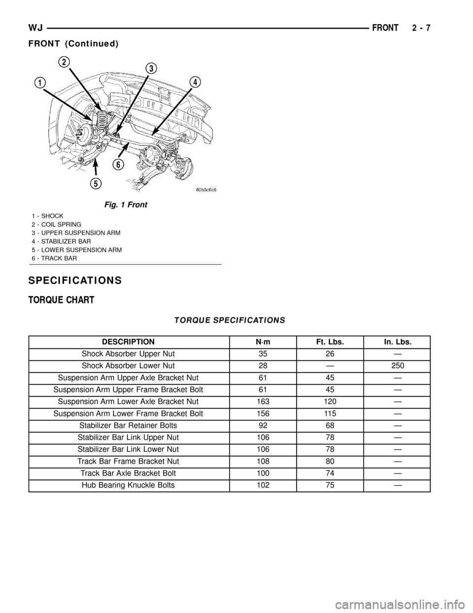
SPECIFICATIONS
TORQUE CHART
TORQUE SPECIFICATIONS
DESCRIPTION N´m Ft. Lbs. In. Lbs.
Shock Absorber Upper Nut 35 26 Ð
Shock Absorber Lower Nut 28 Ð 250
Suspension Arm Upper Axle Bracket Nut 61 45 Ð
Suspension Arm Upper Frame Bracket Bolt 61 45 Ð
Suspension Arm Lower Axle Bracket Nut 163 120 Ð
Suspension Arm Lower Frame Bracket Bolt 156 115 Ð
Stabilizer Bar Retainer Bolts 92 68 Ð
Stabilizer Bar Link Upper Nut 106 78 Ð
Stabilizer Bar Link Lower Nut 106 78 Ð
Track Bar Frame Bracket Nut 108 80 Ð
Track Bar Axle Bracket Bolt 100 74 Ð
Hub Bearing Knuckle Bolts 102 75 Ð
Fig. 1 Front
1 - SHOCK
2 - COIL SPRING
3 - UPPER SUSPENSION ARM
4 - STABILIZER BAR
5 - LOWER SUSPENSION ARM
6 - TRACK BAR
WJFRONT 2 - 7
FRONT (Continued)
Page 36 of 2199

(2) Install track bar to the frame rail bracket.
Install the bolt and nut finger tight.NOTE: It may be necessary to pry the axle assem-
bly over to install the track bar to the frame rail
bracket.
(3) Remove the supports and lower the vehicle.
(4) With the vehicle on the ground tighten the nut
at the frame rail bracket and to the bolt at the axle
bracket to 100 N´m (74 ft. lbs.).
(5) Check alignment specifications if a new track
bar was installed.
UPPER BALL JOINT
REMOVAL
Ball stud service procedures below require removal
of the hub bearing and axle shaft. Removal and
installation of upper and lower ball studs require the
use of Tool Kit 6289.
(1) Position tools as shown to remove and install
ball stud (Fig. 16).
Fig. 16 Upper
Fig. 15 Track Bar Axle Bracket
1 - AXLE BRACKET
2 - TRACK BAR
WJFRONT 2 - 15
TRACK BAR (Continued)
Page 39 of 2199

DIAGNOSIS AND TESTING - REAR
SUSPENSION
CONDITION POSSIBLE CAUSES CORRECTION
VEHICLE INSTABILITY 1. Loose or worn wheel bearings. 1. Replace wheel bearings.
2. Loose, worn or bent suspension
components.2. Inspect, tighten or replace components
as necessary.
3. Tire pressure. 3. Adjust tire pressure.
VEHICLE PULLS TO ONE
SIDE1. Weak or broken spring. 1. Replace spring.
2. Alignment. 2. Align vehicle to specifications.
3.Tires. 3. Replace tires.
4. Brakes. 4. Repair as necassary.
KNOCKING, RATTLING
OR SQUEAKING1. Worn shock bushings. 1. Replace shock.
2. Loose shock mounting. 2. Tighten to specifications.
3. Shock valve. 3. Replace shock.
4. Loose upper ball joint. 4. Replace ball joint.
5. Loose, worn or bent suspension
components.5. Inspect, tighten or replace components
as necessary.
IMPROPER TRACKING 1. Loose, worn or bent suspension
components.1. Inspect, tighten or replace components
as necessary.
2. Bent axle. 2.Replace axle.
SPECIFICATIONS
TORQUE CHART
TORQUE SPECIFICATIONS
DESCRIPTION N´m Ft. Lbs. In. Lbs.
Shock Absorber Upper Nut 108 80 Ð
Shock Absorber Lower Nut 115 85 Ð
Suspension Arm Upper Ball Joint Nut 142 105 Ð
Suspension Arm Upper Frame Bolts 100 74 Ð
Ball Joint Plate Bolts 136 100 Ð
Suspension Arms Lower Axle Bracket Nut 163 120 Ð
Suspension Arms Lower Frame Bracket Nut 156 115 Ð
Stabilizer Bar Retainer Bolts 54 40 Ð
Stabilizer Bar Bar Link Nut 54 40 Ð
Stabilizer Bar Bracket Link Nut 92 68 Ð
2 - 18 REARWJ
REAR (Continued)
Page 43 of 2199

INSTALLATION
(1) Install the ball joint on the differential hous-
ing.
(2) Install the ball joint mounting bolts and
tighten to 136 N´m (100 ft. lbs.).
(3) Raise the rear axle with a hydraulic jack to
align the upper arm with the ball joint.(4) Pull the arm down on the ball joint stud and
install anewnut. Tighten the nut to 142 N´m (105
ft. lbs.).
(5) Remove the supports and lower the vehicle.
UPPER CONTROL ARM
DESCRIPTION
The suspension arm uses vertical spool bushings to
isolate road noise. The suspension arm is bolted
through bushings to cage nuts in the body and a ball
joint plate to the top of the differential housing.
OPERATION
The upper suspension arm provides fore/aft and
lateral location of the rear axle. The suspension arm
travel is limited through the use of jounce bumpers
in compression and shock absorbers in rebound.
REMOVAL
(1) Raise and support the vehicle.
(2) Support the rear axle with a hydraulic jack.
(3) Remove the park brake cables and brake hose
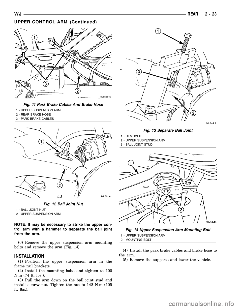
from the arm (Fig. 11).
(4) Remove the ball joint nut from the top of the
upper suspension arm (Fig. 12).
(5) Separate ball joint from the arm with Remover
8278 (Fig. 13).
Fig. 8 Ball Joint Nut
1 - BALL JOINT NUT
2 - UPPER SUSPENSION ARM
Fig. 9 Separate Ball Joint
1 - REMOVER
2 - UPPER SUSPENSION ARM
3 - BALL JOINT STUD
Fig. 10 Ball Joint Mounting Bolts
1 - BALL JOINT
2 - MOUNTING BOLTS
2 - 22 REARWJ
UPPER BALL JOINT (Continued)
Page 44 of 2199
NOTE: It may be necessary to strike the upper con-
trol arm with a hammer to separate the ball joint
from the arm.
(6) Remove the upper suspension arm mounting
bolts and remove the arm (Fig. 14).
INSTALLATION
(1) Position the upper suspension arm in the
frame rail brackets.
(2) Install the mounting bolts and tighten to 100
N´m (74 ft. lbs.).
(3) Pull the arm down on the ball joint stud and
install anewnut. Tighten the nut to 142 N´m (105
ft. lbs.).(4) Install the park brake cables and brake hose to
the arm.
(5) Remove the supports and lower the vehicle.
Fig. 11 Park Brake Cables And Brake Hose
1 - UPPER SUSPENSION ARM
2 - REAR BRAKE HOSE
3 - PARK BRAKE CABLES
Fig. 12 Ball Joint Nut
1 - BALL JOINT NUT
2 - UPPER SUSPENSION ARM
Fig. 13 Separate Ball Joint
1 - REMOVER
2 - UPPER SUSPENSION ARM
3 - BALL JOINT STUD
Fig. 14 Upper Suspension Arm Mounting Bolt
1 - UPPER SUSPENSION ARM
2 - MOUNTING BOLT
WJREAR 2 - 23
UPPER CONTROL ARM (Continued)
Page 59 of 2199

FRONT TUBE AXLE
TABLE OF CONTENTS
page page
FRONT TUBE AXLE
REMOVAL.............................14INSTALLATION.........................14
FRONT TUBE AXLE
REMOVAL
(1) Raise and support the vehicle.
(2) Position a lifting device under the axle and
secure axle to lift.
(3) Remove the wheels and tires.
(4) Remove the brake rotors (Refer to 5 - BRAKES/
HYDRAULIC/MECHANICAL/ROTORS - REMOVAL)
and calipers.
(5) Disconnect wheel sensor wiring harness from
the vehicle wiring harness.
(6) Remove stabilizer bar links at the axle.
(7) Remove shock absorbers from axle brackets.
(8) Removet track bar.
(9) Remove tie rod and drag link from the steering
knuckle.
(10) Remove steering damper from the axle
bracket.
(11) Remove upper and lower suspension arms
from the axle brackets.
(12) Lower the lift enough to remove the axle. The
coil springs will drop with the axle.
(13) Remove the coil springs from the axle.
INSTALLATION
CAUTION: The weight of the vehicle must be sup-
ported by the springs before suspension arms and
track bar fasteners are tightened. If not at their nor-mal ride position, ride height and handling could be
affected.
(1) Install springs and retainer clips and tighten
retainer bolts to 21 N´m (16 ft. lbs.).
(2) Lift and position axle under the vehicle and
align it with the spring pads.
(3) Position upper and lower suspension arms in
the axle brackets and loosely install bolts and nuts.
(4) Install track bar to the axle bracket and loosely
install bolt.
(5) Install shock absorbers and tighten bolts to 23
N´m (17 ft. lbs.).
(6) Install stabilizer bar links to the axle brackets
and tighten nuts to 95 N´m (70 ft. lbs.).
(7) Install drag link and tie rod to the steering
knuckles.
(8) Install steering damper to the axle bracket and
tighten nut to 75 N´m (55 ft. lbs.).
(9) Install the brake rotors and calipers.
(10) Connect wheel speed sensor wiring harness, if
equipped.
(11) Install the wheel and tire assemblies.
(12) Remove lift from the axle and lower the vehi-
cle.
(13) Tighten upper suspension arm nuts to 75 N´m
(55 ft. lbs.). Tighten lower suspension arm nuts to
115 N´m (85 ft. lbs.).
(14) Tighten track bar bolt at the axle bracket to
100 N´m (74 ft. lbs.).
(15) Check the front wheel alignment.
3 - 14 FRONT TUBE AXLEWJ