2002 JEEP GRAND CHEROKEE 100
[x] Cancel search: 100Page 61 of 2199

VARI-LOKTDIFFERENTIAL
In a standard differential if one wheel spins, the
opposite wheel will generate only as much torque as
the spinning wheel.
A gerotor pump and clutch pack are used to pro-
vide the torque transfer capability. One axle shaft is
splined to the gerotor pump and one of the differen-
tial side gears, which provides the input to the pump.
As a wheel begins to lose traction, the speed differ-
ential is transmitted from one side of the differential
to the other through the side gears. The motion of
one side gear relative to the other turns the inner
rotor of the pump. Since the outer rotor of the pump
is grounded to the differential case, the inner and
outer rotors are now moving relative to each other
and therefore creates pressure in the pump. The tun-ing of the front and rear axle orifices and valves
inside the gerotor pump is unique and each system
includes a torque-limiting pressure relief valve to
protect the clutch pack, which also facilitates vehicle
control under extreme side-to-side traction varia-
tions. The resulting pressure is applied to the clutch
pack and the transfer of torque is completed.
Under conditions in which opposite wheels are on
surfaces with widely different friction characteristics,
Vari-loktdelivers far more torque to the wheel on
the higher traction surface than do conventional
Trac-loktsystems. Because conventional Trac-lokt
differentials are initially pre-loaded to assure torque
transfer, normal driving (where inner and outer
wheel speeds differ during cornering, etc.) produces
torque transfer during even slight side-to-side speed
variations. Since these devices rely on friction from
this preload to transfer torque, normal use tends to
cause wear that reduces the ability of the differential
to transfer torque over time. By design, the Vari-lokt
system is less subject to wear, remaining more con-
sistent over time in its ability to transfer torque. The
coupling assembly is serviced as a unit. From a ser-
vice standpoint the coupling also benefits from using
the same lubricant supply as the ring and pinion
gears.
DIAGNOSIS AND TESTING
GEAR NOISE
Axle gear noise can be caused by insufficient lubri-
cant, incorrect backlash, tooth contact, worn/damaged
gears or the carrier housing not having the proper
offset and squareness.
Gear noise usually happens at a specific speed
range. The noise can also occur during a specific type
of driving condition. These conditions are accelera-
tion, deceleration, coast or constant load.
When road testing, first warm-up the axle fluid by
driving the vehicle at least 5 miles and then acceler-
ate the vehicle to the speed range where the noise is
the greatest. Shift out-of-gear and coast through the
peak-noise range. If the noise stops or changes
greatly:
²Check for insufficient lubricant.
²Incorrect ring gear backlash.
²Gear damage.
Differential side gears and pinions can be checked
by turning the vehicle. They usually do not cause
noise during straight-ahead driving when the gears
are unloaded. The side gears are loaded during vehi-
cle turns. A worn pinion mate shaft can also cause a
snapping or a knocking noise.
Fig. 1 DIFFERENTIAL-STRAIGHT AHEAD DRIVING
1 - IN STRAIGHT AHEAD DRIVING EACH WHEEL ROTATES AT
100% OF CASE SPEED
2 - PINION GEAR
3 - SIDE GEAR
4 - PINION GEARS ROTATE WITH CASE
Fig. 2 DIFFERENTIAL-ON TURNS
1 - PINION GEARS ROTATE ON PINION SHAFT
3 - 16 FRONT AXLE - 186FBIWJ
FRONT AXLE - 186FBI (Continued)
Page 66 of 2199

INSTALLATION
CAUTION: The weight of the vehicle must be sup-
ported by the springs before suspension arms and
track bar fasteners can be tightened. If springs are
not at their normal ride position, ride height and
handling could be affected.
(1) Install the springs and retainer clips. Tighten
the retainer bolts to 21 N´m (16 ft. lbs.).
(2) Support the axle on a lifting device and posi-
tion axle under the vehicle.
(3) Raise the axle and align it with the spring
pads.
(4) Position the upper and lower suspension arms
in the axle brackets. Loosely install bolts and nuts to
hold suspension arms to the axle brackets.
(5) Install vent hose to the axle shaft tube.
(6) Install track bar in the axle bracket and install
the bolt loosely.
(7) Install shock absorbers and tighten the bolts to
23 N´m (17 ft. lbs.).
(8) Install stabilizer bar links to the axle brackets
and tighten the nuts to 95 N´m (70 ft. lbs.).
(9) Install drag link and tie rod to the steering
knuckles.
(10) Install steering damper to the axle bracket
and tighten the nut to 75 N´m (55 ft. lbs.).
(11) Install the brake rotors (Refer to 5 - BRAKES/
HYDRAULIC/MECHANICAL/ROTORS - INSTALLA-
TION) and calipers.
(12) Connect the wheel speed sensor wiring har-
ness to the vehicle wiring harness.
(13) Align the previously made marks on the pro-
peller shaft and the yoke/pinion flange.
(14) Install propeller shaft to pinion flange bolts ,
if equipped.
(15) Install propeller shaft to yoke straps and
bolts, if equipped.
(16) Check and fill axle lubricant.
(17) Install the wheel and tire assemblies.
(18) Remove the lifting device from the axle and
lower the vehicle.
(19) Tighten the upper suspension arm nuts to 75
N´m (55 ft. lbs.). Tighten the lower suspension arm
nuts to 115 N´m (85 ft. lbs.).
(20) Tighten the track bar bolt at the axle bracket
to 100 N´m (74 ft. lbs.).
(21) Check the front wheel alignment.
ADJUSTMENTS
Ring and pinion gears are supplied as matched
sets only. The identifying numbers for the ring and
pinion gear are etched onto each gear (Fig. 3). A plus
(+) number, minus (±) number or zero (0) is etched
into the face of the pinion gear. This number is theamount (in thousandths of an inch) the depth varies
from the standard depth setting of a pinion etched
with a (0). The standard setting from the center line
of the ring gear to the back face of the pinion is 92.1
mm (3.625 in.). The standard depth provides the best
gear tooth contact pattern. Refer to Backlash and
Contact Pattern Analysis paragraph in this section
for additional information.
Compensation for pinion depth variance is
achieved with a select shim/oil slinger. The shims are
placed between the rear pinion bearing and the pin-
ion gear head (Fig. 4).
Fig. 3 PINION GEAR ID NUMBERS
1 - PRODUCTION NUMBERS
2 - DRIVE PINION GEAR DEPTH VARIANCE
3 - GEAR MATCHING NUMBER
Fig. 4 ADJUSTMENT SHIM LOCATIONS
1 - PINION DEPTH SHIM/OIL SLINGER
2 - DIFFERENTIAL BEARING SHIM
3 - RING GEAR
4 - DIFFERENTIAL BEARING SHIM
5 - COLLAPSIBLE SPACER
WJFRONT AXLE - 186FBI 3 - 21
FRONT AXLE - 186FBI (Continued)
Page 101 of 2199

(13) Separate rear axle ball joint from the upper
suspension arm with Remover 8278 (Fig. 4).
(14) Disconnect shock absorbers from axle.
(15) Disconnect track bar.
(16) Disconnect lower suspension arms from the
axle brackets.
(17) Separate the axle from the vehicle.
INSTALLATION
CAUTION: The weight of the vehicle must be sup-
ported by the springs before suspension arms and
track bar fasteners are tightened. If springs are not
at their normal ride position, vehicle ride height and
handling could be affected.
(1) Raise axle with lift and align coil springs.
(2) Install lower suspension arms in axle brackets.
Install nuts and bolts, do not tighten bolts at this
time.
(3) Install upper suspension arm on rear axle ball
joint.
(4) Install rear axle ball joint nut and tighten to
122 N´m (90 ft.lbs.) (Fig. 5).
(5) Install track bar and attachment bolts, do not
tighten bolts at this time.
(6) Install shock absorbers and tighten nuts to 60
N´m (44 ft. lbs.).(7) Install stabilizer bar links and tighten nuts to
36 N´m (27 ft. lbs.).
(8) Install wheel speed sensors.
(9) Connect parking brake cable to brackets and
lever.
(10) Install brake rotors and calipers.
(11) Install the brake hose to the axle junction
block.
(12) Install axle vent hose.
(13) Align propeller shaft and pinion yoke refer-
ence marks. Install U-joint straps and nuts tighten to
19 N´m (14 ft. lbs.).
(14) Install the wheels and tires.
(15) Add gear lubricant, if necessary.
(16) Remove support and lower the vehicle.
(17) Tighten lower suspension arm bolts to 177
N´m (130 ft. lbs.).
(18) Tighten track bar bolts to 100 N´m (74 ft.
lbs.).
ADJUSTMENTS
Ring and pinion gears are supplied as matched
sets only. The identifying numbers for the ring and
pinion gear are etched into the face of each gear (Fig.
6). A plus (+) number, minus (±) number or zero (0) is
etched into the face of the pinion gear. This number
is the amount (in thousandths of an inch) the depth
varies from the standard depth setting of a pinion
etched with a (0). The standard setting from the cen-
ter line of the ring gear to the back face of the pinion
is 96.850 mm (3.813 in.). The standard depth pro-
vides the best gear tooth contact pattern. Refer to
Backlash and Contact Pattern Analysis paragraph in
this section for additional information.
Fig. 4 REAR BALL JOINT
1 - REMOVER
2 - UPPER SUSPENSION ARM
3 - BALL JOINT STUD
Fig. 5 REAR BALL JOINT NUT
1 - UPPER SUSPENSION ARM
2 - REAR AXLE BALL JOINT
3 - REAR AXLE
3 - 56 REAR AXLE - 198RBIWJ
REAR AXLE - 198RBI (Continued)
Page 134 of 2199

(15) Invert the differential case in the vise.
(16) Installnewring gear bolts and alternately
tighten to 136 N´m (100 ft. lbs.) (Fig. 88).
CAUTION: Never reuse the ring gear bolts. The
bolts can fracture causing extensive damage.
(17) Install differential in housing and verify dif-
ferential bearing preload, gear mesh and contact pat-
tern. Refer to Ajustments for procedure.
CAUTION: When installing a Vari-lokTdifferential
(Fig. 89), the oil feed tube must point to the bottom
of the housing. If differential is installed with the oil
feed tube pointed toward the top, the anti-rotation
tabs will be damaged.
(18) Install differential cover and fill with gear
lubricant.
(19) Install the propeller shaft with the reference
marks aligned.
(20) Remove supports and lower vehicle.
Fig. 87 PINION ROTATING TORQUE
1 - PINION YOKE/COMPANION FLANGE
2 - INCH POUND TORQUE WRENCH
Fig. 88 RING GEAR
1 - TORQUE WRENCH
2 - RING GEAR BOLT
3 - RING GEAR
4 - CASE
Fig. 89 VARI-LOK
1 - ANTI-ROTATION TAB
2 - OIL FEED TUBE
WJREAR AXLE - 198RBI 3 - 89
PINION GEAR/RING GEAR (Continued)
Page 136 of 2199

TRAC-LOKTDIFFERENTIAL
The differential clutches are engaged by two con-
current forces. The first being the preload force
exerted through Belleville spring washers within the
clutch packs. The second is the separating forces gen-
erated by the side gears as torque is applied through
the ring gear (Fig. 3).
This design provides the differential action needed
for turning corners and for driving straight ahead
during periods of unequal traction. When one wheel
looses traction, the clutch packs transfer additional
torque to the wheel having the most traction. The
differential resist wheel spin on bumpy roads and
provide more pulling power when one wheel looses
traction. Pulling power is provided continuously until
both wheels loose traction. If both wheels slip due tounequal traction, the operation is normal. In extreme
cases of differences of traction, the wheel with the
least traction may spin.VARI-LOKTDIFFERENTIAL
In a standard differential, if one wheel spins, the
opposite wheel will generate only as much torque as
the spinning wheel.
A gerotor pump and clutch pack are used to pro-
vide the torque transfer capability. One axle shaft is
splined to the gerotor pump and one of the differen-
tial side gears, which provides the input to the pump.
As a wheel begins to lose traction, the speed differ-
ential is transmitted from one side of the differential
to the other through the side gears. The motion of
one side gear relative to the other turns the inner
rotor of the pump. Since the outer rotor of the pump
is grounded to the differential case, the inner and
outer rotors are now moving relative to each other
Fig. 1 OPERATION-STRAIGHT AHEAD DRIVING
1 - IN STRAIGHT AHEAD DRIVING EACH WHEEL ROTATES AT
100% OF CASE SPEED
2 - PINION GEAR
3 - SIDE GEAR
4 - PINION GEARS ROTATE WITH CASE
Fig. 2 OPERATION-ON TURNS
1 - PINION GEARS ROTATE ON PINION SHAFT
Fig. 3 TRAC-LOK LIMITED SLIP DIFFERENTIAL
1 - CASE
2 - RING GEAR
3 - DRIVE PINION
4 - PINION GEAR
5 - MATE SHAFT
6 - CLUTCH PACK
7 - SIDE GEAR
8 - CLUTCH PACK
WJREAR AXLE - 226RBA 3 - 91
REAR AXLE - 226RBA (Continued)
Page 141 of 2199
(3) Remove the wheels and tires.
(4) Remove brake calipers and rotors.
(5) Disconnect parking brake cables from brackets
and lever.
(6) Remove wheel speed sensors.
(7) Remove brake hose at the axle junction block.
Do not disconnect the brake hydraulic lines at the
calipers.
(8) Disconnect the vent hose from the axle shaft
tube.
(9) Mark propeller shaft and yokes for installation
reference.
(10) Remove propeller shaft.
(11) Disconnect stabilizer bar links.
(12) Remove upper suspension arm rear axle ball
joint nut.
(13) Separate rear axle ball joint from the upper
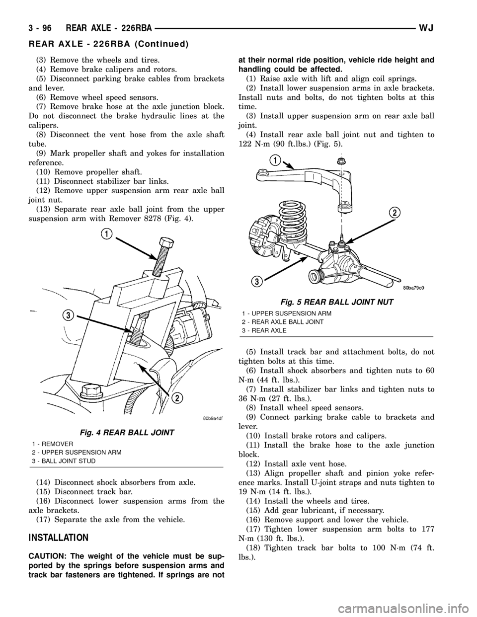
suspension arm with Remover 8278 (Fig. 4).
(14) Disconnect shock absorbers from axle.
(15) Disconnect track bar.
(16) Disconnect lower suspension arms from the
axle brackets.
(17) Separate the axle from the vehicle.
INSTALLATION
CAUTION: The weight of the vehicle must be sup-
ported by the springs before suspension arms and
track bar fasteners are tightened. If springs are notat their normal ride position, vehicle ride height and
handling could be affected.
(1) Raise axle with lift and align coil springs.
(2) Install lower suspension arms in axle brackets.
Install nuts and bolts, do not tighten bolts at this
time.
(3) Install upper suspension arm on rear axle ball
joint.
(4) Install rear axle ball joint nut and tighten to
122 N´m (90 ft.lbs.) (Fig. 5).
(5) Install track bar and attachment bolts, do not
tighten bolts at this time.
(6) Install shock absorbers and tighten nuts to 60
N´m (44 ft. lbs.).
(7) Install stabilizer bar links and tighten nuts to
36 N´m (27 ft. lbs.).
(8) Install wheel speed sensors.
(9) Connect parking brake cable to brackets and
lever.
(10) Install brake rotors and calipers.
(11) Install the brake hose to the axle junction
block.
(12) Install axle vent hose.
(13) Align propeller shaft and pinion yoke refer-
ence marks. Install U-joint straps and nuts tighten to
19 N´m (14 ft. lbs.).
(14) Install the wheels and tires.
(15) Add gear lubricant, if necessary.
(16) Remove support and lower the vehicle.
(17) Tighten lower suspension arm bolts to 177
N´m (130 ft. lbs.).
(18) Tighten track bar bolts to 100 N´m (74 ft.
lbs.).
Fig. 4 REAR BALL JOINT
1 - REMOVER
2 - UPPER SUSPENSION ARM
3 - BALL JOINT STUD
Fig. 5 REAR BALL JOINT NUT
1 - UPPER SUSPENSION ARM
2 - REAR AXLE BALL JOINT
3 - REAR AXLE
3 - 96 REAR AXLE - 226RBAWJ
REAR AXLE - 226RBA (Continued)
Page 145 of 2199
(2) Install ring gear on differential case and
tighten bolts to specification.
(3)
Install Dummy Bearings 6929-A on differential case.
(4) Install differential case in the housing.
(5) Record the thickness of Dummy Shims 8107,
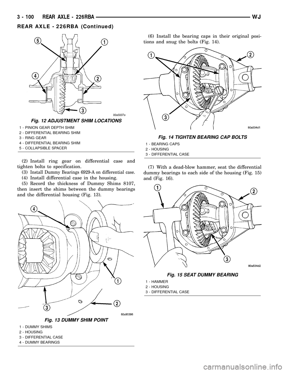
then insert the shims between the dummy bearings
and the differential housing (Fig. 13).(6) Install the bearing caps in their original posi-
tions and snug the bolts (Fig. 14).
(7) With a dead-blow hammer, seat the differential
dummy bearings to each side of the housing (Fig. 15)
and (Fig. 16).
Fig. 12 ADJUSTMENT SHIM LOCATIONS
1 - PINION GEAR DEPTH SHIM
2 - DIFFERENTIAL BEARING SHIM
3 - RING GEAR
4 - DIFFERENTIAL BEARING SHIM
5 - COLLAPSIBLE SPACER
Fig. 13 DUMMY SHIM POINT
1 - DUMMY SHIMS
2 - HOUSING
3 - DIFFERENTIAL CASE
4 - DUMMY BEARINGS
Fig. 14 TIGHTEN BEARING CAP BOLTS
1 - BEARING CAPS
2 - HOUSING
3 - DIFFERENTIAL CASE
Fig. 15 SEAT DUMMY BEARING
1 - HAMMER
2 - HOUSING
3 - DIFFERENTIAL CASE
3 - 100 REAR AXLE - 226RBAWJ
REAR AXLE - 226RBA (Continued)
Page 150 of 2199
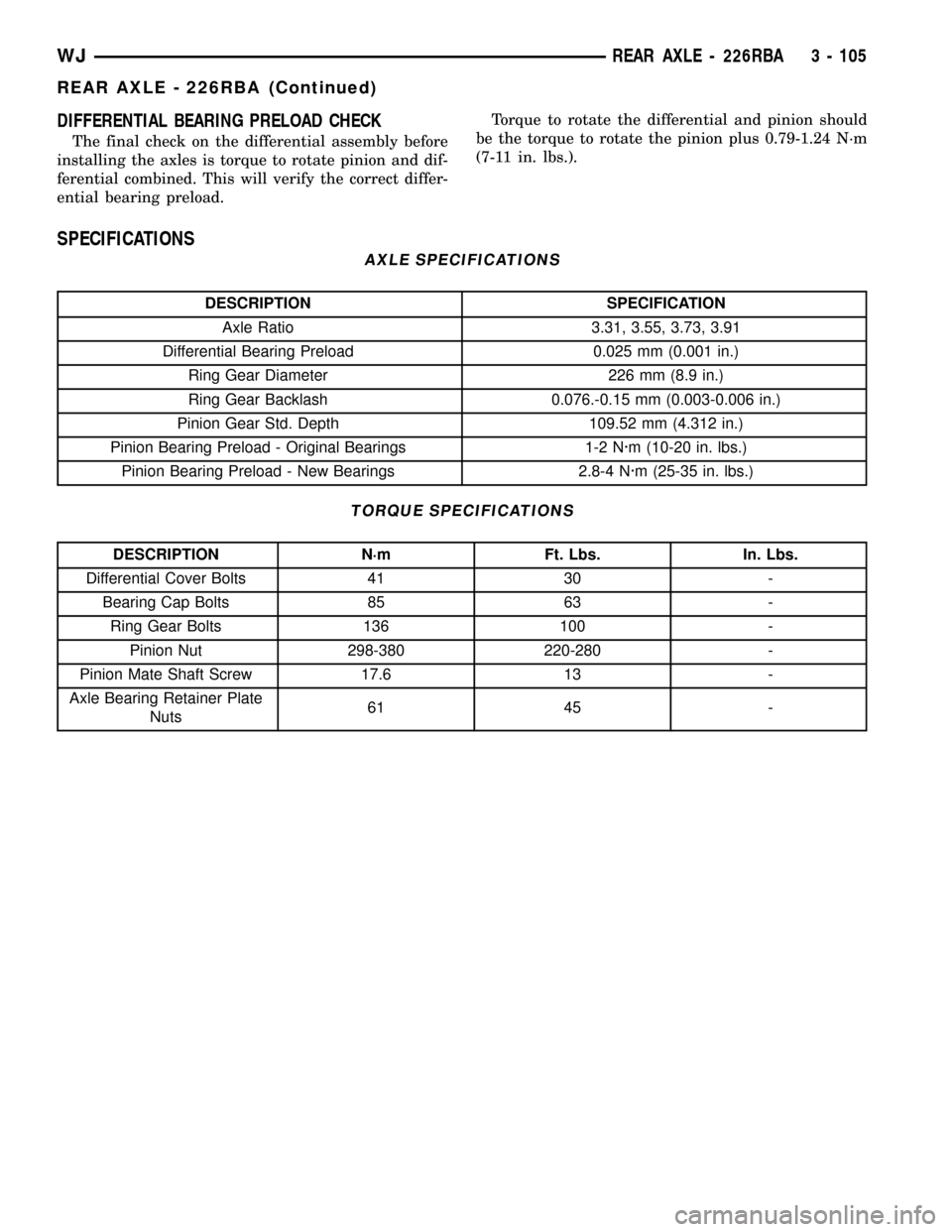
DIFFERENTIAL BEARING PRELOAD CHECK
The final check on the differential assembly before
installing the axles is torque to rotate pinion and dif-
ferential combined. This will verify the correct differ-
ential bearing preload.Torque to rotate the differential and pinion should
be the torque to rotate the pinion plus 0.79-1.24 N´m
(7-11 in. lbs.).
SPECIFICATIONS
AXLE SPECIFICATIONS
DESCRIPTION SPECIFICATION
Axle Ratio 3.31, 3.55, 3.73, 3.91
Differential Bearing Preload 0.025 mm (0.001 in.)
Ring Gear Diameter 226 mm (8.9 in.)
Ring Gear Backlash 0.076.-0.15 mm (0.003-0.006 in.)
Pinion Gear Std. Depth 109.52 mm (4.312 in.)
Pinion Bearing Preload - Original Bearings 1-2 N´m (10-20 in. lbs.)
Pinion Bearing Preload - New Bearings 2.8-4 N´m (25-35 in. lbs.)
TORQUE SPECIFICATIONS
DESCRIPTION N´m Ft. Lbs. In. Lbs.
Differential Cover Bolts 41 30 -
Bearing Cap Bolts 85 63 -
Ring Gear Bolts 136 100 -
Pinion Nut 298-380 220-280 -
Pinion Mate Shaft Screw 17.6 13 -
Axle Bearing Retainer Plate
Nuts61 45 -
WJREAR AXLE - 226RBA 3 - 105
REAR AXLE - 226RBA (Continued)