2002 JEEP GRAND CHEROKEE Car seat
[x] Cancel search: Car seatPage 1844 of 2199
INPUT AND LOW RANGE GEARS
Inspect the low range gear pinions and pinion pins.
Replace the low range gear if any of the pins or pin-
ions are worn or damaged.
Inspect the thrust washers, retainer, and snap-
ring. Replace the snap-ring if bent, or distorted.
Replace the thrust washers and retainer if worn,
cracked or damaged in any way.
Examine the input gear carefully. Be sure the gear
teeth and bearing surfaces are in good condition.
Replace the gear if wear or damage is evident.
Check the input gear pilot bearing. Rotate the
bearing and check for roughness or noise. Also check
bearing position in the bore. The bearing should be
recessed approximately 2.5 mm (0.100 in.) below the
top edge of the bore. The bearing should not be
seated at the bottom of the bore. Replace the bearing
if worn, or roughness is evident. Replace both the
gear and bearing if the bearing is a loose fit in the
bore.
GEAR CASE AND RETAINERS
Examine both case halves and retainers carefully.
Replace any retainer or case half if wear, cracks, or
other damage is evident.
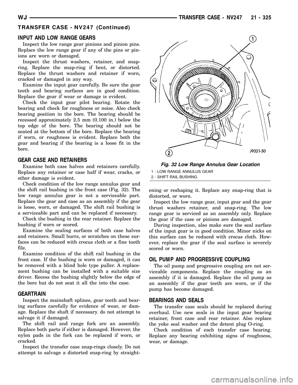
Check condition of the low range annulus gear and
the shift rail bushing in the front case (Fig. 32). The
low range annulus gear is not a serviceable part.
Replace the gear and case as an assembly if the gear
is loose, worn, or damaged. The shift rail bushing is
a serviceable part and can be replaced if necessary.
Check the bushing in the rear retainer. Replace the
bushing if worn or scored.
Examine the sealing surfaces of both case halves
and retainers. Small burrs, or scratches on these sur-
faces can be reduced with crocus cloth or a fine tooth
file.
Examine condition of the shift rail bushing in the
front case. If the bushing is worn or damaged, it can
be removed with a blind hole type puller. A replace-
ment bushing can be installed with a suitable size
driver. Recess the bushing slightly below the edge of
the bore but do not seat it all the into the case.
GEARTRAIN
Inspect the mainshaft splines, gear teeth and bear-
ing surfaces carefully for evidence of wear, or dam-
age. Replace the shaft if necessary. do not attempt to
salvage it if damaged.
The shift rail and range fork are an assembly.
Replace both parts if either is damaged. However, the
nylon pads in the fork can be replaced if worn, or
cracked.
Inspect the transfer case snap-rings closely. Do not
attempt to salvage a distorted snap-ring by straight-ening or reshaping it. Replace any snap-ring that is
distorted, or worn.
Inspect the low range gear, input gear and the gear
thrust washers retainer, and snap-ring. The low
range gear is serviced as an assembly only. Replace
the gear if the case or pinions are damaged.
During inspection, also make sure the seal surface
of the input gear is in good condition. Minor nicks on
this surface can be reduced with crocus cloth. How-
ever, replace the gear if the seal surface is severely
scored or worn.
OIL PUMP AND PROGRESSIVE COUPLING
The oil pump and progressive coupling are not ser-
viceable components. Replace the coupling as an
assembly if it is damaged. Replace the oil pump as
an assembly if the gear teeth are worn, or if the
pump has become damaged.
BEARINGS AND SEALS
The transfer case seals should be replaced during
overhaul. Use new seals in the input gear bearing
retainer, front case and rear retainer. Also replace
the yoke seal washer and the detent plug O-ring.
Check condition of each transfer case bearing.
Replace any bearing exhibiting signs of roughness,
wear, or damage.
Fig. 32 Low Range Annulus Gear Location
1 - LOW RANGE ANNULUS GEAR
2 - SHIFT RAIL BUSHING
WJTRANSFER CASE - NV247 21 - 325
TRANSFER CASE - NV247 (Continued)
Page 1870 of 2199
²Bent or dented
²Leak air through welds
²Have damaged bolt holes
Wheel repairs employing hammering, heating, or
welding are not allowed.
Original equipment wheels are available through
your dealer. Replacement wheels from any other
source should be equivalent in:
²Load carrying capacity
²Diameter
²Width²Offset
²Mounting configuration
Failure to use equivalent replacement wheels may
affect the safety and handling of your vehicle.
Replacement withusedwheels is not recommended.
Their service history may have included severe treat-
ment.
SPECIFICATIONS
TORQUE CHART
TORQUE SPECIFICATIONS
DESCRIPTION N´m Ft. Lbs. In. Lbs.
Lug Nut
1/2 X 20 with 60É Cone115-150 85-115 Ð
STUDS
REMOVAL
CAUTION: Do not use a hammer to remove wheel
studs.
(1) Raise and support vehicle.
(2) Remove wheel and tire assembly.
(3) Remove brake caliper, caliper adapter and
rotor,(Refer to 5 - BRAKES/HYDRAULIC/MECHAN-
ICAL/ROTORS - REMOVAL).
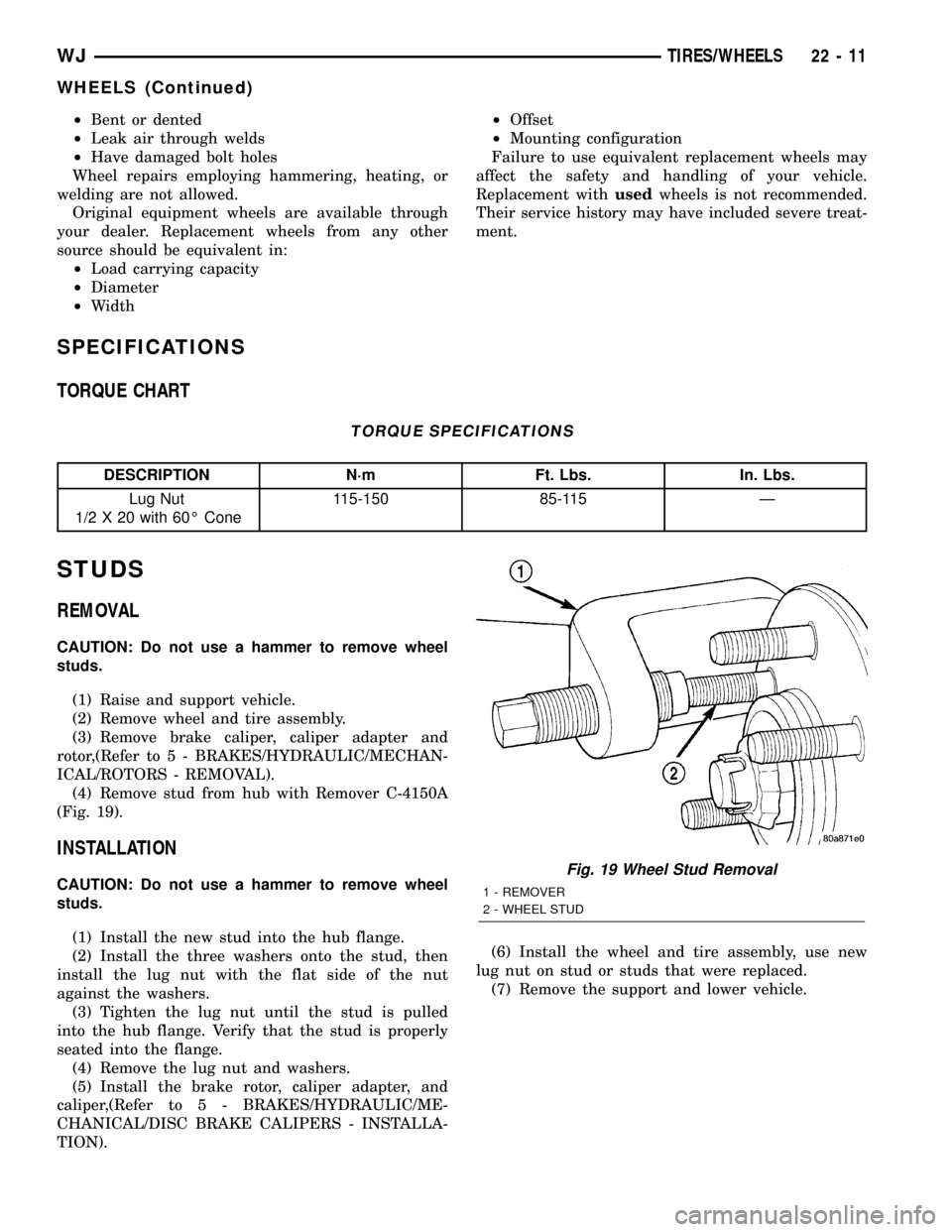
(4) Remove stud from hub with Remover C-4150A
(Fig. 19).
INSTALLATION
CAUTION: Do not use a hammer to remove wheel
studs.
(1) Install the new stud into the hub flange.
(2) Install the three washers onto the stud, then
install the lug nut with the flat side of the nut
against the washers.
(3) Tighten the lug nut until the stud is pulled
into the hub flange. Verify that the stud is properly
seated into the flange.
(4) Remove the lug nut and washers.
(5) Install the brake rotor, caliper adapter, and
caliper,(Refer to 5 - BRAKES/HYDRAULIC/ME-
CHANICAL/DISC BRAKE CALIPERS - INSTALLA-
TION).(6) Install the wheel and tire assembly, use new
lug nut on stud or studs that were replaced.
(7) Remove the support and lower vehicle.Fig. 19 Wheel Stud Removal
1 - REMOVER
2 - WHEEL STUD
WJTIRES/WHEELS 22 - 11
WHEELS (Continued)
Page 1944 of 2199
(4) Install screw attaching B-pillar lower trim to
B-pillar.
(5) Install screw attaching front of B-pillar lower
trim to floor.
(6) Install screw attaching front of quarter panel
trim to floor.
(7) Install front seat shoulder belt anchor bolt.
(8) Install front seat shoulder belt height adjust-
ment knob and turning loop.
(9) Install front door sill trim (Refer to 23 - BODY/
INTERIOR/DOOR SILL TRIM - INSTALLATION).
B-PILLAR UPPER TRIM
REMOVAL
(1) Remove shoulder belt height adjustment knob.
(2) Remove front seat belt turning loop.
(3) Remove the screw attaching lower B pillar
trim.
(4) Pull lower B pillar trim out far enough to
remove upper trim panel.
(5) Grasp upper B-pillar trim and pull outward to
detach from B-pillar (Fig. 2).
INSTALLATION
(1) Position trim panel on B-pillar (Fig. 2).
(2) Ensure trim panel covers inner edge of door
opening weatherstrip and press inward to seat.
(3) Install screw attaching lower B pillar trim
panel.
(4) Install front seat belt turning loop.
(5) Install shoulder belt height adjustment knob.
CARPETS AND FLOOR MATS
REMOVAL
REMOVAL - FRONT CARPET
(1) Remove door sill trim (Refer to 23 - BODY/IN-
TERIOR/DOOR SILL TRIM - REMOVAL).
(2) Remove the B-pillar lower trim, refer to (Refer
to 23 - BODY/INTERIOR/B-PILLAR LOWER TRIM -
REMOVAL).
(3) Remove front seats (Refer to 23 - BODY/
SEATS/SEAT - REMOVAL).
(4) Remove the rear seats lower cushions (Refer to
23 - BODY/SEATS/SEAT CUSHION - REMOVAL).
(5) Remove center floor console (Refer to 23 -
BODY/INTERIOR/FLOOR CONSOLE - REMOVAL).
(6) Remove any other interfering trim or molding.
(7) Lift carpet and mat from floor panel.
REMOVAL - CARGO AREA CARPET
(1) Lift tailgate.
(2) Fold rear seat cushions forward.
(3) Remove rear seat backs (Refer to 23 - BODY/
SEATS/REAR SEAT BACK - REMOVAL).
(4) Remove the rear shoulder belts (Refer to 8 -
ELECTRICAL/RESTRAINTS/REAR SEAT BELT &
RETRACTOR - REMOVAL).
(5) Remove the retractable security cargo cover
assembly.
(6) Remove the spare tire cover.
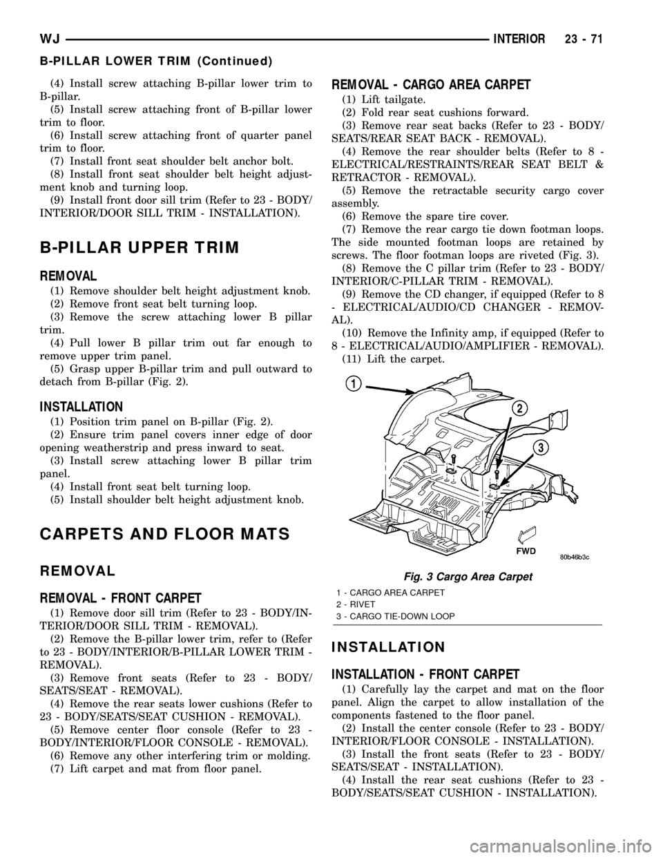
(7) Remove the rear cargo tie down footman loops.
The side mounted footman loops are retained by
screws. The floor footman loops are riveted (Fig. 3).
(8) Remove the C pillar trim (Refer to 23 - BODY/
INTERIOR/C-PILLAR TRIM - REMOVAL).
(9) Remove the CD changer, if equipped (Refer to 8
- ELECTRICAL/AUDIO/CD CHANGER - REMOV-
AL).
(10) Remove the Infinity amp, if equipped (Refer to
8 - ELECTRICAL/AUDIO/AMPLIFIER - REMOVAL).
(11) Lift the carpet.
INSTALLATION
INSTALLATION - FRONT CARPET
(1) Carefully lay the carpet and mat on the floor
panel. Align the carpet to allow installation of the
components fastened to the floor panel.
(2) Install the center console (Refer to 23 - BODY/
INTERIOR/FLOOR CONSOLE - INSTALLATION).
(3) Install the front seats (Refer to 23 - BODY/
SEATS/SEAT - INSTALLATION).
(4) Install the rear seat cushions (Refer to 23 -
BODY/SEATS/SEAT CUSHION - INSTALLATION).
Fig. 3 Cargo Area Carpet
1 - CARGO AREA CARPET
2 - RIVET
3 - CARGO TIE-DOWN LOOP
WJINTERIOR 23 - 71
B-PILLAR LOWER TRIM (Continued)
Page 1945 of 2199
(5) Install the lower B pillar trim (Refer to 23 -
BODY/INTERIOR/B-PILLAR LOWER TRIM -
INSTALLATION).
(6) Install the door sill trim (Refer to 23 - BODY/
INTERIOR/DOOR SILL TRIM - INSTALLATION).
(7) Install any other moldings or trim panels
removed.
INSTALLATION - CARGO AREA CARPET
(1) Thoroughly clean the area with Mopar Super
Kleent, or equivalent.
(2) Lay the new carpet in.
(3) Install the ªCº pillar trim (Refer to 23 - BODY/
INTERIOR/C-PILLAR TRIM - INSTALLATION).
(4) Install the CD changer, if equipped (Refer to 8 -
ELECTRICAL/AUDIO/CD CHANGER - INSTALLA-
TION).
(5) Install the footman loops (Fig. 3).
(6) Install the rear shoulder belts (Refer to 8 -
ELECTRICAL/RESTRAINTS/REAR SEAT BELT &
RETRACTOR - INSTALLATION).
(7) Install the rear seat backs (Refer to 23 -
BODY/SEATS/REAR SEAT BACK - INSTALLA-
TION).
(8) Install the Infinity amp, if equipped (Refer to 8
- ELECTRICAL/AUDIO/AMPLIFIER - INSTALLA-
TION).
(9) Install the spare tire cover.
(10) Install the retractable security cover.
COWL TRIM
REMOVAL
(1) Remove front door sill trim (Refer to 23 -
BODY/INTERIOR/DOOR SILL TRIM - REMOVAL).
(2) Remove screws attaching cowl trim to floor.
(3) Remove plastic nut.
(4) Grasp cowl trim and pull outward to separate
from clip.
(5) Separate cowl trim from vehicle.
INSTALLATION
(1) Position cowl trim and press into place.
(2) Install screws attaching cowl trim to floor.
(3) Install plastic nut.
(4) Install front door sill trim (Refer to 23 - BODY/
INTERIOR/DOOR SILL TRIM - INSTALLATION).
C-PILLAR TRIM
REMOVAL
(1) Remove rear shoulder belt turning loop.
(2) Remove rear shoulder belt height adjustment
knob.
(3) Remove screws attaching quarter panel trim.
(4) Pull quarter panel trim outward as necessary.
(5) Grasp C-pillar upper trim and pull outward to
disengage from C-pillar (Fig. 4).
(6) Route rear shoulder belt through access hole.
(7) Separate C-pillar upper trim from vehicle.
INSTALLATION
(1) Position C-pillar upper trim at C-pillar (Fig. 4).
(2) Route rear shoulder belt through access hole.
(3) Press C-pillar upper trim onto C-pillar.
(4) Press quarter panel trim into place as neces-
sary.
(5) Ensure front edge of trim is covered by weath-
erstrip.
(6) Install screws attaching quarter panel trim.
(7) Install rear shoulder belt height adjustment
knob.
(8) Install rear shoulder belt turning loop.
23 - 72 INTERIORWJ
CARPETS AND FLOOR MATS (Continued)
Page 1949 of 2199
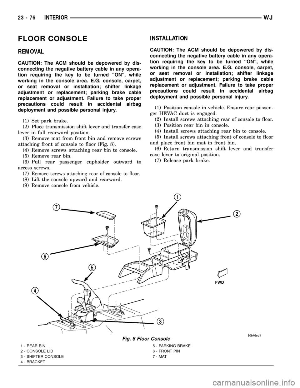
FLOOR CONSOLE
REMOVAL
CAUTION: The ACM should be depowered by dis-
connecting the negative battery cable in any opera-
tion requiring the key to be turned ªONº, while
working in the console area. E.G. console, carpet,
or seat removal or installation; shifter linkage
adjustment or replacement; parking brake cable
replacement or adjustment. Failure to take proper
precautions could result in accidental airbag
deployment and possible personal injury.
(1) Set park brake.
(2) Place transmission shift lever and transfer case
lever in full rearward position.
(3) Remove mat from front bin and remove screws
attaching front of console to floor (Fig. 8).
(4) Remove screws attaching rear bin to console.
(5) Remove rear bin.
(6) Pull rear passenger cupholder outward to
access screws.
(7)
Remove screws attaching rear of console to floor.
(8) Lift the console upward and rearward.
(9) Remove console from vehicle.
INSTALLATION
CAUTION: The ACM should be depowered by dis-
connecting the negative battery cable in any opera-
tion requiring the key to be turned ªONº, while
working in the console area. E.G. console, carpet,
or seat removal or installation; shifter linkage
adjustment or replacement; parking brake cable
replacement or adjustment. Failure to take proper
precautions could result in accidental airbag
deployment and possible personal injury.
(1) Position console in vehicle. Ensure rear passen-
ger HEVAC duct is engaged.
(2) Install screws attaching rear of console to floor.
(3) Position rear bin in console.
(4) Install screws attaching rear bin to console.
(5) Install screws attaching front of console to floor
and place front bin mat in front bin.
(6) Return transmission shift lever and transfer
case lever to original position.
(7) Release park brake.
Fig. 8 Floor Console
1 - REAR BIN
2 - CONSOLE LID
3 - SHIFTER CONSOLE
4 - BRACKET5 - PARKING BRAKE
6 - FRONT PIN
7-MAT
23 - 76 INTERIORWJ
Page 1950 of 2199
HEADLINER
REMOVAL
CAUTION: The headliner is a one-piece, molded
component. It has limited flexibility and must not be
bent. Damage may possibly result.
(1) Record radio presets and disconnect negative
battery cable.
(2) Remove A pillar trim moldings (Refer to 23 -
BODY/INTERIOR/A-PILLAR TRIM - REMOVAL).
(3) Remove B pillar upper trim moldings (Refer to
23 - BODY/INTERIOR/B-PILLAR UPPER TRIM -
REMOVAL).
(4) Remove C pillar trim moldings (Refer to 23 -
BODY/INTERIOR/C-PILLAR TRIM - REMOVAL).
(5) Remove D pillar trim molding (Refer to 23 -
BODY/INTERIOR/D-PILLAR TRIM - REMOVAL).
(6) Remove the sun visors (Refer to 23 - BODY/IN-
TERIOR/SUN VISOR - REMOVAL).
(7) Disconnect the vanity lamp electrical connector.
(8) Remove assist handles from roof rails (Refer to
23 - BODY/INTERIOR/ASSIST HANDLE - REMOV-
AL).
(9) Remove dome lamp and overhead console, if
equipped.
(10) Remove rear cargo/dome lamp.
(11) Remove sun roof pinch welt, if equipped.
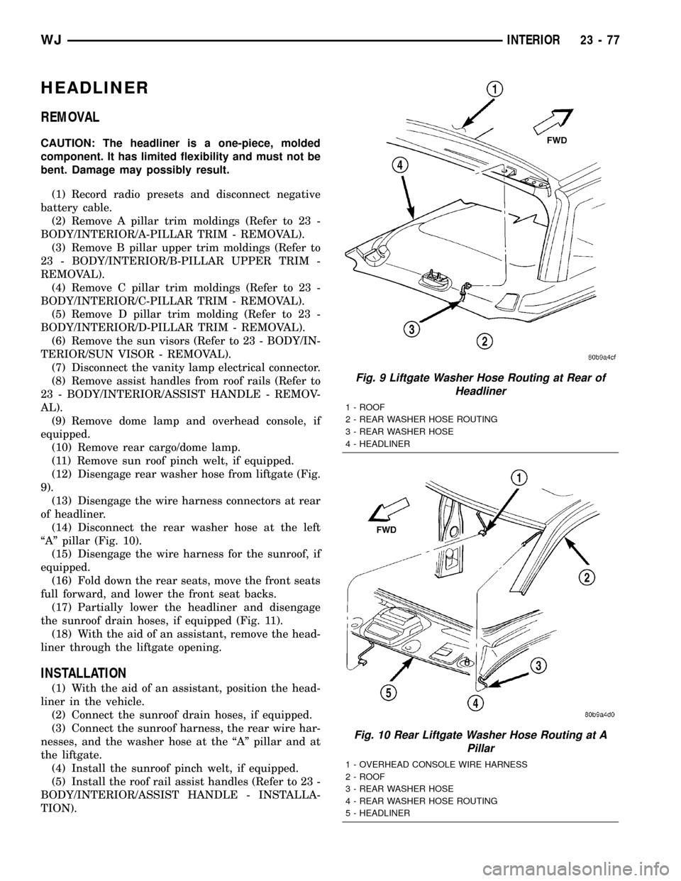
(12) Disengage rear washer hose from liftgate (Fig.
9).
(13) Disengage the wire harness connectors at rear
of headliner.
(14) Disconnect the rear washer hose at the left
ªAº pillar (Fig. 10).
(15) Disengage the wire harness for the sunroof, if
equipped.
(16) Fold down the rear seats, move the front seats
full forward, and lower the front seat backs.
(17) Partially lower the headliner and disengage
the sunroof drain hoses, if equipped (Fig. 11).
(18) With the aid of an assistant, remove the head-
liner through the liftgate opening.
INSTALLATION
(1) With the aid of an assistant, position the head-
liner in the vehicle.
(2) Connect the sunroof drain hoses, if equipped.
(3) Connect the sunroof harness, the rear wire har-
nesses, and the washer hose at the ªAº pillar and at
the liftgate.
(4) Install the sunroof pinch welt, if equipped.
(5) Install the roof rail assist handles (Refer to 23 -
BODY/INTERIOR/ASSIST HANDLE - INSTALLA-
TION).
Fig. 9 Liftgate Washer Hose Routing at Rear of
Headliner
1 - ROOF
2 - REAR WASHER HOSE ROUTING
3 - REAR WASHER HOSE
4 - HEADLINER
Fig. 10 Rear Liftgate Washer Hose Routing at A
Pillar
1 - OVERHEAD CONSOLE WIRE HARNESS
2 - ROOF
3 - REAR WASHER HOSE
4 - REAR WASHER HOSE ROUTING
5 - HEADLINER
WJINTERIOR 23 - 77
Page 1952 of 2199
LIFTGATE OPENING UPPER
TRIM
REMOVAL
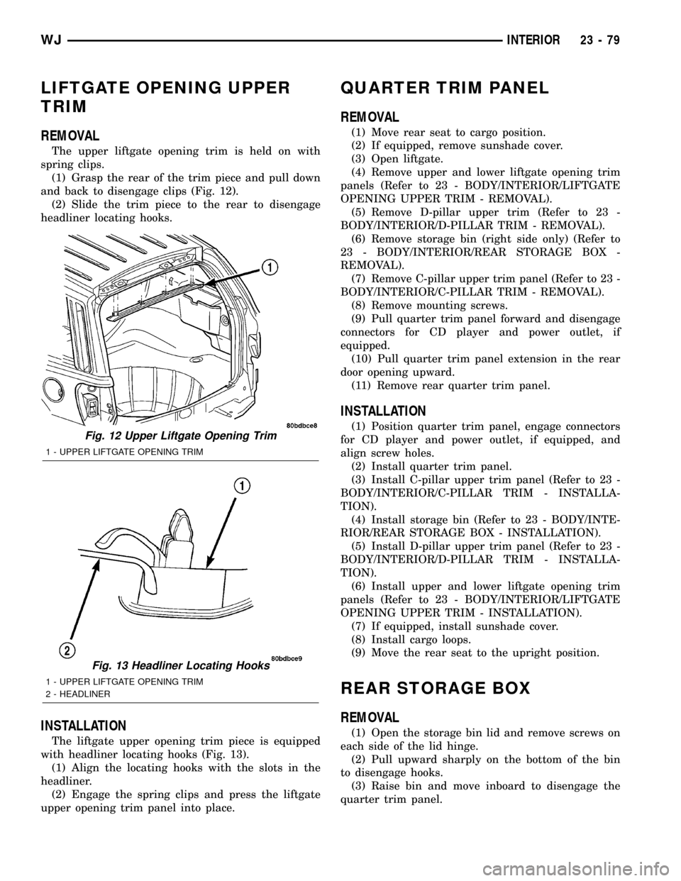
The upper liftgate opening trim is held on with
spring clips.
(1) Grasp the rear of the trim piece and pull down
and back to disengage clips (Fig. 12).
(2) Slide the trim piece to the rear to disengage
headliner locating hooks.
INSTALLATION
The liftgate upper opening trim piece is equipped
with headliner locating hooks (Fig. 13).
(1) Align the locating hooks with the slots in the
headliner.
(2) Engage the spring clips and press the liftgate
upper opening trim panel into place.
QUARTER TRIM PANEL
REMOVAL
(1) Move rear seat to cargo position.
(2) If equipped, remove sunshade cover.
(3) Open liftgate.
(4) Remove upper and lower liftgate opening trim
panels (Refer to 23 - BODY/INTERIOR/LIFTGATE
OPENING UPPER TRIM - REMOVAL).
(5) Remove D-pillar upper trim (Refer to 23 -
BODY/INTERIOR/D-PILLAR TRIM - REMOVAL).
(6) Remove storage bin (right side only) (Refer to
23 - BODY/INTERIOR/REAR STORAGE BOX -
REMOVAL).
(7) Remove C-pillar upper trim panel (Refer to 23 -
BODY/INTERIOR/C-PILLAR TRIM - REMOVAL).
(8) Remove mounting screws.
(9) Pull quarter trim panel forward and disengage
connectors for CD player and power outlet, if
equipped.
(10) Pull quarter trim panel extension in the rear
door opening upward.
(11) Remove rear quarter trim panel.
INSTALLATION
(1) Position quarter trim panel, engage connectors
for CD player and power outlet, if equipped, and
align screw holes.
(2) Install quarter trim panel.
(3) Install C-pillar upper trim panel (Refer to 23 -
BODY/INTERIOR/C-PILLAR TRIM - INSTALLA-
TION).
(4) Install storage bin (Refer to 23 - BODY/INTE-
RIOR/REAR STORAGE BOX - INSTALLATION).
(5) Install D-pillar upper trim panel (Refer to 23 -
BODY/INTERIOR/D-PILLAR TRIM - INSTALLA-
TION).
(6) Install upper and lower liftgate opening trim
panels (Refer to 23 - BODY/INTERIOR/LIFTGATE
OPENING UPPER TRIM - INSTALLATION).
(7) If equipped, install sunshade cover.
(8) Install cargo loops.
(9) Move the rear seat to the upright position.
REAR STORAGE BOX
REMOVAL
(1) Open the storage bin lid and remove screws on
each side of the lid hinge.
(2) Pull upward sharply on the bottom of the bin
to disengage hooks.
(3) Raise bin and move inboard to disengage the
quarter trim panel.
Fig. 12 Upper Liftgate Opening Trim
1 - UPPER LIFTGATE OPENING TRIM
Fig. 13 Headliner Locating Hooks
1 - UPPER LIFTGATE OPENING TRIM
2 - HEADLINER
WJINTERIOR 23 - 79
Page 1958 of 2199
INSTALLATION
(1) Position seat on floor pan.
(2) If equipped, connect power seat wire harness
connector.
(3) Install rear bolts attaching seat to floor pan.
Tighten bolts to 40 N´m (30 ft. lbs.) torque.
(4) If equipped, install cover on seat track.
(5) Move seat to full rearward position.
(6) Install front bolts attaching seat to floor pan.
Tighten bolts to 40 N´m (30 ft. lbs.) torque.
FRONT SEAT BACK
REMOVAL
(1) Move seat to full rearward position.
(2) Remove inboard bolt attaching seat back frame
to seat cushion frame.
(3) Move seat to full forward position.
(4) Move seat back to full recline position.
(5) Remove screws attaching seat side shield to
seat frame.
(6) Disconnect wire harness connector from
recliner motor, if equipped.
(7) From the underside of the seat, disconnect the
wire harness connector for the power lumber and/or
heated seat, if equipped.
(8) Remove outboard bolts attaching recliner to
seat cushion frame.
(9) Route the power lumber and/or heated seat
harness through the seat cushion cover, if equipped.
(10) Separate seat back from seat cushion.
INSTALLATION
(1) Position seat back on seat cushion.
(2) Route the power lumber and heater harness
through the seat cushion cover, if equipped.
(3) Install recliner bolts attaching seat back frame
to seat cushion frame. Tighten bolts to 28 N´m (20 ft.
lbs.) torque.
(4) Install the inboard bolt attaching seat back
frame to seat cushion frame. Tighten bolt to 47N´m
(35 ft.lbs.).
(5) Connect wire harness connector to recliner
motor and/or heated seat, if equipped.
(6) From the underside of the seat, connect the
power lumber and/or heated seat wire harness con-
nector to the seat harness, if equipped.
(7) Install screws attaching seat side shield to seat
frame.
FRONT SEAT BACK COVER
REMOVAL
(1) Remove head restraint (Refer to 23 - BODY/
SEATS/FRONT HEADREST - REMOVAL).
(2) Using a trim stick, carefully pry head restraint
release button caps from the top of seat back.
(3) Remove seat back (Refer to 23 - BODY/SEATS/
FRONT SEAT BACK - REMOVAL).
(4) Disengage J-strap at base of seat back.
(5) Slide hand between the face of the seat back
pad and the cushion cover and carefully separate
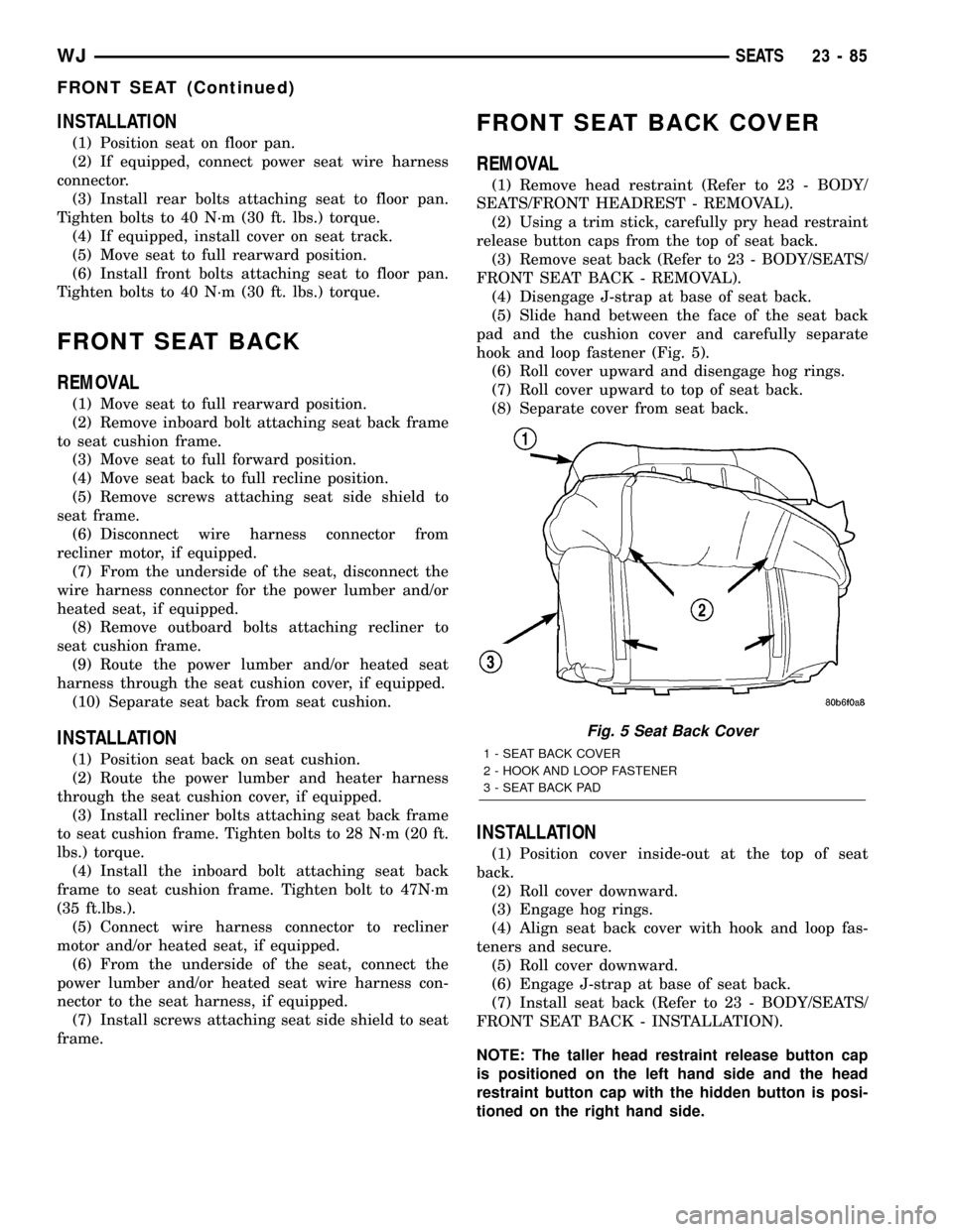
hook and loop fastener (Fig. 5).
(6) Roll cover upward and disengage hog rings.
(7) Roll cover upward to top of seat back.
(8) Separate cover from seat back.
INSTALLATION
(1) Position cover inside-out at the top of seat
back.
(2) Roll cover downward.
(3) Engage hog rings.
(4) Align seat back cover with hook and loop fas-
teners and secure.
(5) Roll cover downward.
(6) Engage J-strap at base of seat back.
(7) Install seat back (Refer to 23 - BODY/SEATS/
FRONT SEAT BACK - INSTALLATION).
NOTE: The taller head restraint release button cap
is positioned on the left hand side and the head
restraint button cap with the hidden button is posi-
tioned on the right hand side.
Fig. 5 Seat Back Cover
1 - SEAT BACK COVER
2 - HOOK AND LOOP FASTENER
3 - SEAT BACK PAD
WJSEATS 23 - 85
FRONT SEAT (Continued)