2002 JEEP GRAND CHEROKEE trans
[x] Cancel search: transPage 2150 of 2199

moisture which may have netered and become
trapped within the refrigerant system. In addition,
during periods of high demand air conditioner opera-
tion, the filter-drier acts as a reservoir to store sur-
plus refrigerant. Refrigerant enters the filter-drier as
a high-pressure, low-temperature liquid.
REMOVAL
WARNING: REVIEW THE WARNINGS AND CAU-
TIONS IN THE FRONT OF THIS SECTION BEFORE
PERFORMING THE FOLLOWING OPERATION.
(Refer to 24 - HEATING & AIR CONDITIONING/
PLUMBING - WARNING) (Refer to 24 - HEATING &
AIR CONDITIONING/PLUMBING - CAUTION)
(1) Recover the refrigerant from the refrigerant
system(Refer to 24 - HEATING & AIR CONDITION-
ING/PLUMBING - STANDARD PROCEDURE).
(2) Remove the battery and the battery tray(Refer
to 8 - ELECTRICAL/BATTERY SYSTEM/BATTERY -
REMOVAL) and (Refer to 8 - ELECTRICAL/BAT-
TERY SYSTEM/TRAY - REMOVAL).
(3) Remove the screw from the receiver/drier
bracket (Fig. 15) or (Fig. 16).
(4) Remove the retaining nut from the evaporator
connection and then slide the suction line off the
stud and liquid line.
(5) Remove the receiver/drier bracket from the
stud and disconnect the liquid line from the evapora-tor inlet. Install plugs in or tape over all of the evap-
orator connection openings and opened refrigerant
line fittings.
(6) Disconnect the liquid line from the condenser
outlet. Install plugs in, or tape over all of the opened
refrigerant line fittings.
(7) Remove liquid line assembly.
INSTALLATION
WARNING: REVIEW THE WARNINGS AND CAU-
TIONS IN THE FRONT OF THIS SECTION BEFORE
PERFORMING THE FOLLOWING OPERATION.
(Refer to 24 - HEATING & AIR CONDITIONING/
PLUMBING - WARNING) (Refer to 24 - HEATING &
AIR CONDITIONING/PLUMBING - CAUTION)
Any kinks or sharp bends in the refrigerant plumb-
ing will reduce the capacity of the entire air condi-
tioning system. Kinks and sharp bends reduce the
flow of refrigerant in the system. A good rule for the
flexible hose refrigerant lines is to keep the radius of
all bends at least ten times the diameter of the hose.
In addition, the flexible hose refrigerant lines should
be routed so they are at least 80 millimeters (3
inches) from the exhaust manifold.
High pressures are produced in the refrigerant sys-
tem when the air conditioning compressor is operat-
ing. Extreme care must be exercised to make sure
that each of the refrigerant system connections is
pressure-tight and leak free. It is a good practice to
Fig. 14 HEATER CORE, TUBES, AND O-RINGS
1 - HEATER CORE TUBES
2 - TUBE-TO-CORE CLAMPS
3 - SCREWS
4 - O-RINGS
5 - HEATER CORE
Fig. 15 COMPRESSOR AND A/C LINES - V8
1 - DISCHARGE LINE
2 - A/C COMPRESSOR
3 - SUCTION LINE
4 - A/C/ CONDENSOR
5 - DISCHARGE LINE TO CONDENSOR
6 - A/C PRESSURE TRANSDUCER SWITCH
7 - A/C/ SERVICE PORT
8 - RECEIVER DRIER
WJPLUMBING 24 - 73
RECEIVER / DRIER (Continued)
Page 2153 of 2199

VISCOUS HEATER
DESCRIPTION
DESCRIPTION
The diesel engine has an engine mounted mechan-
ical device called a Viscous Heater that is used to
heat the coolant coming from the engine to the
heater core. The Viscous Heater is driven by the
engine fan belt and has a electro-mechanical clutch
which is controlled by the HVAC control unit.
DESCRIPTION - VISCOUS HEATER CLUTCH
The basic viscous heater clutch assembly consists
of a stationary electromagnetic coil, a hub bearing
and pulley assembly and a clutch plate. The electro-
magnetic coil unit and the hub bearing and pulley
assembly are each retained on the nose of the com-
pressor front housing with snap rings (Fig. 17). The
clutch plate is keyed to the viscous heater shaft and
secured with a nut. These components provide the
means to engage and disengage the viscous heater
from the engine accessory drive belt.
OPERATION
OPERATION - VISCOUS HEATER
The Viscous Heater is driven by the engine fan
belt. The Viscous Heater has an electro-mechanical
clutch that receives a signal from the HVAC control
head and the Viscous Heater controller that ener-
gizes and engages the clutch. Once engaged theclutch allows the Viscous Heater to increase the tem-
perature of the coolant flowing to the heater core,
which provides heat the passenger compartment
quicker than normal engines without the Viscous
Heater. The Viscous Heater generates heat by means
of friction which heats a special Silicon Oil within its
housing which is then transferred to the engine cool-
ant when the coolant passes over fins within the
pump. Please note that the coolant is isolated from
the silicon oil within the pump housing. When
demand for passenger compartment heat decreases
the Viscous Heater clutch will receive an input from
the Viscous heater controller to disengage.
OPERATION - VISCOUS HEATER CLUTCH
When the clutch coil is energized, it magnetically
draws the clutch into contact with the pulley and
drives the viscous heater shaft. When the coil is not
energized the pulley freewheels on the clutch hub
bearing, which is part of the pulley. The viscous
heater clutch and coil are the only serviced parts on
the viscous heater assembly. If the viscous heater is
inoperative or damaged the entire assembly must be
replaced. The viscous heater clutch engagement is
controlled by several components: the viscous heater
controller, the engine powertrain control module and
the HVAC control head.
REMOVAL
REMOVAL - VISCOUS HEATER
(1) Drain the engine coolant(Refer to 7 - COOL-
ING/ENGINE - STANDARD PROCEDURE).
(2) Remove the engine accessory drive belt(Refer to
7 - COOLING/ACCESSORY DRIVE/DRIVE BELTS -
REMOVAL).
(3) Remove the heater hose clamps at the Viscous
Heater.
(4) Remove the heater hoses from the Viscous
Heater.
(5) Unplug the Viscous Heater clutch electrical
connector.
(6) Remove the bolts holding the Viscous Heater to
the mounting bracket.
(7) Remove the Viscous Heater from the vehicle.
REMOVAL - VISCOUS HEATER CLUTCH
(1) The viscous heater clutch can be serviced in
the vehicle and the cooling system does not have to
be drained.
(2) Disconnect and isolate the battery negative
cable.
(3) Remove the serpentine drive belt(Refer to 7 -
COOLING/ACCESSORY DRIVE/DRIVE BELTS -
REMOVAL).
Fig. 17 CLUTCH ASSEMBLY- typical
1 - CLUTCH PLATE
2 - SHAFT KEY
3 - PULLEY
4 - COIL
5 - CLUTCH SHIMS
6 - SNAP RING
7 - SNAP RING
24 - 76 PLUMBINGWJ
Page 2161 of 2199
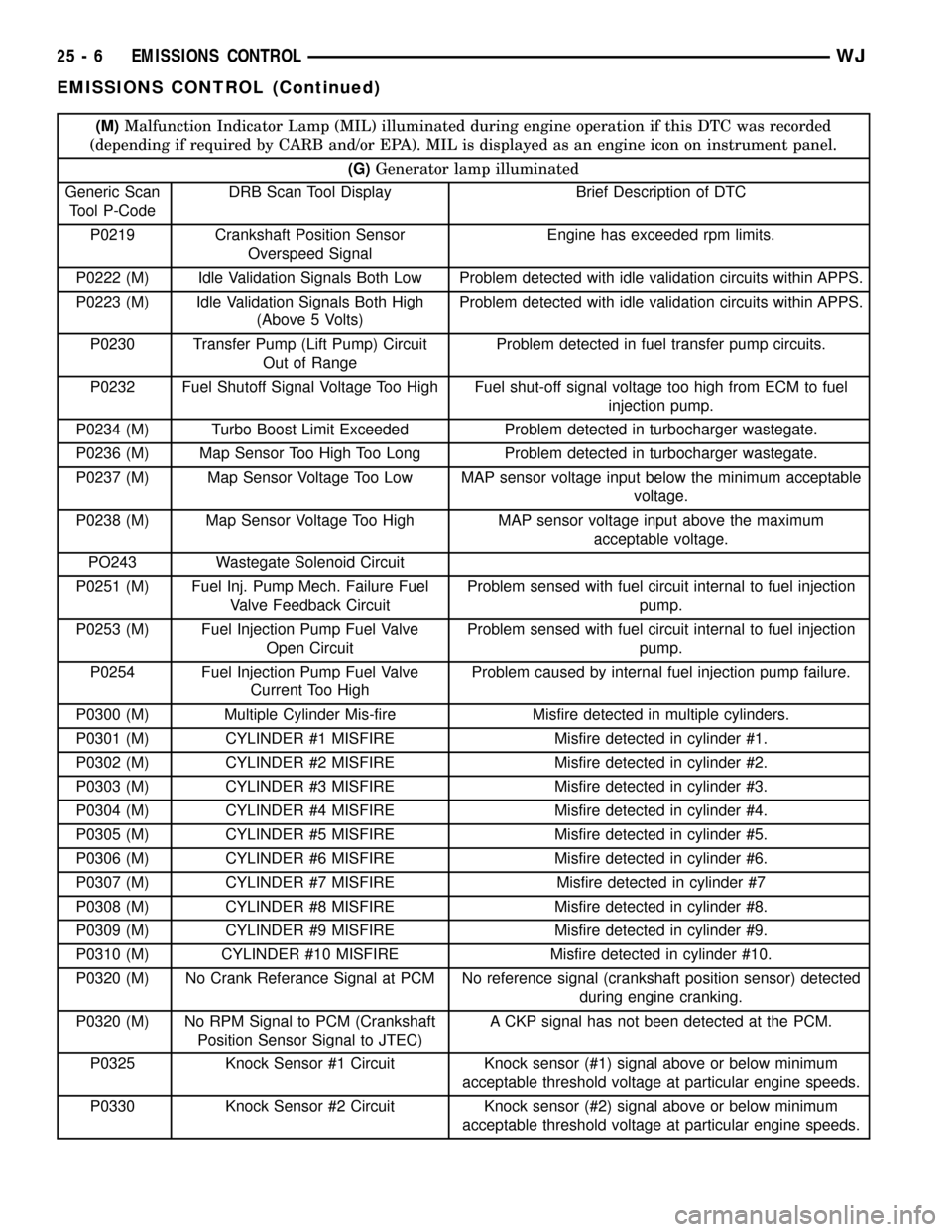
(M)Malfunction Indicator Lamp (MIL) illuminated during engine operation if this DTC was recorded
(depending if required by CARB and/or EPA). MIL is displayed as an engine icon on instrument panel.
(G)Generator lamp illuminated
Generic Scan
Tool P-CodeDRB Scan Tool Display Brief Description of DTC
P0219 Crankshaft Position Sensor
Overspeed SignalEngine has exceeded rpm limits.
P0222 (M) Idle Validation Signals Both Low Problem detected with idle validation circuits within APPS.
P0223 (M) Idle Validation Signals Both High
(Above 5 Volts)Problem detected with idle validation circuits within APPS.
P0230 Transfer Pump (Lift Pump) Circuit
Out of RangeProblem detected in fuel transfer pump circuits.
P0232 Fuel Shutoff Signal Voltage Too High Fuel shut-off signal voltage too high from ECM to fuel
injection pump.
P0234 (M) Turbo Boost Limit Exceeded Problem detected in turbocharger wastegate.
P0236 (M) Map Sensor Too High Too Long Problem detected in turbocharger wastegate.
P0237 (M) Map Sensor Voltage Too Low MAP sensor voltage input below the minimum acceptable
voltage.
P0238 (M) Map Sensor Voltage Too High MAP sensor voltage input above the maximum
acceptable voltage.
PO243 Wastegate Solenoid Circuit
P0251 (M) Fuel Inj. Pump Mech. Failure Fuel
Valve Feedback CircuitProblem sensed with fuel circuit internal to fuel injection
pump.
P0253 (M) Fuel Injection Pump Fuel Valve
Open CircuitProblem sensed with fuel circuit internal to fuel injection
pump.
P0254 Fuel Injection Pump Fuel Valve
Current Too HighProblem caused by internal fuel injection pump failure.
P0300 (M) Multiple Cylinder Mis-fire Misfire detected in multiple cylinders.
P0301 (M) CYLINDER #1 MISFIRE Misfire detected in cylinder #1.
P0302 (M) CYLINDER #2 MISFIRE Misfire detected in cylinder #2.
P0303 (M) CYLINDER #3 MISFIRE Misfire detected in cylinder #3.
P0304 (M) CYLINDER #4 MISFIRE Misfire detected in cylinder #4.
P0305 (M) CYLINDER #5 MISFIRE Misfire detected in cylinder #5.
P0306 (M) CYLINDER #6 MISFIRE Misfire detected in cylinder #6.
P0307 (M) CYLINDER #7 MISFIRE Misfire detected in cylinder #7
P0308 (M) CYLINDER #8 MISFIRE Misfire detected in cylinder #8.
P0309 (M) CYLINDER #9 MISFIRE Misfire detected in cylinder #9.
P0310 (M) CYLINDER #10 MISFIRE Misfire detected in cylinder #10.
P0320 (M) No Crank Referance Signal at PCM No reference signal (crankshaft position sensor) detected
during engine cranking.
P0320 (M) No RPM Signal to PCM (Crankshaft
Position Sensor Signal to JTEC)A CKP signal has not been detected at the PCM.
P0325 Knock Sensor #1 Circuit Knock sensor (#1) signal above or below minimum
acceptable threshold voltage at particular engine speeds.
P0330 Knock Sensor #2 Circuit Knock sensor (#2) signal above or below minimum
acceptable threshold voltage at particular engine speeds.
25 - 6 EMISSIONS CONTROLWJ
EMISSIONS CONTROL (Continued)
Page 2164 of 2199
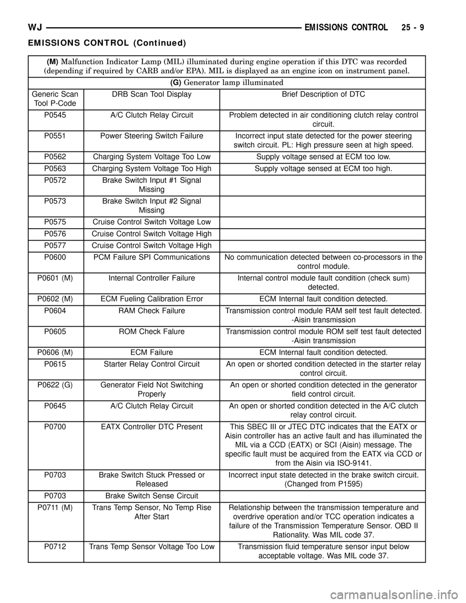
(M)Malfunction Indicator Lamp (MIL) illuminated during engine operation if this DTC was recorded
(depending if required by CARB and/or EPA). MIL is displayed as an engine icon on instrument panel.
(G)Generator lamp illuminated
Generic Scan
Tool P-CodeDRB Scan Tool Display Brief Description of DTC
P0545 A/C Clutch Relay Circuit Problem detected in air conditioning clutch relay control
circuit.
P0551 Power Steering Switch Failure Incorrect input state detected for the power steering
switch circuit. PL: High pressure seen at high speed.
P0562 Charging System Voltage Too Low Supply voltage sensed at ECM too low.
P0563 Charging System Voltage Too High Supply voltage sensed at ECM too high.
P0572 Brake Switch Input #1 Signal
Missing
P0573 Brake Switch Input #2 Signal
Missing
P0575 Cruise Control Switch Voltage Low
P0576 Cruise Control Switch Voltage High
P0577 Cruise Control Switch Voltage High
P0600 PCM Failure SPI Communications No communication detected between co-processors in the
control module.
P0601 (M) Internal Controller Failure Internal control module fault condition (check sum)
detected.
P0602 (M) ECM Fueling Calibration Error ECM Internal fault condition detected.
P0604 RAM Check Failure Transmission control module RAM self test fault detected.
-Aisin transmission
P0605 ROM Check Falure Transmission control module ROM self test fault detected
-Aisin transmission
P0606 (M) ECM Failure ECM Internal fault condition detected.
P0615 Starter Relay Control Circuit An open or shorted condition detected in the starter relay
control circuit.
P0622 (G) Generator Field Not Switching
ProperlyAn open or shorted condition detected in the generator
field control circuit.
P0645 A/C Clutch Relay Circuit An open or shorted condition detected in the A/C clutch
relay control circuit.
P0700 EATX Controller DTC Present This SBEC III or JTEC DTC indicates that the EATX or
Aisin controller has an active fault and has illuminated the
MIL via a CCD (EATX) or SCI (Aisin) message. The
specific fault must be acquired from the EATX via CCD or
from the Aisin via ISO-9141.
P0703 Brake Switch Stuck Pressed or
ReleasedIncorrect input state detected in the brake switch circuit.
(Changed from P1595)
P0703 Brake Switch Sense Circuit
P0711 (M) Trans Temp Sensor, No Temp Rise
After StartRelationship between the transmission temperature and
overdrive operation and/or TCC operation indicates a
failure of the Transmission Temperature Sensor. OBD II
Rationality. Was MIL code 37.
P0712 Trans Temp Sensor Voltage Too Low Transmission fluid temperature sensor input below
acceptable voltage. Was MIL code 37.
WJEMISSIONS CONTROL 25 - 9
EMISSIONS CONTROL (Continued)
Page 2165 of 2199
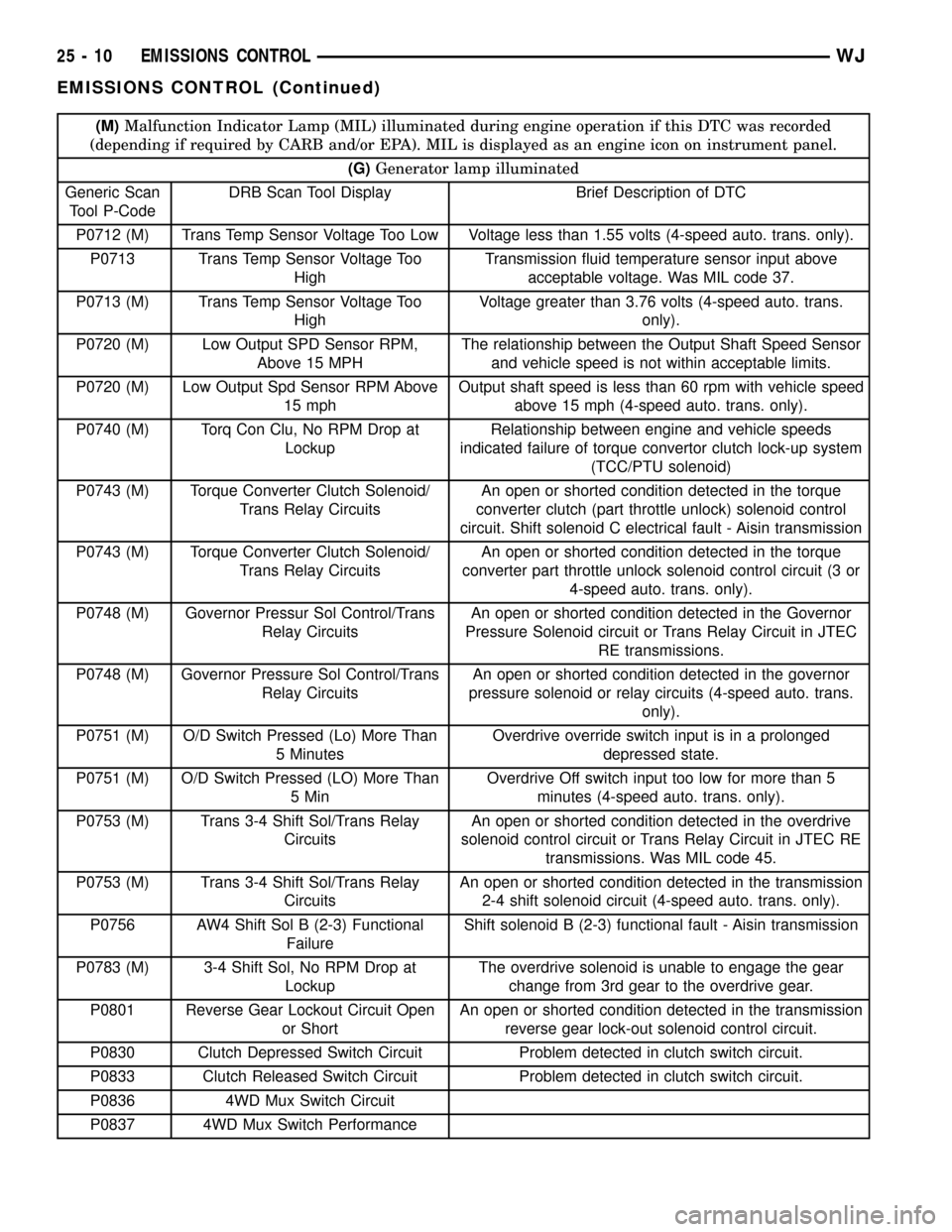
(M)Malfunction Indicator Lamp (MIL) illuminated during engine operation if this DTC was recorded
(depending if required by CARB and/or EPA). MIL is displayed as an engine icon on instrument panel.
(G)Generator lamp illuminated
Generic Scan
Tool P-CodeDRB Scan Tool Display Brief Description of DTC
P0712 (M) Trans Temp Sensor Voltage Too Low Voltage less than 1.55 volts (4-speed auto. trans. only).
P0713 Trans Temp Sensor Voltage Too
HighTransmission fluid temperature sensor input above
acceptable voltage. Was MIL code 37.
P0713 (M) Trans Temp Sensor Voltage Too
HighVoltage greater than 3.76 volts (4-speed auto. trans.
only).
P0720 (M) Low Output SPD Sensor RPM,
Above 15 MPHThe relationship between the Output Shaft Speed Sensor
and vehicle speed is not within acceptable limits.
P0720 (M) Low Output Spd Sensor RPM Above
15 mphOutput shaft speed is less than 60 rpm with vehicle speed
above 15 mph (4-speed auto. trans. only).
P0740 (M) Torq Con Clu, No RPM Drop at
LockupRelationship between engine and vehicle speeds
indicated failure of torque convertor clutch lock-up system
(TCC/PTU solenoid)
P0743 (M) Torque Converter Clutch Solenoid/
Trans Relay CircuitsAn open or shorted condition detected in the torque
converter clutch (part throttle unlock) solenoid control
circuit. Shift solenoid C electrical fault - Aisin transmission
P0743 (M) Torque Converter Clutch Solenoid/
Trans Relay CircuitsAn open or shorted condition detected in the torque
converter part throttle unlock solenoid control circuit (3 or
4-speed auto. trans. only).
P0748 (M) Governor Pressur Sol Control/Trans
Relay CircuitsAn open or shorted condition detected in the Governor
Pressure Solenoid circuit or Trans Relay Circuit in JTEC
RE transmissions.
P0748 (M) Governor Pressure Sol Control/Trans
Relay CircuitsAn open or shorted condition detected in the governor
pressure solenoid or relay circuits (4-speed auto. trans.
only).
P0751 (M) O/D Switch Pressed (Lo) More Than
5 MinutesOverdrive override switch input is in a prolonged
depressed state.
P0751 (M) O/D Switch Pressed (LO) More Than
5 MinOverdrive Off switch input too low for more than 5
minutes (4-speed auto. trans. only).
P0753 (M) Trans 3-4 Shift Sol/Trans Relay
CircuitsAn open or shorted condition detected in the overdrive
solenoid control circuit or Trans Relay Circuit in JTEC RE
transmissions. Was MIL code 45.
P0753 (M) Trans 3-4 Shift Sol/Trans Relay
CircuitsAn open or shorted condition detected in the transmission
2-4 shift solenoid circuit (4-speed auto. trans. only).
P0756 AW4 Shift Sol B (2-3) Functional
FailureShift solenoid B (2-3) functional fault - Aisin transmission
P0783 (M) 3-4 Shift Sol, No RPM Drop at
LockupThe overdrive solenoid is unable to engage the gear
change from 3rd gear to the overdrive gear.
P0801 Reverse Gear Lockout Circuit Open
or ShortAn open or shorted condition detected in the transmission
reverse gear lock-out solenoid control circuit.
P0830 Clutch Depressed Switch Circuit Problem detected in clutch switch circuit.
P0833 Clutch Released Switch Circuit Problem detected in clutch switch circuit.
P0836 4WD Mux Switch Circuit
P0837 4WD Mux Switch Performance
25 - 10 EMISSIONS CONTROLWJ
EMISSIONS CONTROL (Continued)
Page 2168 of 2199
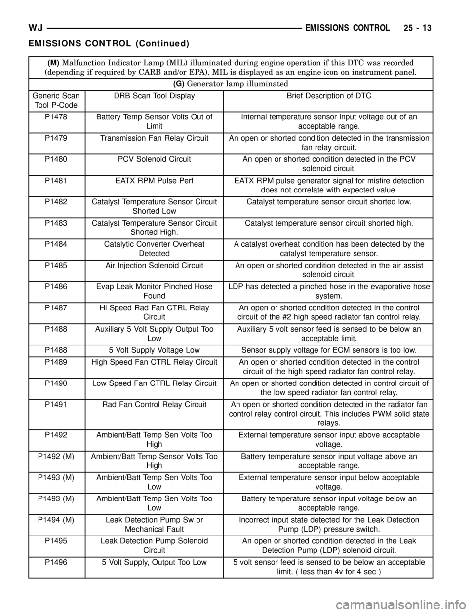
(M)Malfunction Indicator Lamp (MIL) illuminated during engine operation if this DTC was recorded
(depending if required by CARB and/or EPA). MIL is displayed as an engine icon on instrument panel.
(G)Generator lamp illuminated
Generic Scan
Tool P-CodeDRB Scan Tool Display Brief Description of DTC
P1478 Battery Temp Sensor Volts Out of
LimitInternal temperature sensor input voltage out of an
acceptable range.
P1479 Transmission Fan Relay Circuit An open or shorted condition detected in the transmission
fan relay circuit.
P1480 PCV Solenoid Circuit An open or shorted condition detected in the PCV
solenoid circuit.
P1481 EATX RPM Pulse Perf EATX RPM pulse generator signal for misfire detection
does not correlate with expected value.
P1482 Catalyst Temperature Sensor Circuit
Shorted LowCatalyst temperature sensor circuit shorted low.
P1483 Catalyst Temperature Sensor Circuit
Shorted High.Catalyst temperature sensor circuit shorted high.
P1484 Catalytic Converter Overheat
DetectedA catalyst overheat condition has been detected by the
catalyst temperature sensor.
P1485 Air Injection Solenoid Circuit An open or shorted condition detected in the air assist
solenoid circuit.
P1486 Evap Leak Monitor Pinched Hose
FoundLDP has detected a pinched hose in the evaporative hose
system.
P1487 Hi Speed Rad Fan CTRL Relay
CircuitAn open or shorted condition detected in the control
circuit of the #2 high speed radiator fan control relay.
P1488 Auxiliary 5 Volt Supply Output Too
LowAuxiliary 5 volt sensor feed is sensed to be below an
acceptable limit.
P1488 5 Volt Supply Voltage Low Sensor supply voltage for ECM sensors is too low.
P1489 High Speed Fan CTRL Relay Circuit An open or shorted condition detected in the control
circuit of the high speed radiator fan control relay.
P1490 Low Speed Fan CTRL Relay Circuit An open or shorted condition detected in control circuit of
the low speed radiator fan control relay.
P1491 Rad Fan Control Relay Circuit An open or shorted condition detected in the radiator fan
control relay control circuit. This includes PWM solid state
relays.
P1492 Ambient/Batt Temp Sen Volts Too
HighExternal temperature sensor input above acceptable
voltage.
P1492 (M) Ambient/Batt Temp Sensor Volts Too
HighBattery temperature sensor input voltage above an
acceptable range.
P1493 (M) Ambient/Batt Temp Sen Volts Too
LowExternal temperature sensor input below acceptable
voltage.
P1493 (M) Ambient/Batt Temp Sen Volts Too
LowBattery temperature sensor input voltage below an
acceptable range.
P1494 (M) Leak Detection Pump Sw or
Mechanical FaultIncorrect input state detected for the Leak Detection
Pump (LDP) pressure switch.
P1495 Leak Detection Pump Solenoid
CircuitAn open or shorted condition detected in the Leak
Detection Pump (LDP) solenoid circuit.
P1496 5 Volt Supply, Output Too Low 5 volt sensor feed is sensed to be below an acceptable
limit. ( less than 4v for 4 sec )
WJEMISSIONS CONTROL 25 - 13
EMISSIONS CONTROL (Continued)
Page 2170 of 2199
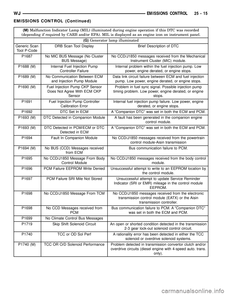
(M)Malfunction Indicator Lamp (MIL) illuminated during engine operation if this DTC was recorded
(depending if required by CARB and/or EPA). MIL is displayed as an engine icon on instrument panel.
(G)Generator lamp illuminated
Generic Scan
Tool P-CodeDRB Scan Tool Display Brief Description of DTC
P1687 No MIC BUS Message (No Cluster
BUS Message)No CCD/J1850 messages received from the Mechanical
Instrument Cluster (MIC) module.
P1688 (M) Internal Fuel Injection Pump
Controller FailureInternal problem within the fuel injection pump. Low
power, engine derated, or engine stops.
P1689 (M) No Communication Between ECM
and Injection Pump ModuleData link circuit failure between ECM and fuel injection
pump. Low power, engine derated, or engine stops.
P1690 (M) Fuel Injection Pump CKP Sensor
Does Not Agree With ECM CKP
SensorProblem in fuel sync signal. Possible injection pump
timing problem. Low power, engine derated, or engine
stops.
P1691 Fuel Injection Pump Controller
Calibration ErrorInternal fuel injection pump failure. Low power, engine
derated, or engine stops.
P1692 DTC Set In ECM A9Companion DTC9was set in both the ECM and PCM.
P1693 (M) DTC Detected in Companion Module A fault has been generated in the companion engine
control module.
P1693 (M) DTC Detected in PCM/ECM or DTC
Detected in ECMA9Companion DTC9was set in both the ECM and PCM.
P1694 Fault In Companion Module No CCD/J1850 messages received from the powertrain
control module-Aisin transmission
P1694 (M) No BUS (CCD) Messages received
from ECMBus communication failure to PCM.
P1695 No CCD/J1850 Message From Body
Control ModuleNo CCD/J1850 messages received from the body control
module.
P1696 PCM Failure EEPROM Write Denied Unsuccessful attempt to write to an EEPROM location by
the control module.
P1697 PCM Failure SRI Mile Not Stored Unsuccessful attempt to update Service Reminder
Indicator (SRI or EMR) mileage in the control module
EEPROM.
P1698 No CCD/J1850 Message From TCM No CCD/J1850 messages received from the electronic
transmission control module (EATX) or the Aisin
transmission controller.
P1698 No CCD Messages received from
PCMBus communication failure to PCM. A9Companion DTC9
was set in both the ECM and PCM.
P1699 No Climate Control Bus Messages
P1719 Skip Shift Solenoid Circuit An open or shorted condition detected in the transmission
2-3 gear lock-out solenoid control circuit.
P1740 TCC or OD Sol Perf A rationality error has been detected in either the TCC
solenoid or overdrive solenoid systems.
P1740 (M) TCC OR O/D Solenoid Performance Problem detected in transmission convertor clutch and/or
overdrive circuits (diesel engine with 4-speed auto. trans.
only).
WJEMISSIONS CONTROL 25 - 15
EMISSIONS CONTROL (Continued)
Page 2171 of 2199
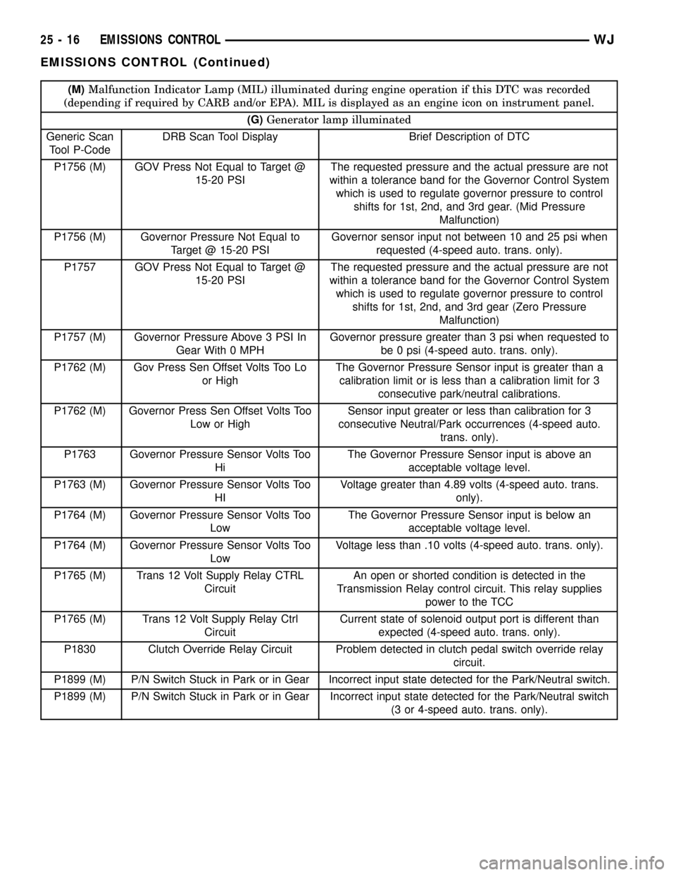
(M)Malfunction Indicator Lamp (MIL) illuminated during engine operation if this DTC was recorded
(depending if required by CARB and/or EPA). MIL is displayed as an engine icon on instrument panel.
(G)Generator lamp illuminated
Generic Scan
Tool P-CodeDRB Scan Tool Display Brief Description of DTC
P1756 (M) GOV Press Not Equal to Target @
15-20 PSIThe requested pressure and the actual pressure are not
within a tolerance band for the Governor Control System
which is used to regulate governor pressure to control
shifts for 1st, 2nd, and 3rd gear. (Mid Pressure
Malfunction)
P1756 (M) Governor Pressure Not Equal to
Target @ 15-20 PSIGovernor sensor input not between 10 and 25 psi when
requested (4-speed auto. trans. only).
P1757 GOV Press Not Equal to Target @
15-20 PSIThe requested pressure and the actual pressure are not
within a tolerance band for the Governor Control System
which is used to regulate governor pressure to control
shifts for 1st, 2nd, and 3rd gear (Zero Pressure
Malfunction)
P1757 (M) Governor Pressure Above 3 PSI In
Gear With 0 MPHGovernor pressure greater than 3 psi when requested to
be 0 psi (4-speed auto. trans. only).
P1762 (M) Gov Press Sen Offset Volts Too Lo
or HighThe Governor Pressure Sensor input is greater than a
calibration limit or is less than a calibration limit for 3
consecutive park/neutral calibrations.
P1762 (M) Governor Press Sen Offset Volts Too
Low or HighSensor input greater or less than calibration for 3
consecutive Neutral/Park occurrences (4-speed auto.
trans. only).
P1763 Governor Pressure Sensor Volts Too
HiThe Governor Pressure Sensor input is above an
acceptable voltage level.
P1763 (M) Governor Pressure Sensor Volts Too
HIVoltage greater than 4.89 volts (4-speed auto. trans.
only).
P1764 (M) Governor Pressure Sensor Volts Too
LowThe Governor Pressure Sensor input is below an
acceptable voltage level.
P1764 (M) Governor Pressure Sensor Volts Too
LowVoltage less than .10 volts (4-speed auto. trans. only).
P1765 (M) Trans 12 Volt Supply Relay CTRL
CircuitAn open or shorted condition is detected in the
Transmission Relay control circuit. This relay supplies
power to the TCC
P1765 (M) Trans 12 Volt Supply Relay Ctrl
CircuitCurrent state of solenoid output port is different than
expected (4-speed auto. trans. only).
P1830 Clutch Override Relay Circuit Problem detected in clutch pedal switch override relay
circuit.
P1899 (M) P/N Switch Stuck in Park or in Gear Incorrect input state detected for the Park/Neutral switch.
P1899 (M) P/N Switch Stuck in Park or in Gear Incorrect input state detected for the Park/Neutral switch
(3 or 4-speed auto. trans. only).
25 - 16 EMISSIONS CONTROLWJ
EMISSIONS CONTROL (Continued)