2002 JEEP GRAND CHEROKEE seats
[x] Cancel search: seatsPage 1686 of 2199
²pressure adjusting screw and bracket assembly
²throttle lever
²manual lever and shaft seal
²throttle lever shaft seal, washer, and E-clip
²fluid filter and screws
²detent ball and spring
²valve body screws
²governor pressure solenoid
²governor pressure sensor and retaining clip
²park lock rod and E-clip
ASSEMBLY
CAUTION: Do not force valves or plugs into place
during reassembly. If the valve body bores, valves
and plugs are free of distortion or burrs, the valve
body components should all slide into place easily.
In addition, do not overtighten the transfer plate
and valve body screws during reassembly. Over-
tightening can distort the housings resulting in
valve sticking, cross leakage and unsatisfactory
operation. Tighten valve body screws to recom-
mended torque only.
LOWER HOUSING
(1) Lubricate valves, springs, and the housing
valve and plug bores with clean transmission fluid
(Fig. 309).
(2) Install 3-4 timing valve spring and valve in
lower housing.
(3) Install 3-4 quick fill valve in lower housing.
(4) Install 3-4 quick fill valve spring and plug in
housing.
(5) Install timing valve end plate. Tighten end
plate screws to 4 N´m (35 in. lbs.) torque.
3-4 ACCUMULATOR
(1) Lubricate accumulator piston, seals and hous-
ing piston bore with clean transmission fluid (Fig.
310).
(2) Install new seal rings on accumulator piston.
(3) Install piston and spring in housing.
(4) Install end plate on housing.
TRANSFER PLATE
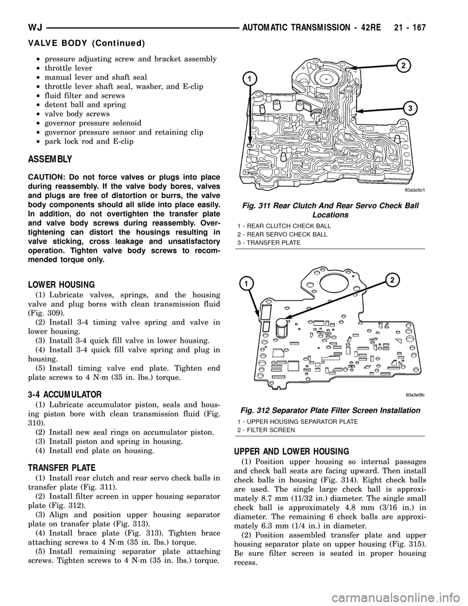
(1) Install rear clutch and rear servo check balls in
transfer plate (Fig. 311).
(2) Install filter screen in upper housing separator
plate (Fig. 312).
(3) Align and position upper housing separator
plate on transfer plate (Fig. 313).
(4) Install brace plate (Fig. 313). Tighten brace
attaching screws to 4 N´m (35 in. lbs.) torque.
(5) Install remaining separator plate attaching
screws. Tighten screws to 4 N´m (35 in. lbs.) torque.
UPPER AND LOWER HOUSING
(1) Position upper housing so internal passages
and check ball seats are facing upward. Then install
check balls in housing (Fig. 314). Eight check balls
are used. The single large check ball is approxi-
mately 8.7 mm (11/32 in.) diameter. The single small
check ball is approximately 4.8 mm (3/16 in.) in
diameter. The remaining 6 check balls are approxi-
mately 6.3 mm (1/4 in.) in diameter.
(2) Position assembled transfer plate and upper
housing separator plate on upper housing (Fig. 315).
Be sure filter screen is seated in proper housing
recess.
Fig. 311 Rear Clutch And Rear Servo Check Ball
Locations
1 - REAR CLUTCH CHECK BALL
2 - REAR SERVO CHECK BALL
3 - TRANSFER PLATE
Fig. 312 Separator Plate Filter Screen Installation
1 - UPPER HOUSING SEPARATOR PLATE
2 - FILTER SCREEN
WJAUTOMATIC TRANSMISSION - 42RE 21 - 167
VALVE BODY (Continued)
Page 1829 of 2199
FLUID
STANDARD PROCEDURE - FLUID DRAIN/
REFILL
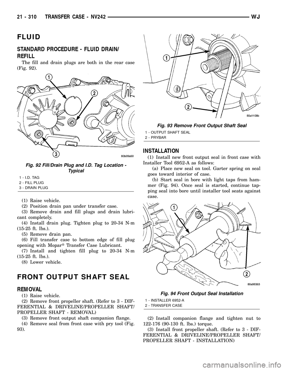
The fill and drain plugs are both in the rear case
(Fig. 92).
(1) Raise vehicle.
(2) Position drain pan under transfer case.
(3) Remove drain and fill plugs and drain lubri-
cant completely.
(4) Install drain plug. Tighten plug to 20-34 N´m
(15-25 ft. lbs.).
(5) Remove drain pan.
(6) Fill transfer case to bottom edge of fill plug
opening with MopartTransfer Case Lubricant.
(7) Install and tighten fill plug to 20-34 N´m
(15-25 ft. lbs.).
(8) Lower vehicle.
FRONT OUTPUT SHAFT SEAL
REMOVAL
(1) Raise vehicle.
(2) Remove front propeller shaft. (Refer to 3 - DIF-
FERENTIAL & DRIVELINE/PROPELLER SHAFT/
PROPELLER SHAFT - REMOVAL)
(3) Remove front output shaft companion flange.
(4) Remove seal from front case with pry tool (Fig.
93).
INSTALLATION
(1) Install new front output seal in front case with
Installer Tool 6952-A as follows:
(a) Place new seal on tool. Garter spring on seal
goes toward interior of case.
(b) Start seal in bore with light taps from ham-
mer (Fig. 94). Once seal is started, continue tap-
ping seal into bore until installer tool seats against
case.
(2) Install companion flange and tighten nut to
122-176 (90-130 ft. lbs.) torque.
(3) Install front propeller shaft. (Refer to 3 - DIF-
FERENTIAL & DRIVELINE/PROPELLER SHAFT/
PROPELLER SHAFT - INSTALLATION)
Fig. 92 Fill/Drain Plug and I.D. Tag Location -
Typical
1 - I.D. TAG
2 - FILL PLUG
3 - DRAIN PLUG
Fig. 93 Remove Front Output Shaft Seal
1 - OUTPUT SHAFT SEAL
2 - PRYBAR
Fig. 94 Front Output Seal Installation
1 - INSTALLER 6952-A
2 - TRANSFER CASE
21 - 310 TRANSFER CASE - NV242WJ
Page 1831 of 2199
REMOVAL
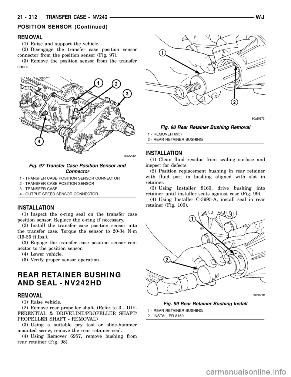
(1) Raise and support the vehicle.
(2) Disengage the transfer case position sensor
connector from the position sensor (Fig. 97).
(3) Remove the position sensor from the transfer
case.
INSTALLATION
(1) Inspect the o-ring seal on the transfer case
position sensor. Replace the o-ring if necessary.
(2) Install the transfer case position sensor into
the transfer case. Torque the sensor to 20-34 N´m
(15-25 ft.lbs.).
(3) Engage the transfer case position sensor con-
nector to the position sensor.
(4) Lower vehicle.
(5) Verify proper sensor operation.
REAR RETAINER BUSHING
AND SEAL - NV242HD
REMOVAL
(1) Raise vehicle.
(2) Remove rear propeller shaft. (Refer to 3 - DIF-
FERENTIAL & DRIVELINE/PROPELLER SHAFT/
PROPELLER SHAFT - REMOVAL)
(3) Using a suitable pry tool or slide-hammer
mounted screw, remove the rear retainer seal.
(4) Using Remover 6957, remove bushing from
rear retainer (Fig. 98).
INSTALLATION
(1) Clean fluid residue from sealing surface and
inspect for defects.
(2) Position replacement bushing in rear retainer
with fluid port in bushing aligned with slot in
retainer.
(3) Using Installer 8160, drive bushing into
retainer until installer seats against case (Fig. 99).
(4) Using Installer C-3995-A, install seal in rear
retainer (Fig. 100).
Fig. 97 Transfer Case Position Sensor and
Connector
1 - TRANSFER CASE POSITION SENSOR CONNECTOR
2 - TRANSFER CASE POSITION SENSOR
3 - TRANSFER CASE
4 - OUTPUT SPEED SENSOR CONNECTOR
Fig. 98 Rear Retainer Bushing Removal
1 - REMOVER 6957
2 - REAR RETAINER BUSHING
Fig. 99 Rear Retainer Bushing Install
1 - REAR RETAINER BUSHING
2 - INSTALLER 8160
21 - 312 TRANSFER CASE - NV242WJ
POSITION SENSOR (Continued)
Page 1857 of 2199
FLUID
STANDARD PROCEDURE - FLUID DRAIN/
REFILL
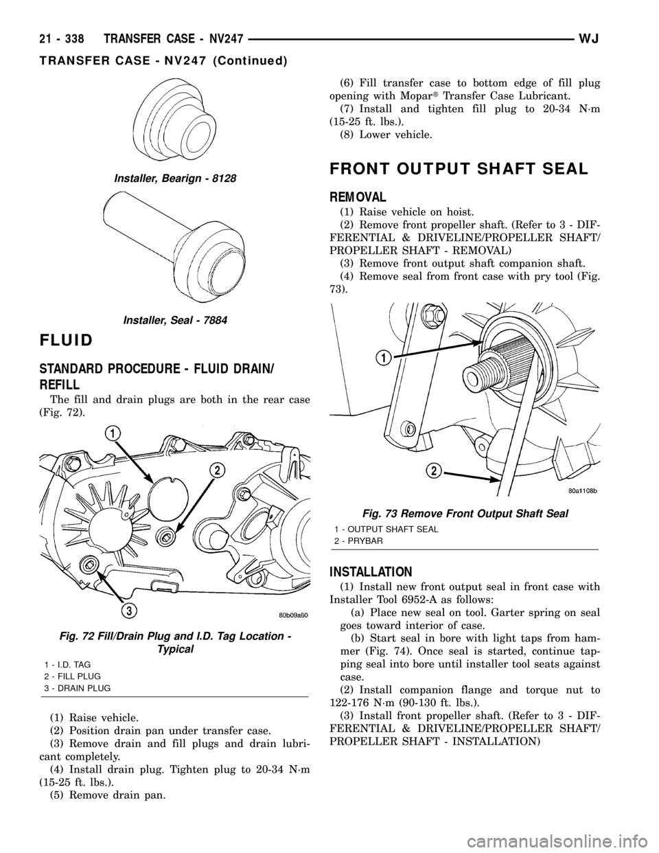
The fill and drain plugs are both in the rear case
(Fig. 72).
(1) Raise vehicle.
(2) Position drain pan under transfer case.
(3) Remove drain and fill plugs and drain lubri-
cant completely.
(4) Install drain plug. Tighten plug to 20-34 N´m
(15-25 ft. lbs.).
(5) Remove drain pan.(6) Fill transfer case to bottom edge of fill plug
opening with MopartTransfer Case Lubricant.
(7) Install and tighten fill plug to 20-34 N´m
(15-25 ft. lbs.).
(8) Lower vehicle.
FRONT OUTPUT SHAFT SEAL
REMOVAL
(1) Raise vehicle on hoist.
(2) Remove front propeller shaft. (Refer to 3 - DIF-
FERENTIAL & DRIVELINE/PROPELLER SHAFT/
PROPELLER SHAFT - REMOVAL)
(3) Remove front output shaft companion shaft.
(4) Remove seal from front case with pry tool (Fig.
73).
INSTALLATION
(1) Install new front output seal in front case with
Installer Tool 6952-A as follows:
(a) Place new seal on tool. Garter spring on seal
goes toward interior of case.
(b) Start seal in bore with light taps from ham-
mer (Fig. 74). Once seal is started, continue tap-
ping seal into bore until installer tool seats against
case.
(2) Install companion flange and torque nut to
122-176 N´m (90-130 ft. lbs.).
(3) Install front propeller shaft. (Refer to 3 - DIF-
FERENTIAL & DRIVELINE/PROPELLER SHAFT/
PROPELLER SHAFT - INSTALLATION)
Installer, Bearign - 8128
Installer, Seal - 7884
Fig. 72 Fill/Drain Plug and I.D. Tag Location -
Typical
1 - I.D. TAG
2 - FILL PLUG
3 - DRAIN PLUG
Fig. 73 Remove Front Output Shaft Seal
1 - OUTPUT SHAFT SEAL
2 - PRYBAR
21 - 338 TRANSFER CASE - NV247WJ
TRANSFER CASE - NV247 (Continued)
Page 1858 of 2199
REAR RETAINER BUSHING
AND SEAL
REMOVAL
(1) Raise vehicle on hoist.
(2) Remove rear propeller shaft. (Refer to 3 - DIF-
FERENTIAL & DRIVELINE/PROPELLER SHAFT/
PROPELLER SHAFT - REMOVAL)
(3) Using a suitable pry tool or slide-hammer
mounted screw, remove the rear retainer seal.
(4) Using Remover 6957, remove bushing from
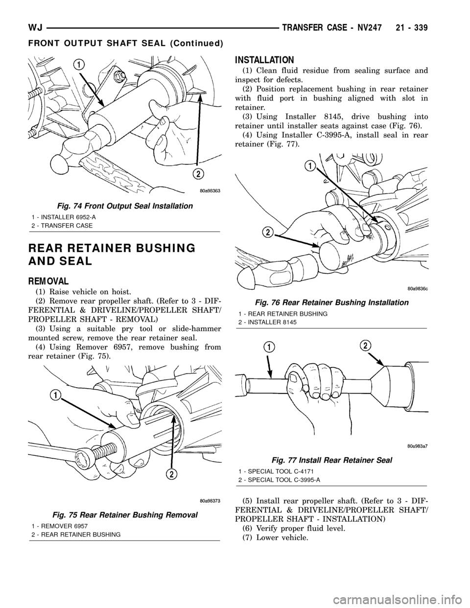
rear retainer (Fig. 75).
INSTALLATION
(1) Clean fluid residue from sealing surface and
inspect for defects.
(2) Position replacement bushing in rear retainer
with fluid port in bushing aligned with slot in
retainer.
(3) Using Installer 8145, drive bushing into
retainer until installer seats against case (Fig. 76).
(4) Using Installer C-3995-A, install seal in rear
retainer (Fig. 77).
(5) Install rear propeller shaft. (Refer to 3 - DIF-
FERENTIAL & DRIVELINE/PROPELLER SHAFT/
PROPELLER SHAFT - INSTALLATION)
(6) Verify proper fluid level.
(7) Lower vehicle.
Fig. 74 Front Output Seal Installation
1 - INSTALLER 6952-A
2 - TRANSFER CASE
Fig. 75 Rear Retainer Bushing Removal
1 - REMOVER 6957
2 - REAR RETAINER BUSHING
Fig. 76 Rear Retainer Bushing Installation
1 - REAR RETAINER BUSHING
2 - INSTALLER 8145
Fig. 77 Install Rear Retainer Seal
1 - SPECIAL TOOL C-4171
2 - SPECIAL TOOL C-3995-A
WJTRANSFER CASE - NV247 21 - 339
FRONT OUTPUT SHAFT SEAL (Continued)
Page 1874 of 2199
BODY
TABLE OF CONTENTS
page page
BODY
DIAGNOSIS AND TESTING
WATER LEAKS........................1
WIND NOISE..........................2
STANDARD PROCEDURE
STANDARD PROCEDURE - BODY
LUBRICATION.........................2
STANDARD PROCEDURE - DRILLING AND
WELDING............................3
SPECIFICATIONS
BODY LUBRICANTS....................3
SPECIFICATIONS - TORQUE.............4
SPECIAL TOOLS
BODY...............................4DECKLID/HATCH/LIFTGATE/TAILGATE........5
DOOR - FRONT.........................11
DOORS - REAR.........................19
EXTERIOR.............................25
HOOD.................................33
INSTRUMENT PANEL SYSTEM.............36
INTERIOR..............................69
PAINT.................................81
SEATS................................83
STATIONARY GLASS.....................93
SUNROOF.............................96
WEATHERSTRIP/SEALS..................105
BODY STRUCTURE.....................112
BODY
DIAGNOSIS AND TESTING
WATER LEAKS
Water leaks can be caused by poor sealing,
improper body component alignment, body seam
porosity, missing plugs, or blocked drain holes. Cen-
trifugal and gravitational force can cause water to
drip from a location away from the actual leak point,
making leak detection difficult. All body sealing
points should be water tight in normal wet-driving
conditions. Water flowing downward from the front of
the vehicle should not enter the passenger or luggage
compartment. Moving sealing surfaces will not
always seal water tight under all conditions. At
times, side glass or door seals will allow water to
enter the passenger compartment during high pres-
sure washing or hard driving rain (severe) condi-
tions. Overcompensating on door or glass
adjustments to stop a water leak that occurs under
severe conditions can cause premature seal wear and
excessive closing or latching effort. After completing
a repair, water test vehicle to verify leak has stopped
before returning vehicle to use.
VISUAL INSPECTION BEFORE WATER LEAK TESTS
Verify that floor and body plugs are in place, body
drains are clear, and body components are properly
aligned and sealed. If component alignment or seal-
ing is necessary, refer to the appropriate section of
this group for proper procedures.
WATER LEAK TESTS
WARNING: DO NOT USE ELECTRIC SHOP LIGHTS
OR TOOLS IN WATER TEST AREA. PERSONAL
INJURY CAN RESULT.
When the conditions causing a water leak have
been determined, simulate the conditions as closely
as possible.
²If a leak occurs with the vehicle parked in a
steady light rain, flood the leak area with an open-
ended garden hose.
²If a leak occurs while driving at highway speeds
in a steady rain, test the leak area with a reasonable
velocity stream or fan spray of water. Direct the
spray in a direction comparable to actual conditions.
²If a leak occurs when the vehicle is parked on an
incline, hoist the end or side of the vehicle to simu-
late this condition. This method can be used when
the leak occurs when the vehicle accelerates, stops or
turns. If the leak occurs on acceleration, hoist the
front of the vehicle. If the leak occurs when braking,
hoist the back of the vehicle. If the leak occurs on left
turns, hoist the left side of the vehicle. If the leak
occurs on right turns, hoist the right side of the vehi-
cle. For hoisting recommendations refer to Group 0,
Lubrication and Maintenance, General Information
section.
WATER LEAK DETECTION
To detect a water leak point-of-entry, do a water
test and watch for water tracks or droplets forming
on the inside of the vehicle. If necessary, remove inte-
rior trim covers or panels to gain visual access to the
WJBODY 23 - 1
Page 1944 of 2199

(4) Install screw attaching B-pillar lower trim to
B-pillar.
(5) Install screw attaching front of B-pillar lower
trim to floor.
(6) Install screw attaching front of quarter panel
trim to floor.
(7) Install front seat shoulder belt anchor bolt.
(8) Install front seat shoulder belt height adjust-
ment knob and turning loop.
(9) Install front door sill trim (Refer to 23 - BODY/
INTERIOR/DOOR SILL TRIM - INSTALLATION).
B-PILLAR UPPER TRIM
REMOVAL
(1) Remove shoulder belt height adjustment knob.
(2) Remove front seat belt turning loop.
(3) Remove the screw attaching lower B pillar
trim.
(4) Pull lower B pillar trim out far enough to
remove upper trim panel.
(5) Grasp upper B-pillar trim and pull outward to
detach from B-pillar (Fig. 2).
INSTALLATION
(1) Position trim panel on B-pillar (Fig. 2).
(2) Ensure trim panel covers inner edge of door
opening weatherstrip and press inward to seat.
(3) Install screw attaching lower B pillar trim
panel.
(4) Install front seat belt turning loop.
(5) Install shoulder belt height adjustment knob.
CARPETS AND FLOOR MATS
REMOVAL
REMOVAL - FRONT CARPET
(1) Remove door sill trim (Refer to 23 - BODY/IN-
TERIOR/DOOR SILL TRIM - REMOVAL).
(2) Remove the B-pillar lower trim, refer to (Refer
to 23 - BODY/INTERIOR/B-PILLAR LOWER TRIM -
REMOVAL).
(3) Remove front seats (Refer to 23 - BODY/
SEATS/SEAT - REMOVAL).
(4) Remove the rear seats lower cushions (Refer to
23 - BODY/SEATS/SEAT CUSHION - REMOVAL).
(5) Remove center floor console (Refer to 23 -
BODY/INTERIOR/FLOOR CONSOLE - REMOVAL).
(6) Remove any other interfering trim or molding.
(7) Lift carpet and mat from floor panel.
REMOVAL - CARGO AREA CARPET
(1) Lift tailgate.
(2) Fold rear seat cushions forward.
(3) Remove rear seat backs (Refer to 23 - BODY/
SEATS/REAR SEAT BACK - REMOVAL).
(4) Remove the rear shoulder belts (Refer to 8 -
ELECTRICAL/RESTRAINTS/REAR SEAT BELT &
RETRACTOR - REMOVAL).
(5) Remove the retractable security cargo cover
assembly.
(6) Remove the spare tire cover.
(7) Remove the rear cargo tie down footman loops.
The side mounted footman loops are retained by
screws. The floor footman loops are riveted (Fig. 3).
(8) Remove the C pillar trim (Refer to 23 - BODY/
INTERIOR/C-PILLAR TRIM - REMOVAL).
(9) Remove the CD changer, if equipped (Refer to 8
- ELECTRICAL/AUDIO/CD CHANGER - REMOV-
AL).
(10) Remove the Infinity amp, if equipped (Refer to
8 - ELECTRICAL/AUDIO/AMPLIFIER - REMOVAL).
(11) Lift the carpet.
INSTALLATION
INSTALLATION - FRONT CARPET
(1) Carefully lay the carpet and mat on the floor
panel. Align the carpet to allow installation of the
components fastened to the floor panel.
(2) Install the center console (Refer to 23 - BODY/
INTERIOR/FLOOR CONSOLE - INSTALLATION).
(3) Install the front seats (Refer to 23 - BODY/
SEATS/SEAT - INSTALLATION).
(4) Install the rear seat cushions (Refer to 23 -
BODY/SEATS/SEAT CUSHION - INSTALLATION).
Fig. 3 Cargo Area Carpet
1 - CARGO AREA CARPET
2 - RIVET
3 - CARGO TIE-DOWN LOOP
WJINTERIOR 23 - 71
B-PILLAR LOWER TRIM (Continued)
Page 1945 of 2199

(5) Install the lower B pillar trim (Refer to 23 -
BODY/INTERIOR/B-PILLAR LOWER TRIM -
INSTALLATION).
(6) Install the door sill trim (Refer to 23 - BODY/
INTERIOR/DOOR SILL TRIM - INSTALLATION).
(7) Install any other moldings or trim panels
removed.
INSTALLATION - CARGO AREA CARPET
(1) Thoroughly clean the area with Mopar Super
Kleent, or equivalent.
(2) Lay the new carpet in.
(3) Install the ªCº pillar trim (Refer to 23 - BODY/
INTERIOR/C-PILLAR TRIM - INSTALLATION).
(4) Install the CD changer, if equipped (Refer to 8 -
ELECTRICAL/AUDIO/CD CHANGER - INSTALLA-
TION).
(5) Install the footman loops (Fig. 3).
(6) Install the rear shoulder belts (Refer to 8 -
ELECTRICAL/RESTRAINTS/REAR SEAT BELT &
RETRACTOR - INSTALLATION).
(7) Install the rear seat backs (Refer to 23 -
BODY/SEATS/REAR SEAT BACK - INSTALLA-
TION).
(8) Install the Infinity amp, if equipped (Refer to 8
- ELECTRICAL/AUDIO/AMPLIFIER - INSTALLA-
TION).
(9) Install the spare tire cover.
(10) Install the retractable security cover.
COWL TRIM
REMOVAL
(1) Remove front door sill trim (Refer to 23 -
BODY/INTERIOR/DOOR SILL TRIM - REMOVAL).
(2) Remove screws attaching cowl trim to floor.
(3) Remove plastic nut.
(4) Grasp cowl trim and pull outward to separate
from clip.
(5) Separate cowl trim from vehicle.
INSTALLATION
(1) Position cowl trim and press into place.
(2) Install screws attaching cowl trim to floor.
(3) Install plastic nut.
(4) Install front door sill trim (Refer to 23 - BODY/
INTERIOR/DOOR SILL TRIM - INSTALLATION).
C-PILLAR TRIM
REMOVAL
(1) Remove rear shoulder belt turning loop.
(2) Remove rear shoulder belt height adjustment
knob.
(3) Remove screws attaching quarter panel trim.
(4) Pull quarter panel trim outward as necessary.
(5) Grasp C-pillar upper trim and pull outward to
disengage from C-pillar (Fig. 4).
(6) Route rear shoulder belt through access hole.
(7) Separate C-pillar upper trim from vehicle.
INSTALLATION
(1) Position C-pillar upper trim at C-pillar (Fig. 4).
(2) Route rear shoulder belt through access hole.
(3) Press C-pillar upper trim onto C-pillar.
(4) Press quarter panel trim into place as neces-
sary.
(5) Ensure front edge of trim is covered by weath-
erstrip.
(6) Install screws attaching quarter panel trim.
(7) Install rear shoulder belt height adjustment
knob.
(8) Install rear shoulder belt turning loop.
23 - 72 INTERIORWJ
CARPETS AND FLOOR MATS (Continued)