2002 JEEP GRAND CHEROKEE Outlet
[x] Cancel search: OutletPage 1428 of 2199
OPERATION
Voltage to operate the electric pump is supplied
through the fuel pump relay.
Fuel is drawn in through a filter at the bottom of
the module and pushed through the electric motor
gearset to the pump outlet.
Check Valve Operation:The pump outlet con-
tains a one-way check valve to prevent fuel flow back
into the tank and to maintain fuel supply line pres-
sure (engine warm) when pump is not operational. It
is also used to keep the fuel supply line full of gaso-
line when pump is not operational. After the vehicle
has cooled down, fuel pressure may drop to 0 psi
(cold fluid contracts), but liquid gasoline will remain
in fuel supply line between the check valve and fuel
injectors.Fuel pressure that has dropped to 0
psi on a cooled down vehicle (engine off) is a
normal condition.Refer to the Fuel Pressure Leak
Down Test for more information.
The electric fuel pump is not a separate, service-
able component.
DIAGNOSIS AND TESTING
DIAGNOSIS AND TESTING - FUEL PUMP
CAPACITY TEST
Before performing this test, verify fuel pump
pressure. Refer to Fuel Pump Pressure Test.
Use this test in conjunction with the Fuel Pres-
sure Leak Down Test.
(1) Release fuel system pressure. Refer to Fuel
Pressure Release Procedure.
(2) Disconnect fuel supply line at fuel rail. Refer to
Quick-Connect Fittings. Some engines may require
air cleaner housing removal before line disconnection.
(3) Obtain correct Fuel Line Pressure Test Adapter
Tool Hose. Tool number 6539 is used for 5/16º fuel
lines and tool number 6631 is used for 3/8º fuel lines.
(4) Connect correct Fuel Line Pressure Test
Adapter Tool Hose into disconnected fuel supply line.
Insert other end of Adaptor Tool Hose into a gradu-
ated container.
(5) Remove fuel fill cap.
(6) To activate fuel pump and pressurize system,
obtain DRBtscan tool and actuate ASD Fuel System
Test.
(7) A good fuel pump will deliver at least 1/4 liter
of fuel in 7 seconds. Do not operate fuel pump for
longer than 7 seconds with fuel line disconnected as
fuel pump module reservoir may run empty.
(a) If capacity is lower than specification, but
fuel pump can be heard operating through fuel fill
cap opening, check for a kinked/damaged fuel sup-
ply line somewhere between fuel rail and fuel
pump module.(b) If line is not kinked/damaged, and fuel pres-
sure is OK, but capacity is low, replace fuel filter/
fuel pressure regulator. The filter/regulator may be
serviced separately on certain applications. Refer
to Fuel Filter/Fuel Pressure Regulator Removal/In-
stallation for additional information.
(c) If both fuel pressure and capacity are low,
replace fuel pump module assembly. Refer to Fuel
Pump Module Removal/Installation.
DIAGNOSIS AND TESTING - FUEL PUMP
AMPERAGE TEST
This amperage (current draw) test is to be done in
conjunction with the Fuel Pump Pressure Test, Fuel
Pump Capacity Test and Fuel Pressure Leak Down
Test. Before performing the amperage test, be sure
the temperature of the fuel tank is above 50É F (10É
C).
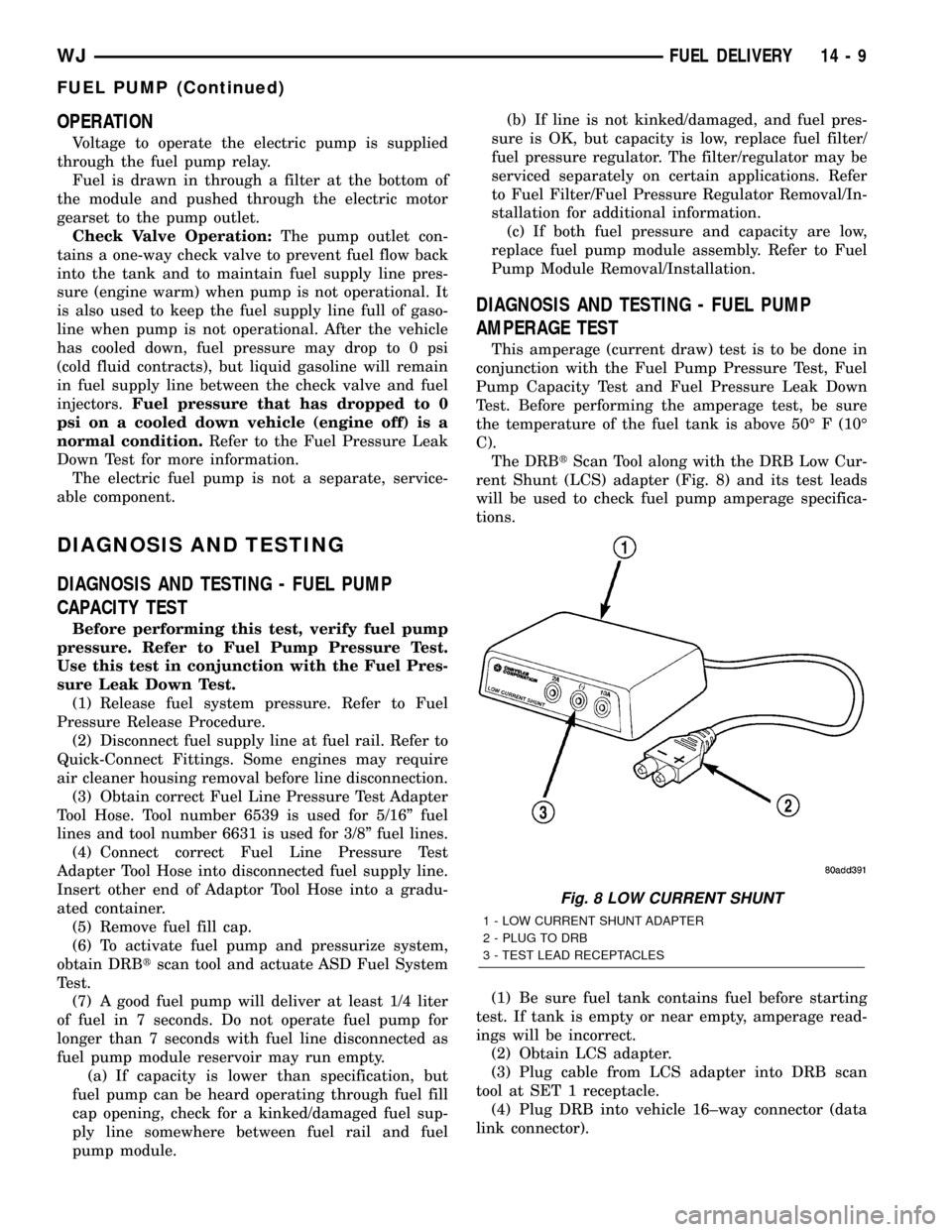
The DRBtScan Tool along with the DRB Low Cur-
rent Shunt (LCS) adapter (Fig. 8) and its test leads
will be used to check fuel pump amperage specifica-
tions.
(1) Be sure fuel tank contains fuel before starting
test. If tank is empty or near empty, amperage read-
ings will be incorrect.
(2) Obtain LCS adapter.
(3) Plug cable from LCS adapter into DRB scan
tool at SET 1 receptacle.
(4) Plug DRB into vehicle 16±way connector (data
link connector).
Fig. 8 LOW CURRENT SHUNT
1 - LOW CURRENT SHUNT ADAPTER
2 - PLUG TO DRB
3 - TEST LEAD RECEPTACLES
WJFUEL DELIVERY 14 - 9
FUEL PUMP (Continued)
Page 1430 of 2199
(19) Disconnect test leads from relay cavities
immediately after testing.
FUEL PUMP PRESSURE TEST
Use this test in conjunction with other fuel system
tests. Refer to the Fuel Pump Capacity Test, Fuel
Pressure Leak Down Test and Fuel Pump Amperage
Test.
Check Valve Operation:The electric fuel pump
outlet contains a one-way check valve to prevent fuel
flow back into the tank and to maintain fuel supply
line pressure (engine warm) when pump is not oper-
ational. It is also used to keep the fuel supply line
full of gasoline when pump is not operational. After
the vehicle has cooled down, fuel pressure may drop
to 0 psi (cold fluid contracts), but liquid gasoline will
remain in fuel supply line between the check valve
and fuel injectors.Fuel pressure that has
dropped to 0 psi on a cooled down vehicle
(engine off) is a normal condition.When the elec-
tric fuel pump is activated, fuel pressure should
immediately(1±2 seconds) rise to specification.
The fuel system is equipped with a combination
fuel filter/fuel pressure regulator. The fuel pressure
regulator is not controlled by engine vacuum.
WARNING: THE FUEL SYSTEM IS UNDER CON-
STANT FUEL PRESSURE EVEN WITH THE ENGINE
OFF. BEFORE DISCONNECTING FUEL LINE AT
FUEL RAIL, THIS PRESSURE MUST BE RELEASED.REFER TO THE FUEL SYSTEM PRESSURE
RELEASE PROCEDURE.
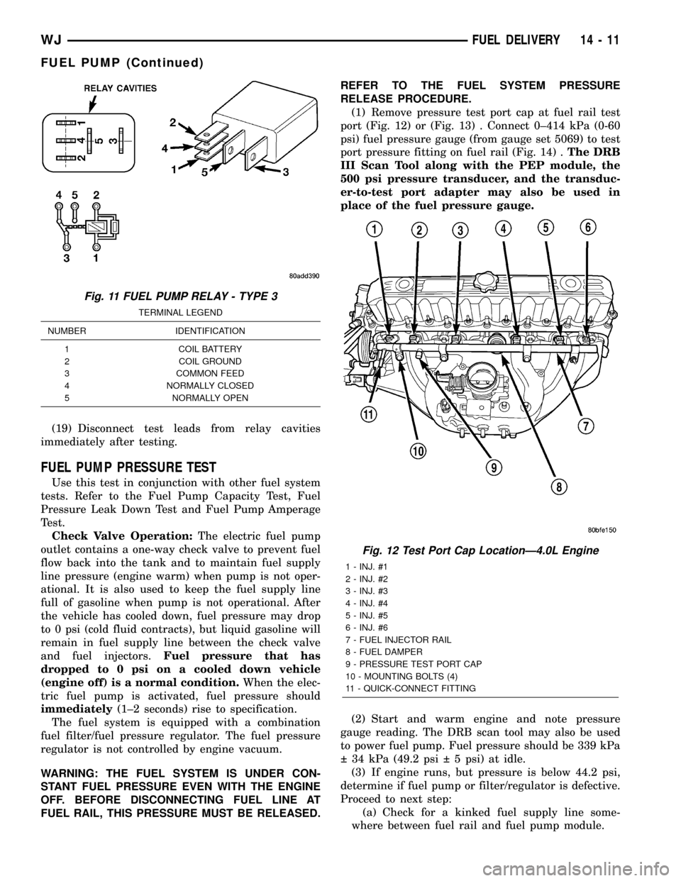
(1) Remove pressure test port cap at fuel rail test
port (Fig. 12) or (Fig. 13) . Connect 0±414 kPa (0-60
psi) fuel pressure gauge (from gauge set 5069) to test
port pressure fitting on fuel rail (Fig. 14) .The DRB
III Scan Tool along with the PEP module, the
500 psi pressure transducer, and the transduc-
er-to-test port adapter may also be used in
place of the fuel pressure gauge.
(2) Start and warm engine and note pressure
gauge reading. The DRB scan tool may also be used
to power fuel pump. Fuel pressure should be 339 kPa
34 kPa (49.2 psi 5 psi) at idle.
(3) If engine runs, but pressure is below 44.2 psi,
determine if fuel pump or filter/regulator is defective.
Proceed to next step:
(a) Check for a kinked fuel supply line some-
where between fuel rail and fuel pump module.
Fig. 11 FUEL PUMP RELAY - TYPE 3
TERMINAL LEGEND
NUMBER IDENTIFICATION
1 COIL BATTERY
2 COIL GROUND
3 COMMON FEED
4 NORMALLY CLOSED
5 NORMALLY OPEN
Fig. 12 Test Port Cap LocationÐ4.0L Engine
1 - INJ. #1
2 - INJ. #2
3 - INJ. #3
4 - INJ. #4
5 - INJ. #5
6 - INJ. #6
7 - FUEL INJECTOR RAIL
8 - FUEL DAMPER
9 - PRESSURE TEST PORT CAP
10 - MOUNTING BOLTS (4)
11 - QUICK-CONNECT FITTING
WJFUEL DELIVERY 14 - 11
FUEL PUMP (Continued)
Page 1462 of 2199

(5) Push sensor against flywheel/drive plate. With
sensor pushed against flywheel/drive plate, tighten
mounting bolt to 7 N´m (60 in. lbs.) torque.
(6) Route sensor wiring harness into wire shield.
(7) Connect sensor pigtail harness electrical con-
nector to main wiring harness.
INSTALLATION - 4.7L
(1) Clean out machined hole in engine block.
(2) Apply a small amount of engine oil to sensor
o-ring.
(3) Install sensor into engine block with a slight
rocking action. Do not twist sensor into position as
damage to o-ring may result.
CAUTION: Before tightening sensor mounting bolt,
be sure sensor is completely flush to cylinder
block. If sensor is not flush, damage to sensor
mounting tang may result.
(4) Install mounting bolt and tighten to 28 N´m
(21 ft. lbs.) torque.
(5) Connect electrical connector to sensor.
(6) Install starter motor. Refer to Starter Removal/
Installation.
FUEL INJECTOR
DESCRIPTION
A separate fuel injector (Fig. 24) is used for each
individual cylinder.
OPERATION
OPERATION
The fuel injectors are electrical solenoids. The
injector contains a pintle that closes off an orifice at
the nozzle end. When electric current is supplied to
the injector, the armature and needle move a short
distance against a spring, allowing fuel to flow out
the orifice. Because the fuel is under high pressure, a
fine spray is developed in the shape of a pencil
stream. The spraying action atomizes the fuel, add-
ing it to the air entering the combustion chamber.
The top (fuel entry) end of the injector (Fig. 24) is
attached into an opening on the fuel rail.
The nozzle (outlet) ends of the injectors are posi-
tioned into openings in the intake manifold just
above the intake valve ports of the cylinder head.
The engine wiring harness connector for each fuel
injector is equipped with an attached numerical tag
(INJ 1, INJ 2 etc.). This is used to identify each fuel
injector.
The injectors are electrically energized, individu-
ally and in a sequential order by the Powertrain Con-
trol Module (PCM). The PCM will adjust injector
pulse width by switching the ground path to each
individual injector on and off. Injector pulse width is
the period of time that the injector is energized. The
PCM will adjust injector pulse width based on vari-
ous inputs it receives.
Battery voltage is supplied to the injectors through
the ASD relay.
The PCM determines injector pulse width based on
various inputs.
OPERATION - PCM OUTPUT
The nozzle ends of the injectors are positioned into
openings in the intake manifold just above the intake
valve ports of the cylinder head. The engine wiring
harness connector for each fuel injector is equipped
with an attached numerical tag (INJ 1, INJ 2 etc.).
This is used to identify each fuel injector with its
respective cylinder number.
The injectors are energized individually in a
sequential order by the Powertrain Control Module
(PCM). The PCM will adjust injector pulse width by
switching the ground path to each individual injector
on and off. Injector pulse width is the period of time
that the injector is energized. The PCM will adjust
injector pulse width based on various inputs it
receives.
Battery voltage (12 volts +) is supplied to the injec-
tors through the ASD relay. The ASD relay will shut-
down the 12 volt power source to the fuel injectors if
the PCM senses the ignition is on, but the engine is
not running. This occurs after the engine has not
been running for approximately 1.8 seconds.
Fig. 24 Fuel InjectorÐ4.0L/4.7L Engines
1 - FUEL INJECTOR
2 - NOZZLE
3 - TOP (FUEL ENTRY)
WJFUEL INJECTION 14 - 43
CRANKSHAFT POSITION SENSOR (Continued)
Page 1508 of 2199
PUMP
TABLE OF CONTENTS
page page
PUMP
DESCRIPTION - 4.0L, 4.7L................32
OPERATION
OPERATION - 4.7L....................32
OPERATION - 4.0L....................32
DIAGNOSIS AND TESTING - PUMP LEAKAGE . 33
STANDARD PROCEDURE
STANDARD PROCEDURE - INITIAL
OPERATION - 4.0L....................33
STANDARD PROCEDURE - INITIAL
OPERATION - 4.7L....................33
REMOVAL
REMOVAL - 4.0L ENGINE...............34
REMOVAL - 4.7L ENGINE...............34
INSTALLATION
INSTALLATION - 4.0L ENGINE...........34
INSTALLATION - 4.7L ENGINE...........34
SPECIFICATIONS
TORQUE CHART......................35
SPECIAL TOOLS
POWER STEERING PUMP..............36
FLUID COOLER
DESCRIPTION.........................36
REMOVAL.............................36
INSTALLATION.........................37
HOSES - 4.0L
DESCRIPTION
DESCRIPTION - PRESSURE LINE........37
DESCRIPTION - RETURN LINE...........37
OPERATION
OPERATION - PRESSURE LINE..........37
OPERATION - RETURN LINE............37
REMOVAL.............................37
INSTALLATION.........................37
HOSES - 4.7L
DESCRIPTION
DESCRIPTION - 1/2º PRESSURE HOSE....38DESCRIPTION - 1/2º RETURN HOSE......38
DESCRIPTION - 3/8º PRESSURE HOSE....38
DESCRIPTION - 3/8º GEAR OUTLET HOSE . 38
DESCRIPTION - 3/8º RETURN HOSE......38
OPERATION
OPERATION - 1/2º PRESSURE HOSE......38
OPERATION - 1/2º RETURN HOSE........38
OPERATION - 3/8º PRESSURE HOSE......39
OPERATION - 3/8º GEAR OUTLET HOSE . . . 39
OPERATION - 3/8ºRETURN HOSE........39
REMOVAL
REMOVAL - 1/29PRESSURE HOSE.......39
REMOVAL - 1/29RETURN HOSE..........39
REMOVAL - 3/89PRESSURE HOSE.......39
REMOVAL - 3/89RETURN HOSE..........39
REMOVAL - 3/89GEAR OUTLET HOSE.....40
REMOVAL - INLET COOLER HOSE........40
REMOVAL - OUTLET COOLER HOSE......40
INSTALLATION
INSTALLATION - 1/29PRESSURE HOSE....40
INSTALLATION - 1/29RETURN HOSE......40
INSTALLATION - 3/89PRESSURE HOSE....41
INSTALLATION - 3/89RETURN HOSE......41
INSTALLATION - 3/89GEAR OUTLET HOSE . 41
INSTALLATION - INLET COOLER HOSE....41
INSTALLATION - OUTLET COOLER HOSE . . 41
PULLEY
DESCRIPTION
POWER STEERING PUMP PULLEY - 3.1L
DIESEL.............................41
REMOVAL.............................41
INSTALLATION.........................42
RESERVOIR
REMOVAL.............................42
INSTALLATION.........................42
WJPUMP 19 - 31
Page 1512 of 2199
SPECIFICATIONS
TORQUE CHART
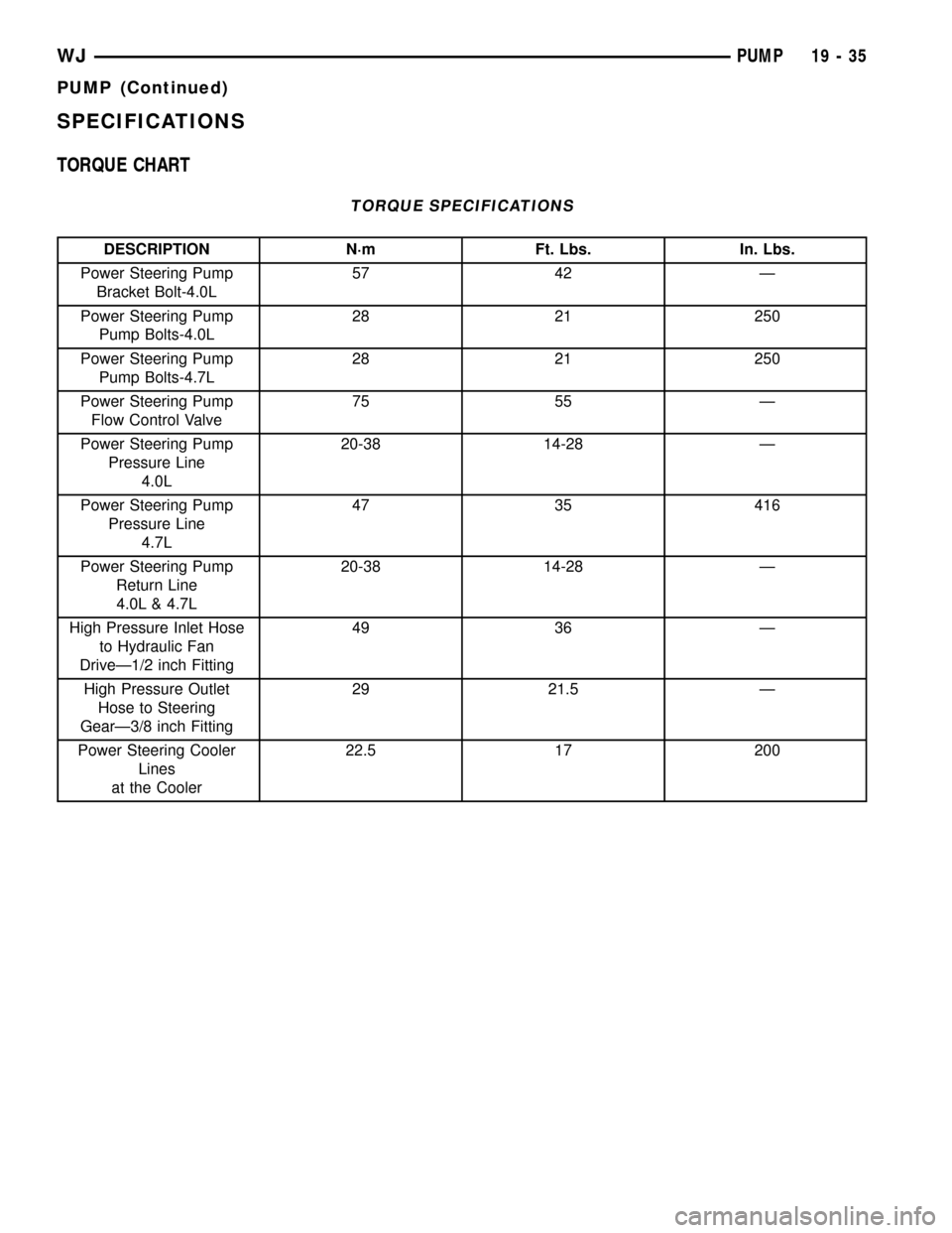
TORQUE SPECIFICATIONS
DESCRIPTION N´m Ft. Lbs. In. Lbs.
Power Steering Pump
Bracket Bolt-4.0L57 42 Ð
Power Steering Pump
Pump Bolts-4.0L28 21 250
Power Steering Pump
Pump Bolts-4.7L28 21 250
Power Steering Pump
Flow Control Valve75 55 Ð
Power Steering Pump
Pressure Line
4.0L20-38 14-28 Ð
Power Steering Pump
Pressure Line
4.7L47 35 416
Power Steering Pump
Return Line
4.0L & 4.7L20-38 14-28 Ð
High Pressure Inlet Hose
to Hydraulic Fan
DriveÐ1/2 inch Fitting49 36 Ð
High Pressure Outlet
Hose to Steering
GearÐ3/8 inch Fitting29 21.5 Ð
Power Steering Cooler
Lines
at the Cooler22.5 17 200
WJPUMP 19 - 35
PUMP (Continued)
Page 1515 of 2199
HOSES - 4.7L
DESCRIPTION
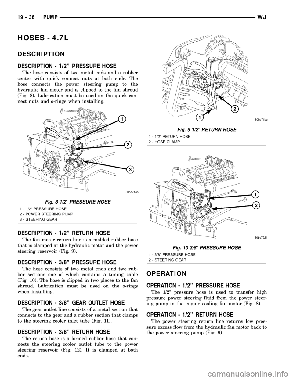
DESCRIPTION - 1/2º PRESSURE HOSE
The hose consists of two metal ends and a rubber
center with quick connect nuts at both ends. The
hose connects the power steering pump to the
hydraulic fan motor and is clipped to the fan shroud
(Fig. 8). Lubrication must be used on the quick con-
nect nuts and o-rings when installing.
DESCRIPTION - 1/2º RETURN HOSE
The fan motor return line is a molded rubber hose
that is clamped at the hydraulic motor and the power
steering reservoir (Fig. 9).
DESCRIPTION - 3/8º PRESSURE HOSE
The hose consists of two metal ends and two rub-
ber sections one of which contains a tuning cable
(Fig. 10). The hose is clipped in two places to the fan
shroud. Lubrication must be used on the o-rings
when installing.
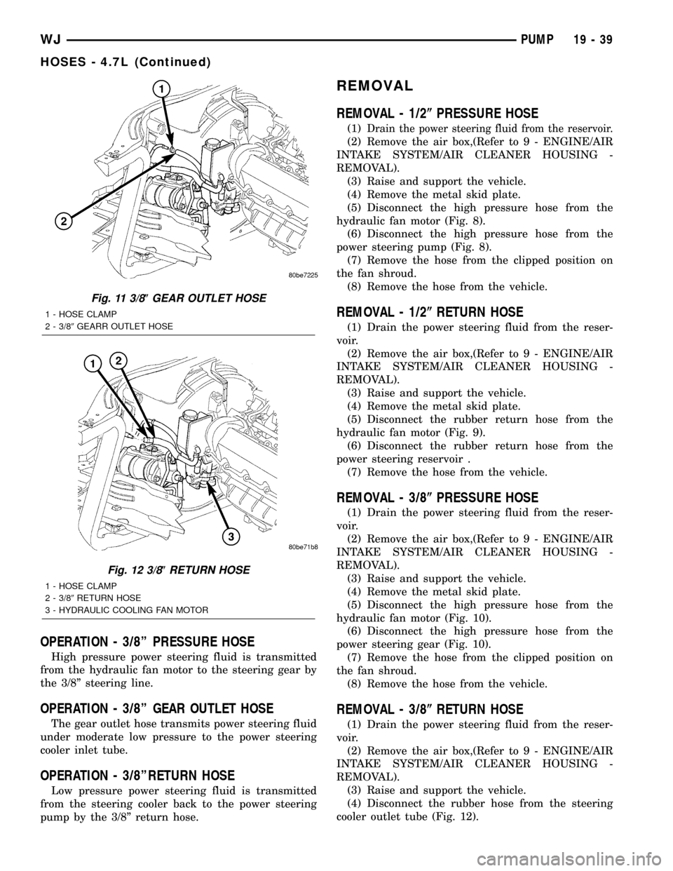
DESCRIPTION - 3/8º GEAR OUTLET HOSE
The gear outlet line consists of a metal section that
connects to the gear and a rubber section that clamps
to the steering cooler inlet tube (Fig. 11).
DESCRIPTION - 3/8º RETURN HOSE
The return hose is a formed rubber hose that con-
nects the steering cooler outlet tube to the power
steering reservoir (Fig. 12). It is clamped at both
ends.
OPERATION
OPERATION - 1/2º PRESSURE HOSE
The 1/2º pressure hose is used to transfer high
pressure power steering fluid from the power steer-
ing pump to the engine cooling fan motor (Fig. 8).
OPERATION - 1/2º RETURN HOSE
The power steering return line returns low pres-
sure excess flow from the hydraulic fan motor back to
the power steering pump (Fig. 9).
Fig. 8 1/2(PRESSURE HOSE
1 - 1/29PRESSURE HOSE
2 - POWER STEERING PUMP
3 - STEERING GEAR
Fig. 9 1/2(RETURN HOSE
1 - 1/29RETURN HOSE
2 - HOSE CLAMP
Fig. 10 3/8(PRESSURE HOSE
1 - 3/89PRESSURE HOSE
2 - STEERING GEAR
19 - 38 PUMPWJ
Page 1516 of 2199
OPERATION - 3/8º PRESSURE HOSE
High pressure power steering fluid is transmitted
from the hydraulic fan motor to the steering gear by
the 3/8º steering line.
OPERATION - 3/8º GEAR OUTLET HOSE
The gear outlet hose transmits power steering fluid
under moderate low pressure to the power steering
cooler inlet tube.
OPERATION - 3/8ºRETURN HOSE
Low pressure power steering fluid is transmitted
from the steering cooler back to the power steering
pump by the 3/8º return hose.
REMOVAL
REMOVAL - 1/2(PRESSURE HOSE
(1)Drain the power steering fluid from the reservoir.
(2) Remove the air box,(Refer to 9 - ENGINE/AIR
INTAKE SYSTEM/AIR CLEANER HOUSING -
REMOVAL).
(3) Raise and support the vehicle.
(4) Remove the metal skid plate.
(5) Disconnect the high pressure hose from the
hydraulic fan motor (Fig. 8).
(6) Disconnect the high pressure hose from the
power steering pump (Fig. 8).
(7) Remove the hose from the clipped position on
the fan shroud.
(8) Remove the hose from the vehicle.
REMOVAL - 1/2(RETURN HOSE
(1) Drain the power steering fluid from the reser-
voir.
(2) Remove the air box,(Refer to 9 - ENGINE/AIR
INTAKE SYSTEM/AIR CLEANER HOUSING -
REMOVAL).
(3) Raise and support the vehicle.
(4) Remove the metal skid plate.
(5) Disconnect the rubber return hose from the
hydraulic fan motor (Fig. 9).
(6) Disconnect the rubber return hose from the
power steering reservoir .
(7) Remove the hose from the vehicle.
REMOVAL - 3/8(PRESSURE HOSE
(1) Drain the power steering fluid from the reser-
voir.
(2) Remove the air box,(Refer to 9 - ENGINE/AIR
INTAKE SYSTEM/AIR CLEANER HOUSING -
REMOVAL).
(3) Raise and support the vehicle.
(4) Remove the metal skid plate.
(5) Disconnect the high pressure hose from the
hydraulic fan motor (Fig. 10).
(6) Disconnect the high pressure hose from the
power steering gear (Fig. 10).
(7) Remove the hose from the clipped position on
the fan shroud.
(8) Remove the hose from the vehicle.
REMOVAL - 3/8(RETURN HOSE
(1) Drain the power steering fluid from the reser-
voir.
(2) Remove the air box,(Refer to 9 - ENGINE/AIR
INTAKE SYSTEM/AIR CLEANER HOUSING -
REMOVAL).
(3) Raise and support the vehicle.
(4) Disconnect the rubber hose from the steering
cooler outlet tube (Fig. 12).
Fig. 11 3/8(GEAR OUTLET HOSE
1 - HOSE CLAMP
2 - 3/89GEARR OUTLET HOSE
Fig. 12 3/8(RETURN HOSE
1 - HOSE CLAMP
2 - 3/89RETURN HOSE
3 - HYDRAULIC COOLING FAN MOTOR
WJPUMP 19 - 39
HOSES - 4.7L (Continued)
Page 1517 of 2199
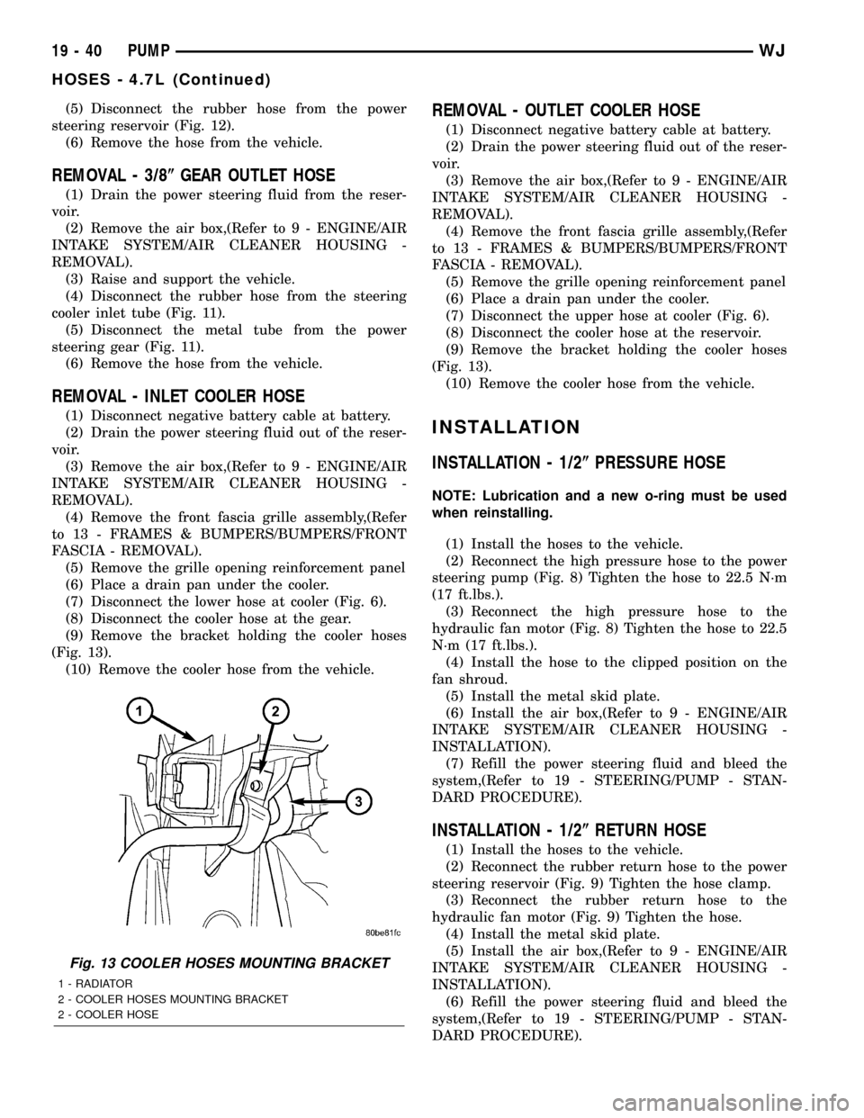
(5) Disconnect the rubber hose from the power
steering reservoir (Fig. 12).
(6) Remove the hose from the vehicle.
REMOVAL - 3/8(GEAR OUTLET HOSE
(1) Drain the power steering fluid from the reser-
voir.
(2) Remove the air box,(Refer to 9 - ENGINE/AIR
INTAKE SYSTEM/AIR CLEANER HOUSING -
REMOVAL).
(3) Raise and support the vehicle.
(4) Disconnect the rubber hose from the steering
cooler inlet tube (Fig. 11).
(5) Disconnect the metal tube from the power
steering gear (Fig. 11).
(6) Remove the hose from the vehicle.
REMOVAL - INLET COOLER HOSE
(1) Disconnect negative battery cable at battery.
(2) Drain the power steering fluid out of the reser-
voir.
(3) Remove the air box,(Refer to 9 - ENGINE/AIR
INTAKE SYSTEM/AIR CLEANER HOUSING -
REMOVAL).
(4) Remove the front fascia grille assembly,(Refer
to 13 - FRAMES & BUMPERS/BUMPERS/FRONT
FASCIA - REMOVAL).
(5) Remove the grille opening reinforcement panel
(6) Place a drain pan under the cooler.
(7) Disconnect the lower hose at cooler (Fig. 6).
(8) Disconnect the cooler hose at the gear.
(9) Remove the bracket holding the cooler hoses
(Fig. 13).
(10) Remove the cooler hose from the vehicle.
REMOVAL - OUTLET COOLER HOSE
(1) Disconnect negative battery cable at battery.
(2) Drain the power steering fluid out of the reser-
voir.
(3) Remove the air box,(Refer to 9 - ENGINE/AIR
INTAKE SYSTEM/AIR CLEANER HOUSING -
REMOVAL).
(4) Remove the front fascia grille assembly,(Refer
to 13 - FRAMES & BUMPERS/BUMPERS/FRONT
FASCIA - REMOVAL).
(5) Remove the grille opening reinforcement panel
(6) Place a drain pan under the cooler.
(7) Disconnect the upper hose at cooler (Fig. 6).
(8) Disconnect the cooler hose at the reservoir.
(9) Remove the bracket holding the cooler hoses
(Fig. 13).
(10) Remove the cooler hose from the vehicle.
INSTALLATION
INSTALLATION - 1/2(PRESSURE HOSE
NOTE: Lubrication and a new o-ring must be used
when reinstalling.
(1) Install the hoses to the vehicle.
(2) Reconnect the high pressure hose to the power
steering pump (Fig. 8) Tighten the hose to 22.5 N´m
(17 ft.lbs.).
(3) Reconnect the high pressure hose to the
hydraulic fan motor (Fig. 8) Tighten the hose to 22.5
N´m (17 ft.lbs.).
(4) Install the hose to the clipped position on the
fan shroud.
(5) Install the metal skid plate.
(6) Install the air box,(Refer to 9 - ENGINE/AIR
INTAKE SYSTEM/AIR CLEANER HOUSING -
INSTALLATION).
(7) Refill the power steering fluid and bleed the
system,(Refer to 19 - STEERING/PUMP - STAN-
DARD PROCEDURE).
INSTALLATION - 1/2(RETURN HOSE
(1) Install the hoses to the vehicle.
(2) Reconnect the rubber return hose to the power
steering reservoir (Fig. 9) Tighten the hose clamp.
(3) Reconnect the rubber return hose to the
hydraulic fan motor (Fig. 9) Tighten the hose.
(4) Install the metal skid plate.
(5) Install the air box,(Refer to 9 - ENGINE/AIR
INTAKE SYSTEM/AIR CLEANER HOUSING -
INSTALLATION).
(6) Refill the power steering fluid and bleed the
system,(Refer to 19 - STEERING/PUMP - STAN-
DARD PROCEDURE).
Fig. 13 COOLER HOSES MOUNTING BRACKET
1 - RADIATOR
2 - COOLER HOSES MOUNTING BRACKET
2 - COOLER HOSE
19 - 40 PUMPWJ
HOSES - 4.7L (Continued)