2002 JEEP GRAND CHEROKEE display
[x] Cancel search: displayPage 632 of 2199

switch mounting housing. Tighten the screws to 2.5
N´m (22 in. lbs.).
(3) Reconnect the instrument panel wire harness
connector for the right multi-function switch to the
switch connector receptacle.
(4) Position the lower tilting steering column
shroud to the underside of the steering column (Fig.
18).
(5) Install and tighten the screw that secures the
lower tilting steering column shroud to the multi-
function switch mounting housing. Tighten the screw
to 1.9 N´m (17 in. lbs.).
(6) Position the upper tilting column shroud over
the steering column with the hazard warning switch
button inserted through the hole in the upper surface
of the shroud. Align the upper tilting steering column
shroud to the lower shroud and snap the two shroud
halves together.
(7) Reconnect the battery negative cable.
WASHER FLUID LEVEL
SWITCH
DESCRIPTION
The washer fluid level switch is a single pole, sin-
gle throw reed-type switch mounted near the front of
the washer reservoir, forward of the two washer
pump/motors (Fig. 20). Only the molded plastic
switch mounting flange and connector receptacle are
visible when the switch is installed in the reservoir.A short nipple formation extends from the inner sur-
face of the switch mounting flange, and a barb on the
nipple near the switch mounting flange is press-fit
into a rubber grommet seal installed in the mounting
hole of the reservoir. A small plastic float pivots on
the end of a bracket that extends from the switch
nipple formation. Within the float is a small magnet,
which actuates the reed switch. The washer fluid
level switch cannot be adjusted or repaired. If faulty
or damaged, the switch must be replaced.
OPERATION
The washer fluid level switch uses a pivoting,
oblong float to monitor the level of the washer fluid
in the washer reservoir. The float contains a small
magnet. When the float pivots, the changing proxim-
ity of its magnetic field will cause the contacts of the
small, stationary reed switch to open or close. When
the fluid level in the washer reservoir is at or above
the float level, the float moves to a vertical position
and the switch contacts open. When the fluid level in
the washer reservoir falls below the pivoting float,
the float moves to a horizontal position and the
switch contacts close. The switch is connected to the
vehicle electrical system through a dedicated take
out and connector of the left headlamp and dash wire
harness. The switch receives a five volt reference sig-
nal from the Body Control Module (BCM) through
the washer fluid switch output circuit. The switch is
grounded at all times through another take out of
the left headlamp and dash wire harness with a sin-
gle eyelet terminal connector that is secured under a
ground screw near the top of the left front fender
inner shield in the engine compartment.
When the switch closes, the BCM senses the volt-
age change on the circuit. The BCM is programmed
to send low washer fluid messages to the Electronic
Vehicle Information Center (EVIC) over the Program-
mable Communications Interface (PCI) data bus. The
EVIC is programmed to respond to this message by
displaying the Washer Fluid Low warning and send-
ing a chime request message back to the BCM over
the PCI data bus. Then the BCM generates an audi-
ble chime tone warning. A resistor within the washer
fluid level switch allows the BCM to monitor and
diagnose this circuit. The BCM will store a Diagnos-
tic Trouble Code (DTC) for any fault that it detects.
For retrieval of this fault information and further
diagnosis of the washer fluid level switch, the BCM,
the EVIC, the PCI data bus, the BCM message out-
puts to the EVIC that control the Low Washer Fluid
indicator, or the EVIC message outputs to the BCM
that control chime service, a DRBIIItscan tool and
the appropriate diagnostic information are required.
Fig. 20 Washer Fluid Level Switch (Viewed from
Bottom of Reservoir)
1 - REAR WASHER PUMP/MOTOR
2 - FRONT WASHER PUMP/MOTOR
3 - WASHER FLUID LEVEL SWITCH
WJFRONT WIPERS/WASHERS 8R - 25
RIGHT MULTI-FUNCTION SWITCH (Continued)
Page 634 of 2199

WASHER RESERVOIR
DESCRIPTION
A single washer fluid reservoir is used for both the
front and rear washer systems (Fig. 22). The molded
plastic washer fluid reservoir is concealed between
the left front inner and outer fender panels, behind
the inner fender liner in front of the left front wheel.
The only visible component of the washer reservoir is
the filler neck and cap unit, which extends through a
hole in the left front wheel house extension panel
into the engine compartment. A bright yellow plastic
filler cap with a rubber seal and an International
Control and Display Symbol icon for ªWindshield
Washerº and the text ªWasher Fluid Onlyº molded
into it snaps over the open end of the filler neck. The
cap hinges on and is secured to a molded-in hook for-
mation on the rear of the reservoir filler neck.There are separate, dedicated holes on the out-
board side of the reservoir provided for the mounting
of the front and rear washer/pump motor units, and
another dedicated hole on the front of the reservoir
for the washer fluid level switch. The inboard side of
the washer reservoir has an integral flange that is
secured to the inside of the left front fender wheel
house by two screws, while an integral molded tab
engages a slot in the left front fender inner shield to
support the outboard side of the reservoir. Another
screw secures the reservoir filler neck to the left
front fender inner shield near the front of the engine
compartment. The left front fender wheel house
inner liner must be removed to access the washer
reservoir for service.
The washer reservoir cannot be repaired and, if
faulty or damaged, it must be replaced. The washer
reservoir, the grommet seals for the washer pump/
motor units and the washer fluid level switch, and
the filler cap are each available for service replace-
ment.
OPERATION
The washer fluid reservoir provides a secure,
on-vehicle storage location for a large reserve of
washer fluid for operation of the front and rear
washer systems. The washer reservoir filler neck pro-
vides a clearly marked and readily accessible point
from which to add washer fluid to the reservoir. The
front and rear washer/pump motor units are located
in a sump area near the front of the reservoir to be
certain that washer fluid will be available to the
pumps as the fluid level in the reservoir becomes
depleted. The front washer pump/motor unit is
mounted in the lowest position in the sump so that
the front washers will operate even after the rear
washer system will no longer operate. The washer
fluid level switch is mounted just above the sump
area of the reservoir so that there will be adequate
warning to the vehicle operator that the washer fluid
level is low, before the washer system will no longer
operate.
REMOVAL
(1) Disconnect and isolate the battery negative
cable.
(2) Remove the air cleaner housing from the top of
the left front fender wheel house. (Refer to 9 -
ENGINE/AIR INTAKE SYSTEM/AIR CLEANER
HOUSING - REMOVAL).
Fig. 22 Washer Reservoir
1 - LEFT FENDER INNER SHIELD
2 - SCREW (2)
3 - WASHER PUMP WIRE HARNESS CONNECTORS
4 - WASHER FLUID LEVEL SWITCH WIRE HARNESS
CONNECTOR
5 - WASHER RESERVOIR
WJFRONT WIPERS/WASHERS 8R - 27
Page 1871 of 2199
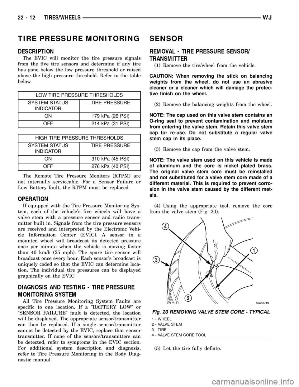
TIRE PRESSURE MONITORING
DESCRIPTION
The EVIC will monitor the tire pressure signals
from the five tire sensors and determine if any tire
has gone below the low pressure threshold or raised
above the high pressure threshold. Refer to the table
below.
LOW TIRE PRESSURE THRESHOLDS
SYSTEM STATUS
INDICATORTIRE PRESSURE
ON 179 kPa (26 PSI)
OFF 214 kPa (31 PSI)
HIGH TIRE PRESSURE THRESHOLDS
SYSTEM STATUS
INDICATORTIRE PRESSURE
ON 310 kPa (45 PSI)
OFF 276 kPa (40 PSI)
The Remote Tire Pressure Monitors (RTPM) are
not internally serviceable. For a Sensor Failure or
Low Battery fault, the RTPM must be replaced.
OPERATION
If equipped with the Tire Pressure Monitoring Sys-
tem, each of the vehicle's five wheels will have a
valve stem with a pressure sensor and radio trans-
mitter built in. Signals from the tire pressure sensors
are received and interpreted by the Electronic Vehi-
cle Information Center (EVIC). A sensor in a
mounted wheel will broadcast its detected pressure
once per minute when the vehicle is moving faster
than 40 km/h (25 mph). The spare tire sensor will
broadcast once every hour. Each sensor's broadcast is
uniquely coded so that the EVIC can determine loca-
tion. The individual tire pressures can be displayed
graphically on the EVIC
DIAGNOSIS AND TESTING - TIRE PRESSURE
MONITORING SYSTEM
All Tire Pressure Monitoring System Faults are
specific to one location. If a9BATTERY LOW9or
9SENSOR FAILURE9fault is detected, the location
will be displayed. The appropriate sensor/transmitter
can then be replaced. If a single sensor/transmitter
cannot be detected by the EVIC, replace that sensor
transmitter. If none of the sensors/transmitters can
be detected, refer to symptoms in the EVIC section.
For additional system description and diagnosis,
refer to Tire Pressure Monitoring in the Body Diag-
nostic manual.
SENSOR
REMOVAL - TIRE PRESSURE SENSOR/
TRANSMITTER
(1) Remove the tire/wheel from the vehicle.
CAUTION: When removing the stick on balancing
weights from the wheel, do not use an abrasive
cleaner or a cleaner which will damage the protec-
tive finish on the wheel.
(2) Remove the balancing weights from the wheel.
NOTE: The cap used on this valve stem contains an
O-ring seal to prevent contamination and moisture
from entering the valve stem. Retain this valve stem
cap for re-use. Do not substitute a regular valve
stem cap in its place.
(3) Remove the cap from the valve stem.
NOTE: The valve stem used on this vehicle is made
of aluminum and the core is nickel plated brass.
The original valve stem core must be reinstalled
and not substituted for a valve stem core made of a
different material. This is required to prevent corro-
sion in the valve stem caused by the different met-
als.
(4) Using the appropriate tool, remove the core
from the valve stem (Fig. 20).
(5) Let the tire fully deflate.
Fig. 20 REMOVING VALVE STEM CORE - TYPICAL
1 - WHEEL
2 - VALVE STEM
3 - TIRE
4 - VALVE STEM CORE TOOL
22 - 12 TIRES/WHEELSWJ
Page 2094 of 2199

open circuit to the fuse in the junction block as
required.
(5) The coil ground terminal cavity (85) is switched
to ground through the Powertrain Control Module
(PCM). There should be continuity between this cav-
ity and the A/C compressor clutch relay control cir-
cuit cavity of the PCM wire harness connector C
(gray) at all times. If not OK, repair the open circuit
as required.
REMOVAL
(1) Disconnect and isolate the battery negative
cable.
(2) Remove the cover from the Power Distribution
Center (PDC) (Fig. 11).
(3) Refer to the label on the PDC for compressor
clutch relay identification and location.
(4) Unplug the compressor clutch relay from the
PDC.
INSTALLATION
(1) Install the compressor clutch relay by aligning
the relay terminals with the cavities in the PDC and
pushing the relay firmly into place.
(2) Install the PDC cover.
(3) Connect the battery negative cable.
(4) Test the relay operation.
A/C HEATER CONTROL
DESCRIPTION
The manual temperature control HVAC system
uses a combination of electrical, and vacuum con-trols. The Automatic Zone Control (AZC) HVAC sys-
tem uses only electrical controls. These controls
provide the vehicle operator with a number of setting
options to help control the climate and comfort
within the vehicle. Refer to the owner's manual in
the vehicle glove box for more information on the
suggested operation and use of these controls.
Both a/c heater control panels are located on the
instrument panel inboard of the steering column and
below the radio (Fig. 12). Both control panels contain
rotary-type temperature control knob(s), a rotary-
type mode control switch knob, a rotary-type blower
motor speed switch knob and an air conditioning
compressor push button switch. The rear window
defogger push button switch is also located on a/c
heater control panel. The AZC control panel also fea-
tures a recirculation push button switch and a vac-
uum fluorescent display area.
OPERATION
The AZC control module uses infrared sensing
technology to control occupant comfort levels, not the
actual passenger compartment air temperature. Dual
infrared sensors mounted in the face of the control
unit independently measure the surface temperature
to maintain customer-perceived comfort temperature
under changing conditions. Dual Zone temperature
control provides wide side-to-side variation in comfort
temperature to exceed the needs of either front seat
occupant. This sensing system replaces interior air
temperature and solar sensors used to approximate
direct sensing control through complex control pro-
grams.
Fig. 11 POWER DISTRIBUTION CENTER (PDC)
1 - TRANSMISSION CONTROL MODULE (TCM)
2 - NEGATIVE CABLE
3 - POSITIVE CABLE
4 - POWER DISTRIBUTION CENTER (PDC)
Fig. 12 A/C HEATER CONTROL PANELS
WJCONTROLS 24 - 17
A/C COMPRESSOR CLUTCH RELAY (Continued)
Page 2095 of 2199
Both the manual A/C Heater control panel and the
AZC control panel are serviced only as complete
units and cannot be repaired. If faulty or damaged,
the entire control panel unit must be replaced.
DIAGNOSIS AND TESTING - AUTOMATIC ZONE
CONTROL SYSTEM
The Automatic Zone Control (AZC) control module
has a system self-diagnostic mode which continuously
monitors various parameters during normal system
operation. If a system fault is detected, a current and
historical fault is recorded. When the current fault is
cleared, the historical fault remains until reset (man-
ually or automatically). Both the current and histor-
ical fault codes can be accessed through either the
front panel, or over the Programmable Communica-
tions Interface (PCI) bus using a DRBIIItscan tool,
and the appropriate diagnostic information.
The AZC control module is capable of three differ-
ent types of self-diagnostic tests, as follows:
²Fault Code Tests
²Input Circuit Tests
²Output Circuit/Actuator Tests
The information that follows describes:
²How to read the self-diagnostic display
²How to enter the AZC control module self-diag-
nostic test mode
²How to select the self-diagnostic test types
²How to perform the different tests
ENTERING THE AZC SELF-DIAGNOSTIC MODE
To enter the AZC self-diagnostic mode, perform the
following:
(1) Depress the a/c and recirc buttons at the same
time and hold. Rotate the left temperature control
knob clockwise (CW) one detent.
(2) If you continue to keep the a/c and recirc but-
tons depressed, the AZC control module will perform
a Segment Test of the Vacuum Fluorescent (VF) dis-
play. In the Segment Test you should see all of the
display segments illuminate as long as both buttons
are held. If a display segment fails to illuminate, the
vacuum fluorescent display is faulty and the a/c
heater control must be replaced.
(3) After viewing the Segment Test, release the
A/C and Recirc buttons and the display will clear
momentarily.Ifa0isdisplayed, then no faults
are set in the system.Should there be any faults,
either9current9or9historical9, all fault codes will be
displayed in ascending numerical sequence (note no
effort is made to display fault codes in chronological
order). Each fault code is displayed for one second
before the next code is displayed. Once all fault codes
have been displayed, the system will then repeat the
fault code numbers. This will continue until the left
side set temperature control is moved at least onedetent position in the CW direction or the ignition is
turned9OFF9.
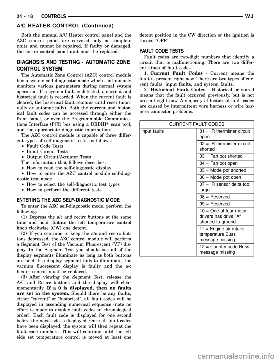
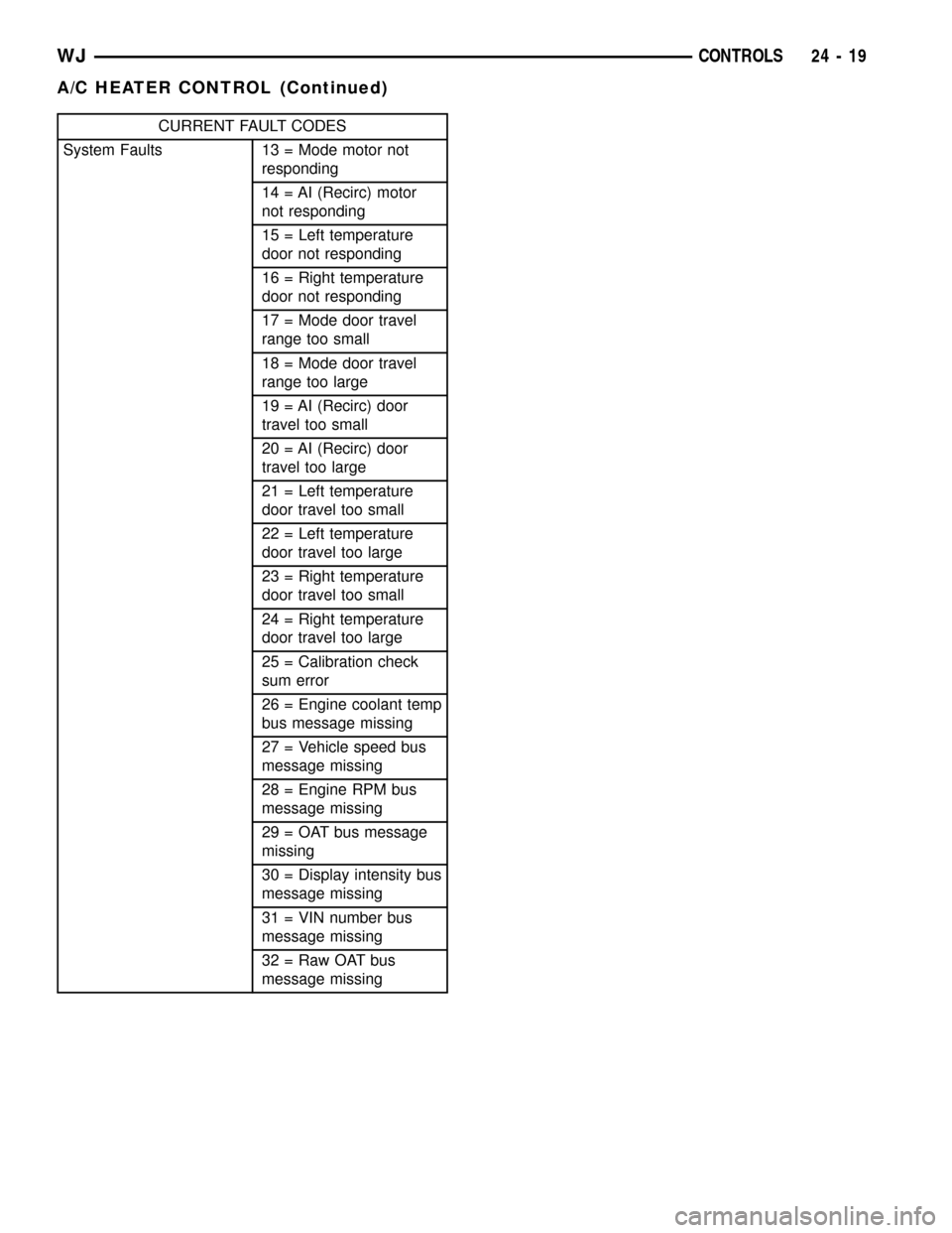
FAULT CODE TESTS
Fault codes are two-digit numbers that identify a
circuit that is malfunctioning. There are two differ-
ent kinds of fault codes.
1.Current Fault Codes- Current means the
fault is present right now. There are two types of cur-
rent faults: input faults, and system faults.
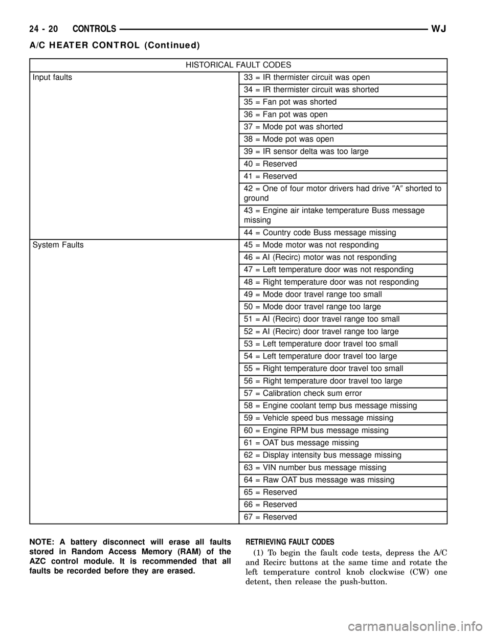
2.Historical Fault Codes- Historical or stored
means that the fault occurred previously, but is not
present right now. A majority of historical fault codes
are caused by intermittent wire harness or wire har-
ness connector problems.
CURRENT FAULT CODES
Input faults 01 = IR thermister circuit
open
02 = IR thermister circuit
shorted
03 = Fan pot shorted
04 = Fan pot open
05 = Mode pot shorted
06 = Mode pot open
07 = IR sensor delta too
large
08 = Reserved
09 = Reserved
10 = One of four motor
drivers has drive9A9
shorted to ground
11 = Engine air intake
temperature Buss
message missing
12 = Country code Buss
message missing
24 - 18 CONTROLSWJ
A/C HEATER CONTROL (Continued)
Page 2096 of 2199
CURRENT FAULT CODES
System Faults 13 = Mode motor not
responding
14 = AI (Recirc) motor
not responding
15 = Left temperature
door not responding
16 = Right temperature
door not responding
17 = Mode door travel
range too small
18 = Mode door travel
range too large
19 = AI (Recirc) door
travel too small
20 = AI (Recirc) door
travel too large
21 = Left temperature
door travel too small
22 = Left temperature
door travel too large
23 = Right temperature
door travel too small
24 = Right temperature
door travel too large
25 = Calibration check
sum error
26 = Engine coolant temp
bus message missing
27 = Vehicle speed bus
message missing
28 = Engine RPM bus
message missing
29 = OAT bus message
missing
30 = Display intensity bus
message missing
31 = VIN number bus
message missing
32 = Raw OAT bus
message missing
WJCONTROLS 24 - 19
A/C HEATER CONTROL (Continued)
Page 2097 of 2199
HISTORICAL FAULT CODES
Input faults 33 = IR thermister circuit was open
34 = IR thermister circuit was shorted
35 = Fan pot was shorted
36 = Fan pot was open
37 = Mode pot was shorted
38 = Mode pot was open
39 = IR sensor delta was too large
40 = Reserved
41 = Reserved
42 = One of four motor drivers had drive9A9shorted to
ground
43 = Engine air intake temperature Buss message
missing
44 = Country code Buss message missing
System Faults 45 = Mode motor was not responding
46 = AI (Recirc) motor was not responding
47 = Left temperature door was not responding
48 = Right temperature door was not responding
49 = Mode door travel range too small
50 = Mode door travel range too large
51 = AI (Recirc) door travel range too small
52 = AI (Recirc) door travel range too large
53 = Left temperature door travel too small
54 = Left temperature door travel too large
55 = Right temperature door travel too small
56 = Right temperature door travel too large
57 = Calibration check sum error
58 = Engine coolant temp bus message missing
59 = Vehicle speed bus message missing
60 = Engine RPM bus message missing
61 = OAT bus message missing
62 = Display intensity bus message missing
63 = VIN number bus message missing
64 = Raw OAT bus message was missing
65 = Reserved
66 = Reserved
67 = Reserved
NOTE: A battery disconnect will erase all faults
stored in Random Access Memory (RAM) of the
AZC control module. It is recommended that all
faults be recorded before they are erased.RETRIEVING FAULT CODES
(1) To begin the fault code tests, depress the A/C
and Recirc buttons at the same time and rotate the
left temperature control knob clockwise (CW) one
detent, then release the push-button.
24 - 20 CONTROLSWJ
A/C HEATER CONTROL (Continued)
Page 2098 of 2199
(2)If there are no fault codes, the ª00º dis-
play value will remain in the VF window.Should
there be any codes, each will be displayed for one
second in ascending numerical sequence (note: no
effort is made to display faults in the order they
occurred). The left side set temperature display will
be blanked and the right side set temperature dis-
play will indicate current and historical codes (8 his-
torical max) presently active. Once all codes have
been displayed, the system will repeat the fault code
numbers. This will continue until the left side set
temperature control is moved at least one detent
position in either direction, by pressing both the A/C
and Recirc buttons at the same time, or the ignition
is turned off. Record all of the fault codes, then see
the Current and Historical Fault Code charts for the
descriptions.
CLEARING FAULT CODES
Current faults cannot be electronically cleared.
Repair must be made to the system to eliminate the
fault causing code. Historical fault codes can be
cleared manually, or automatically. To clear a histor-
ical fault manually, depress and hold either the A/C
or Recirc button for at least three seconds while the
display is in the fault code mode of operation. Histor-
ical fault codes are cleared automatically when the
corresponding current fault code has been cleared,
and has remained cleared for a number of ignition
cycles. The faults have been cleared when two hori-
zontal bars appear in the Test Selector display.
EXITING SELF-DIAGNOSTIC MODE
The self-diagnostic mode can be exited by pressing
both the A/C and Recirc buttons at the same time, or
turning off the ignition.
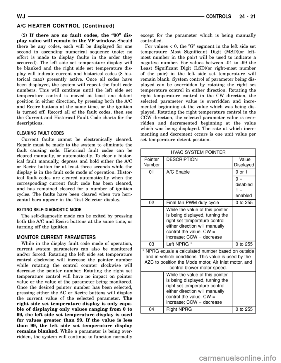
MONITOR CURRENT PARAMETERS
While in the display fault code mode of operation,
current system parameters can also be monitored
and/or forced. Rotating the left side set temperature
control clockwise will increase the pointer number
while rotating the control counter clockwise will
decrease the pointer number. Rotating the right set
temperature control will have no impact on pointer
value or the value of the parameter being monitored.
Once the desired pointer number has been selected,
pressing either the AC or Recirc buttons will display
the current value of the selected parameter.The
right side set temperature display is only capa-
ble of displaying only values ranging from 0 to
99, the left side set temperature display is used
for values greater than 99. If the value is less
than 99, the left side set temperature display
remains blanked.While a parameter is being over-
ridden, the system will continue to function normallyexcept for the parameter which is being manually
controlled.
For values < 0, the9G9segment in the left side set
temperature Most Significant Digit (MSD)(or left-
most number in the pair) will be used to indicate a
negative number. For values between -01 to -99 the
Least Significant Digit (LSD)(or right-most number
of the pair) in the left side set temperature will
remain blank. System control of parameter being dis-
played can be overridden by rotating the right set
temperature control in either direction. Rotating the
right temperature control in the CW direction, the
selected parameter value is overridden and incre-
mented beginning at the value which was being dis-
played. Rotating the right temperature control in the
CCW direction, the selected parameter value is over-
ridden and decremented beginning at the value
which was being displayed. The rate at which incre-
menting and decrement occurs is one unit value per
set temperature detent position.
HVAC SYSTEM POINTER
Pointer
NumberDESCRIPTION Value
Displayed
01 A/C Enable 0 or 1
0=
disabled
1=
enabled
02 Final fan PWM duty cycle 0 to 255
While the value of this pointer
is being displayed, turning the
right set temperature control
either direction will manually
control the value. CW =
increase; CCW = decrease
03 Left NPRG * 0 to 255
* NPRG equals a calculated number based on outside
and in-vehicle conditions. This value is used by the
AZC to position the Mode motor, Air Inlet motor, and
control blower motor speed.
While the value of this pointer
is being displayed, turning the
right set temperature control
either direction will manually
control the value. CW =
increase; CCW = decrease
04 Right NPRG 0 to 255
WJCONTROLS 24 - 21
A/C HEATER CONTROL (Continued)