2002 JEEP GRAND CHEROKEE clutch
[x] Cancel search: clutchPage 1053 of 2199
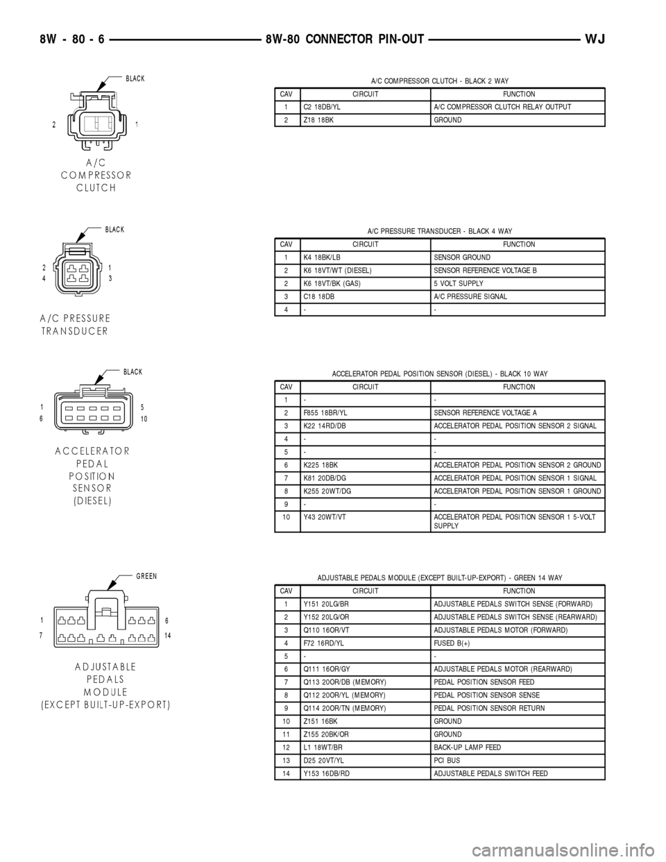
A/C COMPRESSOR CLUTCH - BLACK 2 WAY
CAV CIRCUIT FUNCTION
1 C2 18DB/YL A/C COMPRESSOR CLUTCH RELAY OUTPUT
2 Z18 18BK GROUND
A/C PRESSURE TRANSDUCER - BLACK 4 WAY
CAV CIRCUIT FUNCTION
1 K4 18BK/LB SENSOR GROUND
2 K6 18VT/WT (DIESEL) SENSOR REFERENCE VOLTAGE B
2 K6 18VT/BK (GAS) 5 VOLT SUPPLY
3 C18 18DB A/C PRESSURE SIGNAL
4- -
ACCELERATOR PEDAL POSITION SENSOR (DIESEL) - BLACK 10 WAY
CAV CIRCUIT FUNCTION
1- -
2 F855 18BR/YL SENSOR REFERENCE VOLTAGE A
3 K22 14RD/DB ACCELERATOR PEDAL POSITION SENSOR 2 SIGNAL
4- -
5- -
6 K225 18BK ACCELERATOR PEDAL POSITION SENSOR 2 GROUND
7 K81 20DB/DG ACCELERATOR PEDAL POSITION SENSOR 1 SIGNAL
8 K255 20WT/DG ACCELERATOR PEDAL POSITION SENSOR 1 GROUND
9- -
10 Y43 20WT/VT ACCELERATOR PEDAL POSITION SENSOR 1 5-VOLT
SUPPLY
ADJUSTABLE PEDALS MODULE (EXCEPT BUILT-UP-EXPORT) - GREEN 14 WAY
CAV CIRCUIT FUNCTION
1 Y151 20LG/BR ADJUSTABLE PEDALS SWITCH SENSE (FORWARD)
2 Y152 20LG/OR ADJUSTABLE PEDALS SWITCH SENSE (REARWARD)
3 Q110 16OR/VT ADJUSTABLE PEDALS MOTOR (FORWARD)
4 F72 16RD/YL FUSED B(+)
5- -
6 Q111 16OR/GY ADJUSTABLE PEDALS MOTOR (REARWARD)
7 Q113 20OR/DB (MEMORY) PEDAL POSITION SENSOR FEED
8 Q112 20OR/YL (MEMORY) PEDAL POSITION SENSOR SENSE
9 Q114 20OR/TN (MEMORY) PEDAL POSITION SENSOR RETURN
10 Z151 16BK GROUND
11 Z155 20BK/OR GROUND
12 L1 18WT/BR BACK-UP LAMP FEED
13 D25 20VT/YL PCI BUS
14 Y153 16DB/RD ADJUSTABLE PEDALS SWITCH FEED
8W - 80 - 6 8W-80 CONNECTOR PIN-OUTWJ
Page 1123 of 2199
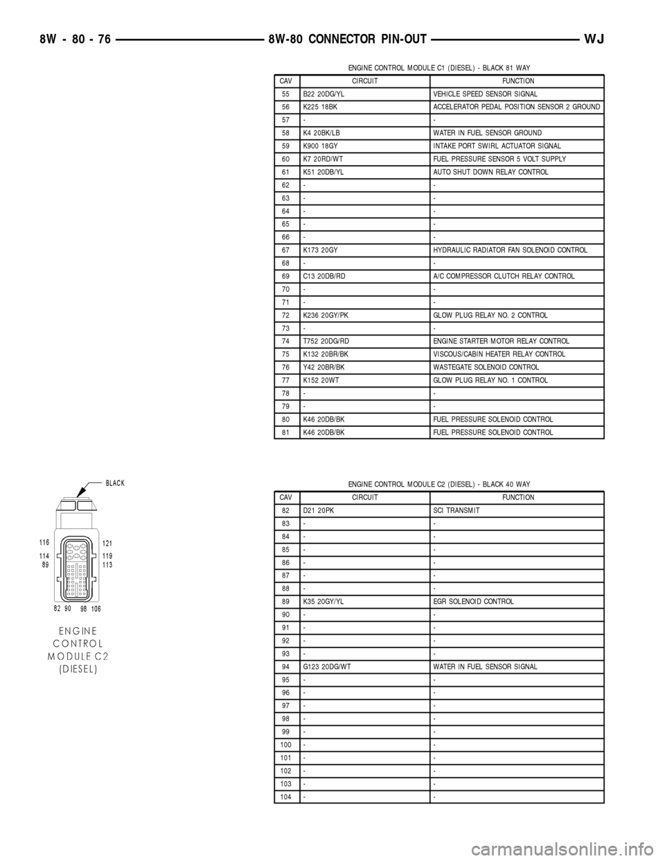
ENGINE CONTROL MODULE C1 (DIESEL) - BLACK 81 WAY
CAV CIRCUIT FUNCTION
55 B22 20DG/YL VEHICLE SPEED SENSOR SIGNAL
56 K225 18BK ACCELERATOR PEDAL POSITION SENSOR 2 GROUND
57 - -
58 K4 20BK/LB WATER IN FUEL SENSOR GROUND
59 K900 18GY INTAKE PORT SWIRL ACTUATOR SIGNAL
60 K7 20RD/WT FUEL PRESSURE SENSOR 5 VOLT SUPPLY
61 K51 20DB/YL AUTO SHUT DOWN RELAY CONTROL
62 - -
63 - -
64 - -
65 - -
66 - -
67 K173 20GY HYDRAULIC RADIATOR FAN SOLENOID CONTROL
68 - -
69 C13 20DB/RD A/C COMPRESSOR CLUTCH RELAY CONTROL
70 - -
71 - -
72 K236 20GY/PK GLOW PLUG RELAY NO. 2 CONTROL
73 - -
74 T752 20DG/RD ENGINE STARTER MOTOR RELAY CONTROL
75 K132 20BR/BK VISCOUS/CABIN HEATER RELAY CONTROL
76 Y42 20BR/BK WASTEGATE SOLENOID CONTROL
77 K152 20WT GLOW PLUG RELAY NO. 1 CONTROL
78 - -
79 - -
80 K46 20DB/BK FUEL PRESSURE SOLENOID CONTROL
81 K46 20DB/BK FUEL PRESSURE SOLENOID CONTROL
ENGINE CONTROL MODULE C2 (DIESEL) - BLACK 40 WAY
CAV CIRCUIT FUNCTION
82 D21 20PK SCI TRANSMIT
83 - -
84 - -
85 - -
86 - -
87 - -
88 - -
89 K35 20GY/YL EGR SOLENOID CONTROL
90 - -
91 - -
92 - -
93 - -
94 G123 20DG/WT WATER IN FUEL SENSOR SIGNAL
95 - -
96 - -
97 - -
98 - -
99 - -
100 - -
101 - -
102 - -
103 - -
104 - -
8W - 80 - 76 8W-80 CONNECTOR PIN-OUTWJ
Page 1156 of 2199
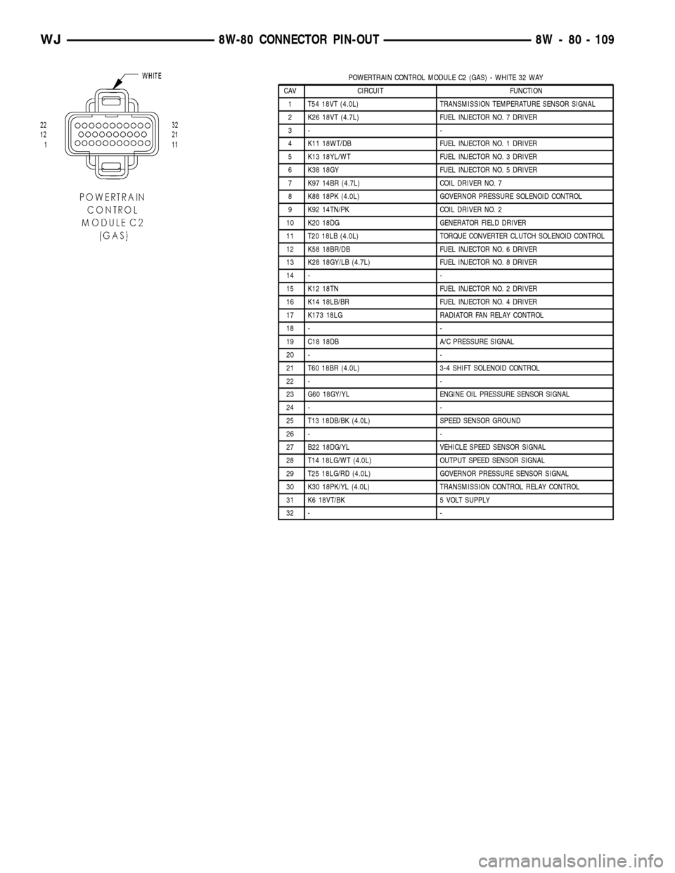
POWERTRAIN CONTROL MODULE C2 (GAS) - WHITE 32 WAY
CAV CIRCUIT FUNCTION
1 T54 18VT (4.0L) TRANSMISSION TEMPERATURE SENSOR SIGNAL
2 K26 18VT (4.7L) FUEL INJECTOR NO. 7 DRIVER
3- -
4 K11 18WT/DB FUEL INJECTOR NO. 1 DRIVER
5 K13 18YL/WT FUEL INJECTOR NO. 3 DRIVER
6 K38 18GY FUEL INJECTOR NO. 5 DRIVER
7 K97 14BR (4.7L) COIL DRIVER NO. 7
8 K88 18PK (4.0L) GOVERNOR PRESSURE SOLENOID CONTROL
9 K92 14TN/PK COIL DRIVER NO. 2
10 K20 18DG GENERATOR FIELD DRIVER
11 T20 18LB (4.0L) TORQUE CONVERTER CLUTCH SOLENOID CONTROL
12 K58 18BR/DB FUEL INJECTOR NO. 6 DRIVER
13 K28 18GY/LB (4.7L) FUEL INJECTOR NO. 8 DRIVER
14 - -
15 K12 18TN FUEL INJECTOR NO. 2 DRIVER
16 K14 18LB/BR FUEL INJECTOR NO. 4 DRIVER
17 K173 18LG RADIATOR FAN RELAY CONTROL
18 - -
19 C18 18DB A/C PRESSURE SIGNAL
20 - -
21 T60 18BR (4.0L) 3-4 SHIFT SOLENOID CONTROL
22 - -
23 G60 18GY/YL ENGINE OIL PRESSURE SENSOR SIGNAL
24 - -
25 T13 18DB/BK (4.0L) SPEED SENSOR GROUND
26 - -
27 B22 18DG/YL VEHICLE SPEED SENSOR SIGNAL
28 T14 18LG/WT (4.0L) OUTPUT SPEED SENSOR SIGNAL
29 T25 18LG/RD (4.0L) GOVERNOR PRESSURE SENSOR SIGNAL
30 K30 18PK/YL (4.0L) TRANSMISSION CONTROL RELAY CONTROL
31 K6 18VT/BK 5 VOLT SUPPLY
32 - -
WJ8W-80 CONNECTOR PIN-OUT 8W - 80 - 109
Page 1157 of 2199
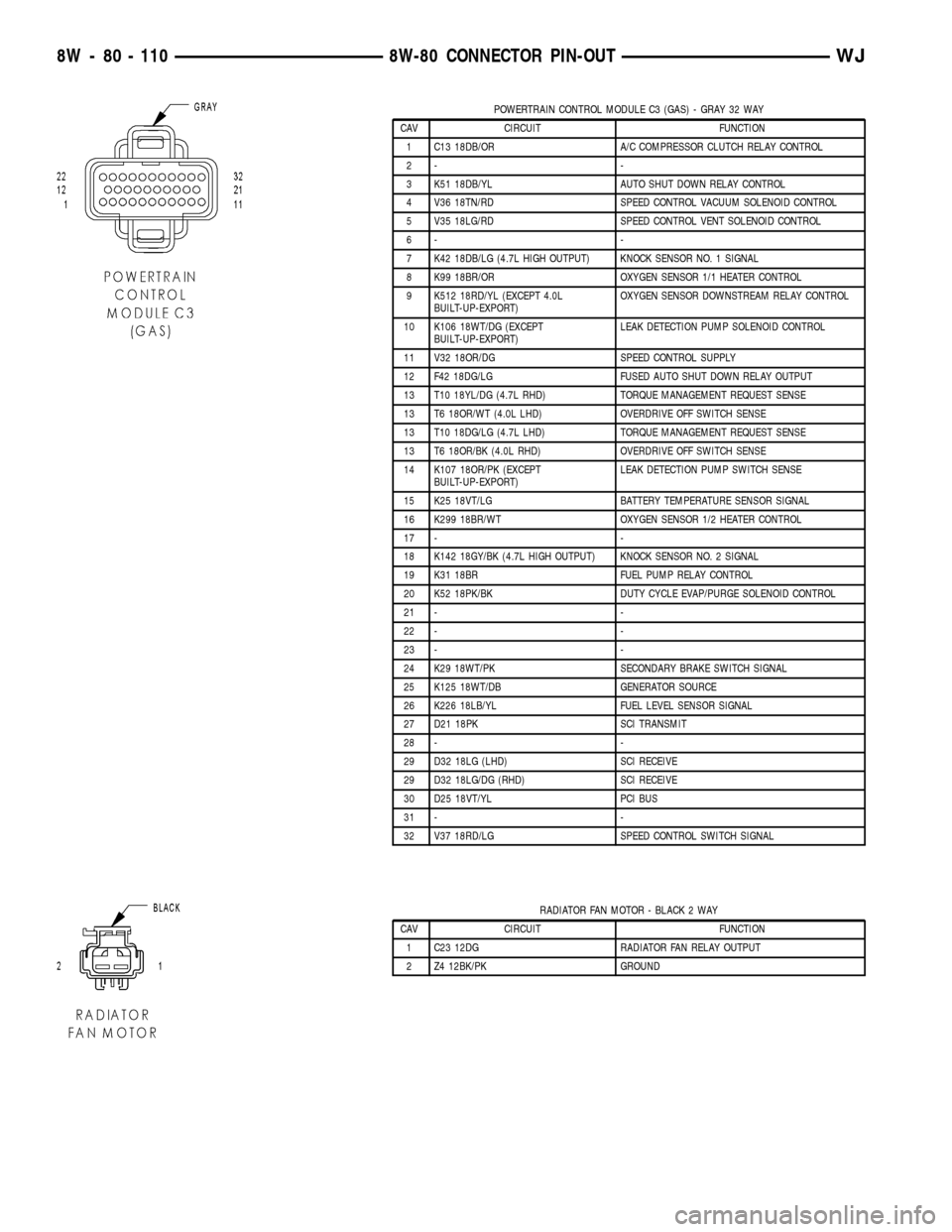
POWERTRAIN CONTROL MODULE C3 (GAS) - GRAY 32 WAY
CAV CIRCUIT FUNCTION
1 C13 18DB/OR A/C COMPRESSOR CLUTCH RELAY CONTROL
2- -
3 K51 18DB/YL AUTO SHUT DOWN RELAY CONTROL
4 V36 18TN/RD SPEED CONTROL VACUUM SOLENOID CONTROL
5 V35 18LG/RD SPEED CONTROL VENT SOLENOID CONTROL
6- -
7 K42 18DB/LG (4.7L HIGH OUTPUT) KNOCK SENSOR NO. 1 SIGNAL
8 K99 18BR/OR OXYGEN SENSOR 1/1 HEATER CONTROL
9 K512 18RD/YL (EXCEPT 4.0L
BUILT-UP-EXPORT)OXYGEN SENSOR DOWNSTREAM RELAY CONTROL
10 K106 18WT/DG (EXCEPT
BUILT-UP-EXPORT)LEAK DETECTION PUMP SOLENOID CONTROL
11 V32 18OR/DG SPEED CONTROL SUPPLY
12 F42 18DG/LG FUSED AUTO SHUT DOWN RELAY OUTPUT
13 T10 18YL/DG (4.7L RHD) TORQUE MANAGEMENT REQUEST SENSE
13 T6 18OR/WT (4.0L LHD) OVERDRIVE OFF SWITCH SENSE
13 T10 18DG/LG (4.7L LHD) TORQUE MANAGEMENT REQUEST SENSE
13 T6 18OR/BK (4.0L RHD) OVERDRIVE OFF SWITCH SENSE
14 K107 18OR/PK (EXCEPT
BUILT-UP-EXPORT)LEAK DETECTION PUMP SWITCH SENSE
15 K25 18VT/LG BATTERY TEMPERATURE SENSOR SIGNAL
16 K299 18BR/WT OXYGEN SENSOR 1/2 HEATER CONTROL
17 - -
18 K142 18GY/BK (4.7L HIGH OUTPUT) KNOCK SENSOR NO. 2 SIGNAL
19 K31 18BR FUEL PUMP RELAY CONTROL
20 K52 18PK/BK DUTY CYCLE EVAP/PURGE SOLENOID CONTROL
21 - -
22 - -
23 - -
24 K29 18WT/PK SECONDARY BRAKE SWITCH SIGNAL
25 K125 18WT/DB GENERATOR SOURCE
26 K226 18LB/YL FUEL LEVEL SENSOR SIGNAL
27 D21 18PK SCI TRANSMIT
28 - -
29 D32 18LG (LHD) SCI RECEIVE
29 D32 18LG/DG (RHD) SCI RECEIVE
30 D25 18VT/YL PCI BUS
31 - -
32 V37 18RD/LG SPEED CONTROL SWITCH SIGNAL
RADIATOR FAN MOTOR - BLACK 2 WAY
CAV CIRCUIT FUNCTION
1 C23 12DG RADIATOR FAN RELAY OUTPUT
2 Z4 12BK/PK GROUND
8W - 80 - 110 8W-80 CONNECTOR PIN-OUTWJ
Page 1172 of 2199
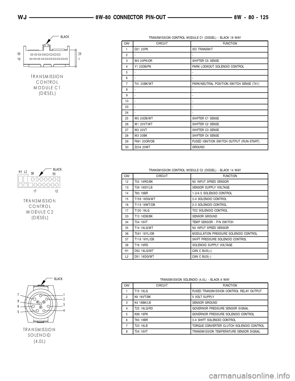
TRANSMISSION CONTROL MODULE C1 (DIESEL) - BLACK 18 WAY
CAV CIRCUIT FUNCTION
1 D21 20PK SCI TRANSMIT
2- -
3 W4 20PK/OR SHIFTER C5 SENSE
4 Y1 20DB/PK PARK LOCKOUT SOLENOID CONTROL
5- -
6- -
7 T41 20BK/WT PARK/NEUTRAL POSITION SWITCH SENSE (T41)
8- -
9- -
10 - -
23 - -
24 - -
25 W0 20DB/WT SHIFTER C1 SENSE
26 W1 20VT/WT SHIFTER C2 SENSE
27 W2 20VT SHIFTER C3 SENSE
28 W3 20BK SHIFTER C4 SENSE
29 F991 20OR/DB FUSED IGNITION SWITCH OUTPUT (RUN-START)
30 Z234 20WT GROUND
TRANSMISSION CONTROL MODULE C2 (DIESEL) - BLACK 14 WAY
CAV CIRCUIT FUNCTION
12 T52 18RD/BK N2 INPUT SPEED SENSOR
13 T39 18GY/LB SENSOR SUPPLY VOLTAGE
14 T60 18BR 1-2/4-5 SOLENOID CONTROL
15 T159 18DG/WT 3-4 SOLENOID CONTROL
16 T119 18WT/DB 2-3 SOLENOID CONTROL
17 T120 18LG TCC SOLENOID CONTROL
33 T13 18DB/BK SENSOR GROUND
34 T54 18VT TEMP SENSOR - P/N SWITCH
35 T14 18LG/WT N3 INPUT SPEED SENSOR
36 T591 18YL/DB MODULATION PRESSURE SOLENOID CONTROL
37 T118 18YL/DB SHIFT PRESSURE SOLENOID CONTROL
38 T16 18RD SOLENOID SUPPLY VOLTAGE
H1 D52 18LG/WT CAN C BUS(+)
L2 D51 18DG/WT CAN C BUS(-)
TRANSMISSION SOLENOID (4.0L) - BLACK 8 WAY
CAV CIRCUIT FUNCTION
1 T15 18LG FUSED TRANSMISSION CONTROL RELAY OUTPUT
2 K6 18VT/BK 5 VOLT SUPPLY
3 K4 18BK/LB SENSOR GROUND
4 T25 18LG/RD GOVERNOR PRESSURE SENSOR SIGNAL
5 K88 18PK GOVERNOR PRESSURE SOLENOID CONTROL
6 T60 18BR 3-4 SHIFT SOLENOID CONTROL
7 T20 18LB TORQUE CONVERTER CLUTCH SOLENOID CONTROL
8 T54 18VT TRANSMISSION TEMPERATURE SENSOR SIGNAL
WJ8W-80 CONNECTOR PIN-OUT 8W - 80 - 125
Page 1176 of 2199
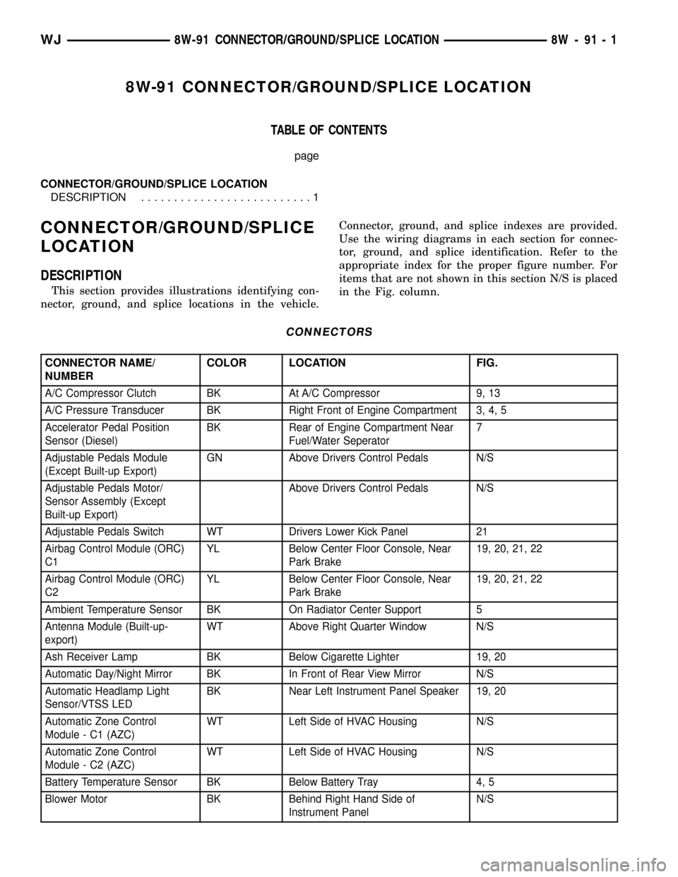
8W-91 CONNECTOR/GROUND/SPLICE LOCATION
TABLE OF CONTENTS
page
CONNECTOR/GROUND/SPLICE LOCATION
DESCRIPTION..........................1
CONNECTOR/GROUND/SPLICE
LOCATION
DESCRIPTION
This section provides illustrations identifying con-
nector, ground, and splice locations in the vehicle.Connector, ground, and splice indexes are provided.
Use the wiring diagrams in each section for connec-
tor, ground, and splice identification. Refer to the
appropriate index for the proper figure number. For
items that are not shown in this section N/S is placed
in the Fig. column.
CONNECTORS
CONNECTOR NAME/
NUMBERCOLOR LOCATION FIG.
A/C Compressor Clutch BK At A/C Compressor 9, 13
A/C Pressure Transducer BK Right Front of Engine Compartment 3, 4, 5
Accelerator Pedal Position
Sensor (Diesel)BK Rear of Engine Compartment Near
Fuel/Water Seperator7
Adjustable Pedals Module
(Except Built-up Export)GN Above Drivers Control Pedals N/S
Adjustable Pedals Motor/
Sensor Assembly (Except
Built-up Export)Above Drivers Control Pedals N/S
Adjustable Pedals Switch WT Drivers Lower Kick Panel 21
Airbag Control Module (ORC)
C1YL Below Center Floor Console, Near
Park Brake19, 20, 21, 22
Airbag Control Module (ORC)
C2YL Below Center Floor Console, Near
Park Brake19, 20, 21, 22
Ambient Temperature Sensor BK On Radiator Center Support 5
Antenna Module (Built-up-
export)WT Above Right Quarter Window N/S
Ash Receiver Lamp BK Below Cigarette Lighter 19, 20
Automatic Day/Night Mirror BK In Front of Rear View Mirror N/S
Automatic Headlamp Light
Sensor/VTSS LEDBK Near Left Instrument Panel Speaker 19, 20
Automatic Zone Control
Module - C1 (AZC)WT Left Side of HVAC Housing N/S
Automatic Zone Control
Module - C2 (AZC)WT Left Side of HVAC Housing N/S
Battery Temperature Sensor BK Below Battery Tray 4, 5
Blower Motor BK Behind Right Hand Side of
Instrument PanelN/S
WJ8W-91 CONNECTOR/GROUND/SPLICE LOCATION 8W - 91 - 1
Page 1187 of 2199
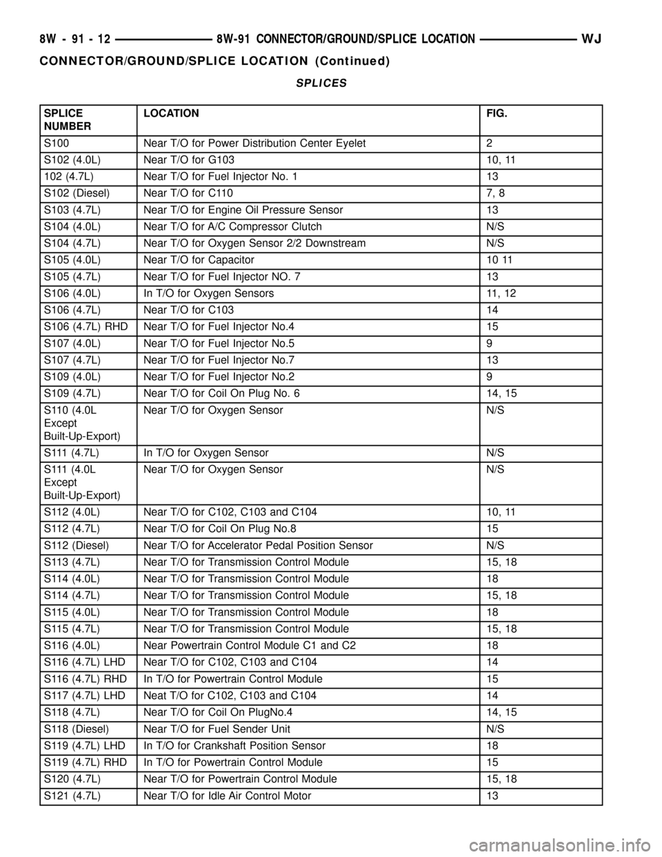
SPLICES
SPLICE
NUMBERLOCATION FIG.
S100 Near T/O for Power Distribution Center Eyelet 2
S102 (4.0L) Near T/O for G103 10, 11
102 (4.7L) Near T/O for Fuel Injector No. 1 13
S102 (Diesel) Near T/O for C110 7, 8
S103 (4.7L) Near T/O for Engine Oil Pressure Sensor 13
S104 (4.0L) Near T/O for A/C Compressor Clutch N/S
S104 (4.7L) Near T/O for Oxygen Sensor 2/2 Downstream N/S
S105 (4.0L) Near T/O for Capacitor 10 11
S105 (4.7L) Near T/O for Fuel Injector NO. 7 13
S106 (4.0L) In T/O for Oxygen Sensors 11, 12
S106 (4.7L) Near T/O for C103 14
S106 (4.7L) RHD Near T/O for Fuel Injector No.4 15
S107 (4.0L) Near T/O for Fuel Injector No.5 9
S107 (4.7L) Near T/O for Fuel Injector No.7 13
S109 (4.0L) Near T/O for Fuel Injector No.2 9
S109 (4.7L) Near T/O for Coil On Plug No. 6 14, 15
S110 (4.0L
Except
Built-Up-Export)Near T/O for Oxygen Sensor N/S
S111 (4.7L) In T/O for Oxygen Sensor N/S
S111 (4.0L
Except
Built-Up-Export)Near T/O for Oxygen Sensor N/S
S112 (4.0L) Near T/O for C102, C103 and C104 10, 11
S112 (4.7L) Near T/O for Coil On Plug No.8 15
S112 (Diesel) Near T/O for Accelerator Pedal Position Sensor N/S
S113 (4.7L) Near T/O for Transmission Control Module 15, 18
S114 (4.0L) Near T/O for Transmission Control Module 18
S114 (4.7L) Near T/O for Transmission Control Module 15, 18
S115 (4.0L) Near T/O for Transmission Control Module 18
S115 (4.7L) Near T/O for Transmission Control Module 15, 18
S116 (4.0L) Near Powertrain Control Module C1 and C2 18
S116 (4.7L) LHD Near T/O for C102, C103 and C104 14
S116 (4.7L) RHD In T/O for Powertrain Control Module 15
S117 (4.7L) LHD Neat T/O for C102, C103 and C104 14
S118 (4.7L) Near T/O for Coil On PlugNo.4 14, 15
S118 (Diesel) Near T/O for Fuel Sender Unit N/S
S119 (4.7L) LHD In T/O for Crankshaft Position Sensor 18
S119 (4.7L) RHD In T/O for Powertrain Control Module 15
S120 (4.7L) Near T/O for Powertrain Control Module 15, 18
S121 (4.7L) Near T/O for Idle Air Control Motor 13
8W - 91 - 12 8W-91 CONNECTOR/GROUND/SPLICE LOCATIONWJ
CONNECTOR/GROUND/SPLICE LOCATION (Continued)
Page 1252 of 2199

DIAGNOSIS AND TESTINGÐREAR SEAL AREA
LEAKS
Since it is sometimes difficult to determine the
source of an oil leak in the rear seal area of the
engine, a more involved inspection is necessary. The
following steps should be followed to help pinpoint
the source of the leak.
If the leakage occurs at the crankshaft rear oil seal
area:
(1) Disconnect the battery.
(2) Raise the vehicle.
(3) Remove torque converter or clutch housing
cover and inspect rear of block for evidence of oil.
Use a black light to check for the oil leak:
(a) Circular spray pattern generally indicates
seal leakage or crankshaft damage.
(b) Where leakage tends to run straight down,
possible causes are a porous block, distributor seal,
camshaft bore cup plugs, oil galley pipe plugs, oil
filter runoff, and main bearing cap to cylinder
block mating surfaces.
(4) If no leaks are detected, pressurized the crank-
case as outlined in (Refer to 9 - ENGINE/LUBRICA-
TION - DIAGNOSIS AND TESTING)
CAUTION: Do not exceed 20.6 kPa (3 psi).
(5) If the leak is not detected, very slowly turn the
crankshaft and watch for leakage. If a leak is
detected between the crankshaft and seal while
slowly turning the crankshaft, it is possible the
crankshaft seal surface is damaged. The seal area on
the crankshaft could have minor nicks or scratches
that can be polished out with emery cloth.
CAUTION: Use extreme caution when crankshaft
polishing is necessary to remove minor nicks or
scratches. The crankshaft seal flange is specially
machined to complement the function of the rear oil
seal.
(6) For bubbles that remain steady with shaft
rotation, no further inspection can be done until dis-
assembled. Refer to the service DiagnosisÐMechani-
cal, under the Oil Leak row, for components
inspections on possible causes and corrections.
(7) After the oil leak root cause and appropriate
corrective action have been identified, (Refer to 9 -
ENGINE/ENGINE BLOCK/CRANKSHAFT OIL
SEAL - REAR - REMOVAL), for proper replacement
procedures.
STANDARD PROCEDURE
STANDARD PROCEDURE - FORM-IN-PLACE
GASKETS AND SEALERS
There are numerous places where form-in-place
gaskets are used on the engine. Care must be taken
when applying form-in-place gaskets to assure
obtaining the desired results.Do not use form-in-
place gasket material unless specified.Bead size,
continuity, and location are of great importance. Too
thin a bead can result in leakage while too much can
result in spill-over which can break off and obstruct
fluid feed lines. A continuous bead of the proper
width is essential to obtain a leak-free gasket.
There are numerous types of form-in-place gasket
materials that are used in the engine area. Mopart
Engine RTV GEN II, MopartATF-RTV, and Mopart
Gasket Maker gasket materials, each have different
properties and can not be used in place of the other.
MOPARtENGINE RTV GEN II
MopartEngine RTV GEN II is used to seal com-
ponents exposed to engine oil. This material is a spe-
cially designed black silicone rubber RTV that
retains adhesion and sealing properties when
exposed to engine oil. Moisture in the air causes the
material to cure. This material is available in three
ounce tubes and has a shelf life of one year. After one
year this material will not properly cure. Always
inspect the package for the expiration date before
use.
MOPARtATF RTV
MopartATF RTV is a specifically designed black
silicone rubber RTV that retains adhesion and seal-
ing properties to seal components exposed to auto-
matic transmission fluid, engine coolants, and
moisture. This material is available in three ounce
tubes and has a shelf life of one year. After one year
this material will not properly cure. Always inspect
the package for the expiration date before use.
MOPARtGASKET MAKER
MopartGasket Maker is an anaerobic type gasket
material. The material cures in the absence of air
when squeezed between two metallic surfaces. It will
not cure if left in the uncovered tube. The anaerobic
material is for use between two machined surfaces.
Do not use on flexible metal flanges.
MOPARtGASKET SEALANT
MopartGasket Sealant is a slow drying, perma-
nently soft sealer. This material is recommended for
sealing threaded fittings and gaskets against leakage
of oil and coolant. Can be used on threaded and
machined parts under all temperatures. This mate-
rial is used on engines with multi-layer steel (MLS)
cylinder head gaskets. This material also will pre-
vent corrosion. MopartGasket Sealant is available in
a 13 oz. aerosol can or 4oz./16 oz. can w/applicator.
WJENGINE - 4.0L 9 - 9
ENGINE - 4.0L (Continued)