2002 JEEP GRAND CHEROKEE Round plug
[x] Cancel search: Round plugPage 1534 of 2199

TEST CONDITION INDICATION
Governor pressure low at
all mph figuresFaulty governor pressure
solenoid, transmission
control module, or
governor pressure
sensor
Lubrication pressure low
at all throttle positionsClogged fluid cooler or
lines, seal rings leaking,
worn pump bushings,
pump, clutch retainer, or
clogged filter.
Line pressure high Output shaft plugged,
sticky regulator valve
Line pressure low Sticky regulator valve,
clogged filter, worn pump
DIAGNOSIS AND TESTING - AIR CHECKING
TRANSMISSION CLUTCH AND BAND
OPERATION
Air-pressure testing can be used to check transmis-
sion front/rear clutch and band operation. The test
can be conducted with the transmission either in the
vehicle or on the work bench, as a final check, after
overhaul.
Air-pressure testing requires that the oil pan and
valve body be removed from the transmission. The
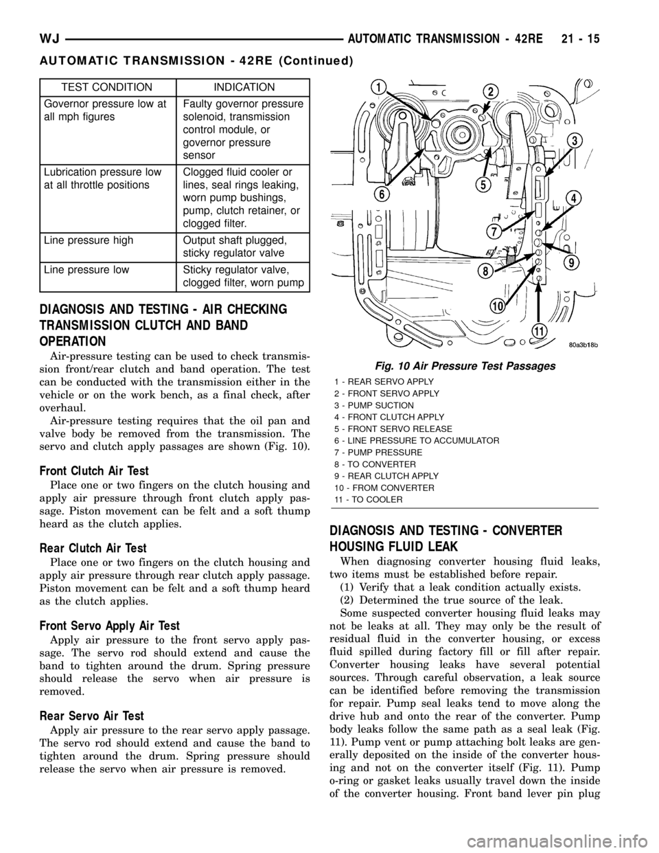
servo and clutch apply passages are shown (Fig. 10).
Front Clutch Air Test
Place one or two fingers on the clutch housing and
apply air pressure through front clutch apply pas-
sage. Piston movement can be felt and a soft thump
heard as the clutch applies.
Rear Clutch Air Test
Place one or two fingers on the clutch housing and
apply air pressure through rear clutch apply passage.
Piston movement can be felt and a soft thump heard
as the clutch applies.
Front Servo Apply Air Test
Apply air pressure to the front servo apply pas-
sage. The servo rod should extend and cause the
band to tighten around the drum. Spring pressure
should release the servo when air pressure is
removed.
Rear Servo Air Test
Apply air pressure to the rear servo apply passage.
The servo rod should extend and cause the band to
tighten around the drum. Spring pressure should
release the servo when air pressure is removed.
DIAGNOSIS AND TESTING - CONVERTER
HOUSING FLUID LEAK
When diagnosing converter housing fluid leaks,
two items must be established before repair.
(1) Verify that a leak condition actually exists.
(2) Determined the true source of the leak.
Some suspected converter housing fluid leaks may
not be leaks at all. They may only be the result of
residual fluid in the converter housing, or excess
fluid spilled during factory fill or fill after repair.
Converter housing leaks have several potential
sources. Through careful observation, a leak source
can be identified before removing the transmission
for repair. Pump seal leaks tend to move along the
drive hub and onto the rear of the converter. Pump
body leaks follow the same path as a seal leak (Fig.
11). Pump vent or pump attaching bolt leaks are gen-
erally deposited on the inside of the converter hous-
ing and not on the converter itself (Fig. 11). Pump
o-ring or gasket leaks usually travel down the inside
of the converter housing. Front band lever pin plug
Fig. 10 Air Pressure Test Passages
1 - REAR SERVO APPLY
2 - FRONT SERVO APPLY
3 - PUMP SUCTION
4 - FRONT CLUTCH APPLY
5 - FRONT SERVO RELEASE
6 - LINE PRESSURE TO ACCUMULATOR
7 - PUMP PRESSURE
8 - TO CONVERTER
9 - REAR CLUTCH APPLY
10 - FROM CONVERTER
11 - TO COOLER
WJAUTOMATIC TRANSMISSION - 42RE 21 - 15
AUTOMATIC TRANSMISSION - 42RE (Continued)
Page 1535 of 2199

leaks are generally deposited on the housing and not
on the converter.
TORQUE CONVERTER LEAK POINTS
Possible sources of converter leaks are:
(1) Leaks at the weld joint around the outside
diameter weld (Fig. 12).
(2) Leaks at the converter hub weld (Fig. 12).
CONVERTER HOUSING AREA LEAK CORRECTION
(1) Remove converter.
(2) Tighten front band adjusting screw until band
is tight around front clutch retainer. This prevents
front/rear clutches from coming out when oil pump is
removed.
(3) Remove oil pump and remove pump seal.
Inspect pump housing drainback and vent holes for
obstructions. Clear holes with solvent and wire.
(4) Inspect pump bushing and converter hub. If
bushing is scored, replace it. If converter hub is
scored, either polish it with crocus cloth or replace
converter.(5) Install new pump seal, O-ring, and gasket.
Replace oil pump if cracked, porous or damaged in
any way. Be sure to loosen the front band before
installing the oil pump, damage to the oil pump seal
may occur if the band is still tightened to the front
clutch retainer.
(6) Loosen kickdown lever pin access plug three
turns. Apply LoctiteŸ 592, or PermatextNo.2to
plug threads and tighten plug to 17 N´m (150 in. lbs.)
torque.
(7) Adjust front band.
(8) Lubricate pump seal and converter hub with
transmission fluid or petroleum jelly and install con-
verter.
(9) Install transmission and converter housing
dust shield.
(10) Lower vehicle.
DIAGNOSIS AND TESTING - DIAGNOSIS
CHARTS
The diagnosis charts provide additional reference
when diagnosing a transmission fault. The charts
provide general information on a variety of transmis-
sion, overdrive unit and converter clutch fault condi-
tions.
The hydraulic flow charts in the Schematics and
Diagrams section of this group, outline fluid flow and
hydraulic circuitry. Circuit operation is provided for
PARK, NEUTRAL, FIRST, SECOND, THIRD,
FOURTH, MANUAL FIRST, MANUAL SECOND,
and REVERSE gear ranges. Normal working pres-
sures are also supplied for each of the gear ranges.
Fig. 11 Converter Housing Leak Paths
1 - PUMP SEAL
2 - PUMP VENT
3 - PUMP BOLT
4 - PUMP GASKET
5 - CONVERTER HOUSING
6 - CONVERTER
7 - REAR MAIN SEAL LEAK
Fig. 12 Converter Leak Points - Typical
1 - OUTSIDE DIAMETER WELD
2 - TORQUE CONVERTER HUB WELD
3 - STARTER RING GEAR
4 - LUG
21 - 16 AUTOMATIC TRANSMISSION - 42REWJ
AUTOMATIC TRANSMISSION - 42RE (Continued)
Page 1542 of 2199

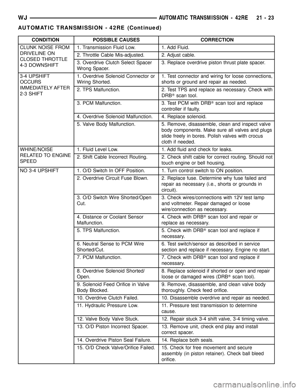
CONDITION POSSIBLE CAUSES CORRECTION
CLUNK NOISE FROM
DRIVELINE ON
CLOSED THROTTLE
4-3 DOWNSHIFT1. Transmission Fluid Low. 1. Add Fluid.
2. Throttle Cable Mis-adjusted. 2. Adjust cable.
3. Overdrive Clutch Select Spacer
Wrong Spacer.3. Replace overdrive piston thrust plate spacer.
3-4 UPSHIFT
OCCURS
IMMEDIATELY AFTER
2-3 SHIFT1. Overdrive Solenoid Connector or
Wiring Shorted.1.
Test connector and wiring for loose connections,
shorts or ground and repair as needed.
2. TPS Malfunction. 2. Test TPS and replace as necessary. Check with
DRBTscan tool.
3. PCM Malfunction. 3. Test PCM with DRBTscan tool and replace
controller if faulty.
4. Overdrive Solenoid Malfunction. 4. Replace solenoid.
5. Valve Body Malfunction. 5. Remove, disassemble, clean and inspect valve
body components. Make sure all valves and plugs
slide freely in bores. Polish valves with crocus
cloth if needed.
WHINE/NOISE
RELATED TO ENGINE
SPEED1. Fluid Level Low. 1. Add fluid and check for leaks.
2. Shift Cable Incorrect Routing. 2. Check shift cable for correct routing. Should not
touch engine or bell housing.
NO 3-4 UPSHIFT 1. O/D Switch In OFF Position. 1. Turn control switch to ON position.
2. Overdrive Circuit Fuse Blown. 2. Replace fuse. Determine why fuse failed and
repair as necessary (i.e., shorts or grounds in
circuit).
3. O/D Switch Wire Shorted/Open
Cut.3. Check wires/connections with 12V test lamp
and voltmeter. Repair damaged or loose
wire/connection as necessary.
4. Distance or Coolant Sensor
Malfunction.4. Check with DRBTscan tool and repair or
replace as necessary.
5. TPS Malfunction. 5. Check with DRBTscan tool and replace if
necessary.
6. Neutral Sense to PCM Wire
Shorted/Cut.6. Test switch/sensor as described in service
section and replace if necessary. Engine no start.
7. PCM Malfunction. 7. Check with DRBTscan tool and replace if
necessary.
8. Overdrive Solenoid Shorted/
Open.8. Replace solenoid if shorted or open and repair
loose or damaged wires (DRBTscan tool).
9. Solenoid Feed Orifice in Valve
Body Blocked.9. Remove, disassemble, and clean valve body
thoroughly. Check feed orifice.
10. Overdrive Clutch Failed. 10. Disassemble overdrive and repair as needed.
11. Hydraulic Pressure Low. 11. Pressure test transmission to determine
cause.
12. Valve Body Valve Stuck. 12. Repair stuck 3-4 shift valve, 3-4 timing valve.
13. O/D Piston Incorrect Spacer. 13. Remove unit, check end play and install
correct spacer.
14. Overdrive Piston Seal Failure. 14. Replace both seals.
15. O/D Check Valve/Orifice Failed. 15. Check for free movement and secure
assembly (in piston retainer). Check ball bleed
orifice.
WJAUTOMATIC TRANSMISSION - 42RE 21 - 23
AUTOMATIC TRANSMISSION - 42RE (Continued)
Page 1543 of 2199

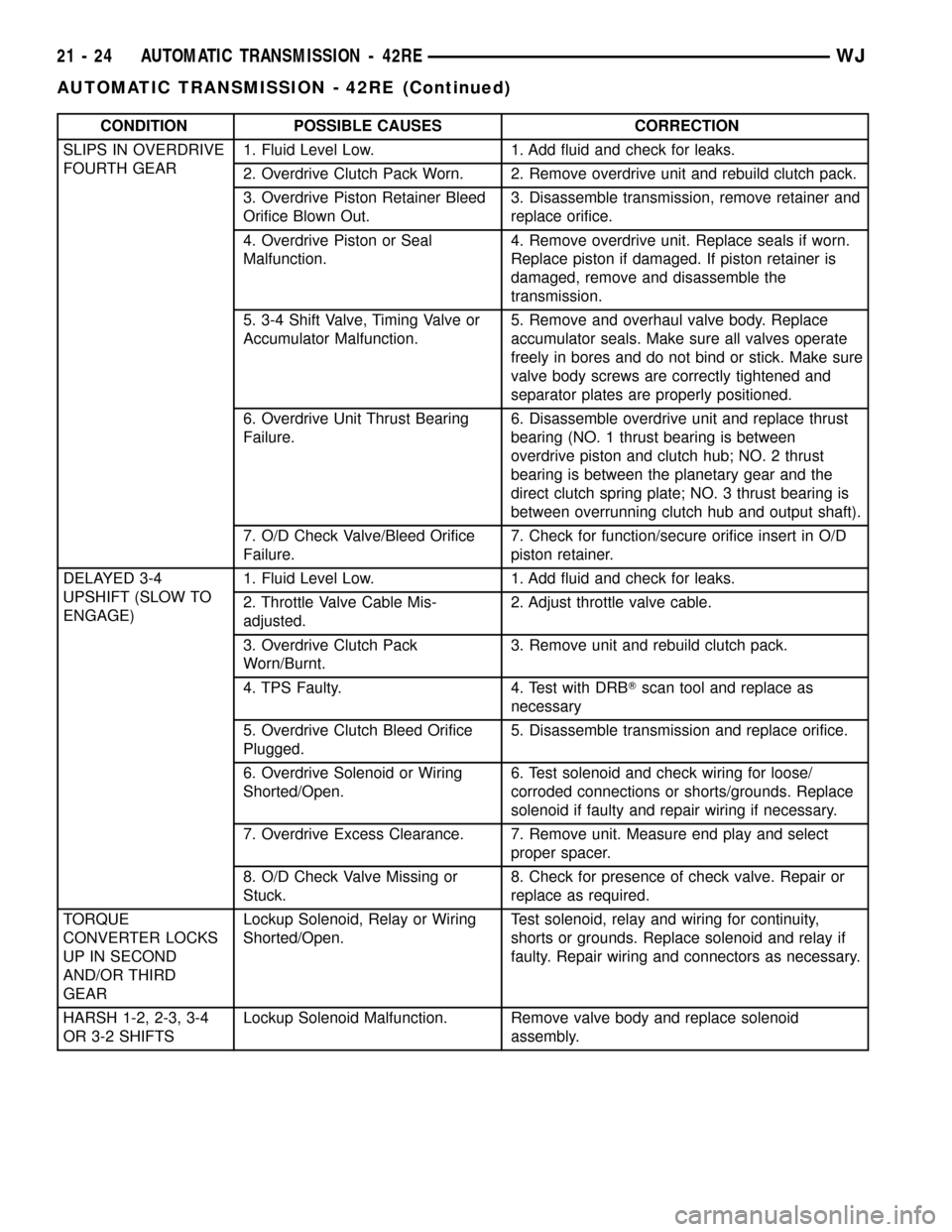
CONDITION POSSIBLE CAUSES CORRECTION
SLIPS IN OVERDRIVE
FOURTH GEAR1. Fluid Level Low. 1. Add fluid and check for leaks.
2. Overdrive Clutch Pack Worn. 2. Remove overdrive unit and rebuild clutch pack.
3. Overdrive Piston Retainer Bleed
Orifice Blown Out.3. Disassemble transmission, remove retainer and
replace orifice.
4. Overdrive Piston or Seal
Malfunction.4. Remove overdrive unit. Replace seals if worn.
Replace piston if damaged. If piston retainer is
damaged, remove and disassemble the
transmission.
5. 3-4 Shift Valve, Timing Valve or
Accumulator Malfunction.5. Remove and overhaul valve body. Replace
accumulator seals. Make sure all valves operate
freely in bores and do not bind or stick. Make sure
valve body screws are correctly tightened and
separator plates are properly positioned.
6. Overdrive Unit Thrust Bearing
Failure.6. Disassemble overdrive unit and replace thrust
bearing (NO. 1 thrust bearing is between
overdrive piston and clutch hub; NO. 2 thrust
bearing is between the planetary gear and the
direct clutch spring plate; NO. 3 thrust bearing is
between overrunning clutch hub and output shaft).
7. O/D Check Valve/Bleed Orifice
Failure.7. Check for function/secure orifice insert in O/D
piston retainer.
DELAYED 3-4
UPSHIFT (SLOW TO
ENGAGE)1. Fluid Level Low. 1. Add fluid and check for leaks.
2. Throttle Valve Cable Mis-
adjusted.2. Adjust throttle valve cable.
3. Overdrive Clutch Pack
Worn/Burnt.3. Remove unit and rebuild clutch pack.
4. TPS Faulty. 4. Test with DRBTscan tool and replace as
necessary
5. Overdrive Clutch Bleed Orifice
Plugged.5. Disassemble transmission and replace orifice.
6. Overdrive Solenoid or Wiring
Shorted/Open.6. Test solenoid and check wiring for loose/
corroded connections or shorts/grounds. Replace
solenoid if faulty and repair wiring if necessary.
7. Overdrive Excess Clearance. 7. Remove unit. Measure end play and select
proper spacer.
8. O/D Check Valve Missing or
Stuck.8. Check for presence of check valve. Repair or
replace as required.
TORQUE
CONVERTER LOCKS
UP IN SECOND
AND/OR THIRD
GEARLockup Solenoid, Relay or Wiring
Shorted/Open.Test solenoid, relay and wiring for continuity,
shorts or grounds. Replace solenoid and relay if
faulty. Repair wiring and connectors as necessary.
HARSH 1-2, 2-3, 3-4
OR 3-2 SHIFTSLockup Solenoid Malfunction. Remove valve body and replace solenoid
assembly.
21 - 24 AUTOMATIC TRANSMISSION - 42REWJ
AUTOMATIC TRANSMISSION - 42RE (Continued)
Page 1658 of 2199

OPERATION
NOTE: Refer to the Hydraulic Schematics for a
visual aid in determining valve location, operation
and design.
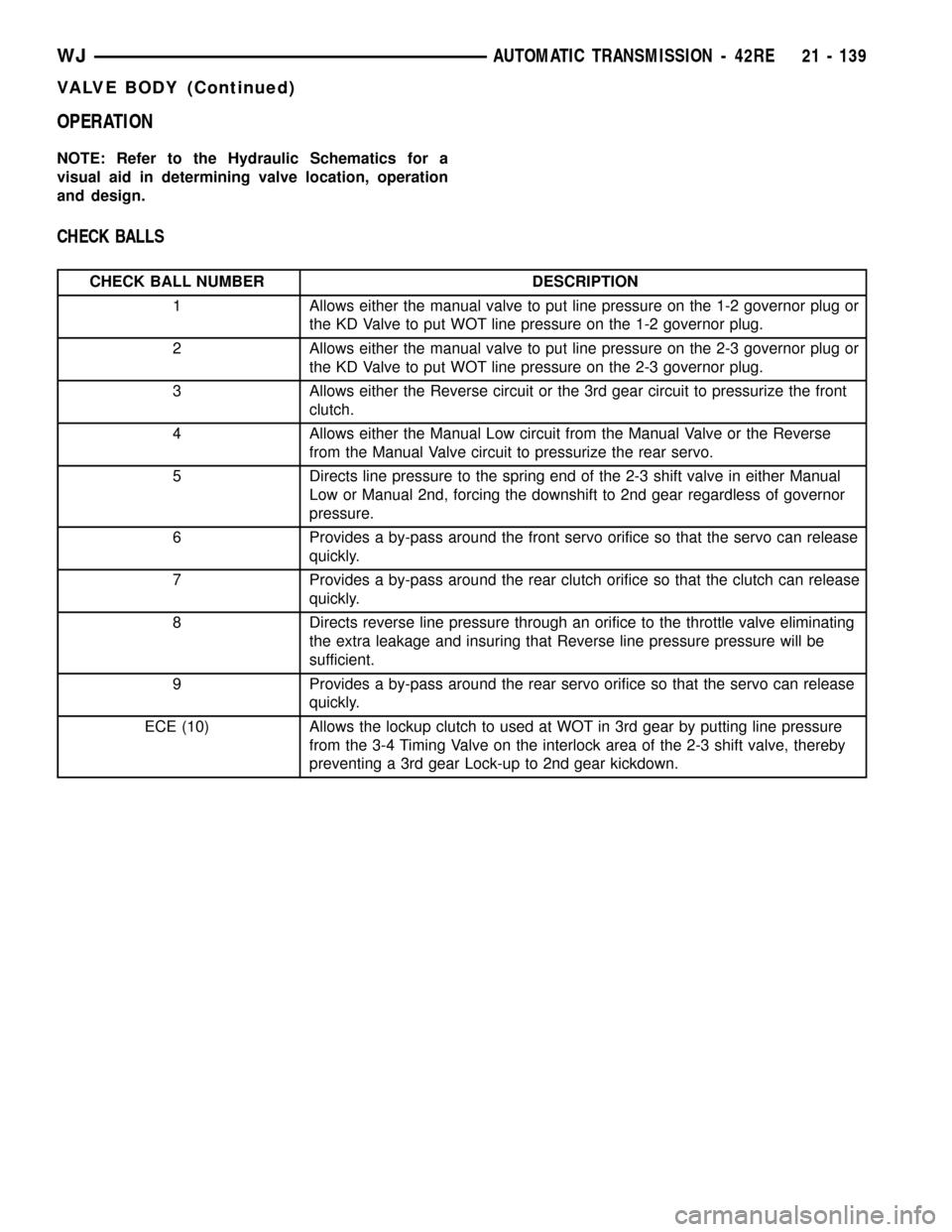
CHECK BALLS
CHECK BALL NUMBER DESCRIPTION
1 Allows either the manual valve to put line pressure on the 1-2 governor plug or
the KD Valve to put WOT line pressure on the 1-2 governor plug.
2 Allows either the manual valve to put line pressure on the 2-3 governor plug or
the KD Valve to put WOT line pressure on the 2-3 governor plug.
3 Allows either the Reverse circuit or the 3rd gear circuit to pressurize the front
clutch.
4 Allows either the Manual Low circuit from the Manual Valve or the Reverse
from the Manual Valve circuit to pressurize the rear servo.
5 Directs line pressure to the spring end of the 2-3 shift valve in either Manual
Low or Manual 2nd, forcing the downshift to 2nd gear regardless of governor
pressure.
6 Provides a by-pass around the front servo orifice so that the servo can release
quickly.
7 Provides a by-pass around the rear clutch orifice so that the clutch can release
quickly.
8 Directs reverse line pressure through an orifice to the throttle valve eliminating
the extra leakage and insuring that Reverse line pressure pressure will be
sufficient.
9 Provides a by-pass around the rear servo orifice so that the servo can release
quickly.
ECE (10) Allows the lockup clutch to used at WOT in 3rd gear by putting line pressure
from the 3-4 Timing Valve on the interlock area of the 2-3 shift valve, thereby
preventing a 3rd gear Lock-up to 2nd gear kickdown.
WJAUTOMATIC TRANSMISSION - 42RE 21 - 139
VALVE BODY (Continued)
Page 1681 of 2199

VALVE BODY UPPER HOUSING
(1) Note location of check balls in valve body upper
housing (Fig. 305). Then remove the one large diam-
eter and the six smaller diameter check balls.
(2) Remove governor plug and shuttle valve covers
(Fig. 307).
(3) Remove E-clip that secures shuttle valve sec-
ondary spring on valve stem (Fig. 306).
(4) Remove throttle plug, primary spring, shuttle
valve, secondary spring, and spring guides (Fig. 307).
(5) Remove boost valve retainer, spring and valve
if not previously removed.
(6) Remove throttle plug and 1-2 and 2-3 governor
plugs (Fig. 294).
(7) Turn upper housing around and remove limit
valve and shift valve covers (Fig. 308).
(8) Remove limit valve housing. Then remove
retainer, spring, limit valve, and 2-3 throttle plug
from limit valve housing (Fig. 308).(9) Remove 1-2 shift control valve and spring (Fig.
308).
(10) Remove 1-2 shift valve and spring (Fig. 308).
(11) Remove 2-3 shift valve and spring from valve
body (Fig. 308).
(12) Remove pressure plug cover (Fig. 308).
(13) Remove line pressure plug, sleeve, throttle
pressure plug and spring (Fig. 308).
Fig. 305 Check Ball Locations In Upper Housing
1 - SMALL DIAMETER CHECK BALLS (6)
2 - LARGE DIAMETER CHECK BALL (1)
Fig. 306 Shuttle Valve E-Clip And Secondary Spring
Location
1 - E-CLIP
2 - SECONDARY SPRING AND GUIDES
3 - SHUTTLE VALVE
21 - 162 AUTOMATIC TRANSMISSION - 42REWJ
VALVE BODY (Continued)
Page 1685 of 2199

Wipe the governor pressure sensor and solenoid
valve with dry, lint free shop towels only. The O-rings
on the sensor and solenoid valve are the only service-
able components. Be sure the vent ports in the sole-
noid valve are open and not blocked by dirt or debris.
Replace the valve and/or sensor only when DRB scan
tool diagnosis indicates this is necessary. Or, if either
part has sustained physical damage (dented,
deformed, broken, etc.).
CAUTION: Do not turn the small screw at the end of
the solenoid valve for any reason. Turning the
screw in either direction will ruin solenoid calibra-
tion and result in solenoid failure. In addition, the
filter on the solenoid valve is NOT serviceable. Do
not try to remove the filter as this will damage the
valve housing.
INSPECTION
Inspect the throttle and manual valve levers and
shafts. Do not attempt to straighten a bent shaft or
correct a loose lever. Replace these components if
worn, bent, loose or damaged in any way.
Inspect all of the valve body mating surfaces for
scratches, nicks, burrs, or distortion. Use a straight-
edge to check surface flatness. Minor scratches may
be removed with crocus cloth using only very light
pressure.Minor distortion of a valve body mating surface
may be corrected by smoothing the surface with a
sheet of crocus cloth. Position the crocus cloth on a
surface plate, sheet of plate glass or equally flat sur-
face. If distortion is severe or any surfaces are
heavily scored, the valve body will have to be
replaced.
CAUTION: Many of the valves and plugs, such as
the throttle valve, shuttle valve plug, 1-2 shift valve
and 1-2 governor plug, are made of coated alumi-
num. Aluminum components are identified by the
dark color of the special coating applied to the sur-
face (or by testing with a magnet). Do not sand alu-
minum valves or plugs under any circumstances.
This practice could damage the special coating
causing the valves/plugs to stick and bind.
Inspect the valves and plugs for scratches, burrs,
nicks, or scores. Minor surface scratches on steel
valves and plugs can be removed with crocus cloth
butdo not round off the edges of the valve or
plug lands.Maintaining sharpness of these edges is
vitally important. The edges prevent foreign matter
from lodging between the valves and plugs and the
bore.
Inspect all the valve and plug bores in the valve
body. Use a penlight to view the bore interiors.
Replace the valve body if any bores are distorted or
scored. Inspect all of the valve body springs. The
springs must be free of distortion, warpage or broken
coils.
Check the two separator plates for distortion or
damage of any kind. Inspect the upper housing,
lower housing, 3-4 accumulator housing, and transfer
plate carefully. Be sure all fluid passages are clean
and clear. Check condition of the upper housing and
transfer plate check balls as well. The check balls
and ball seats must not be worn or damaged.
Trial fit each valve and plug in its bore to check
freedom of operation. When clean and dry, the valves
and plugs should drop freely into the bores.
Valve body bores do not change dimensionally with
use. If the valve body functioned correctly when new,
it will continue to operate properly after cleaning and
inspection. It should not be necessary to replace a
valve body assembly unless it is damaged in han-
dling.
The only serviceable valve body components are
listed below. The remaining valve body components
are serviced only as part of a complete valve body
assembly. Serviceable parts are:
²dual solenoid and harness assembly
²solenoid gasket
²solenoid case connector O-rings and shoulder
bolt
²switch valve and spring
Fig. 310 Accumulator Housing Components
1 - ACCUMULATOR PISTON
2 - 3-4 ACCUMULATOR HOUSING
3 - TEFLON SEALS
4 - PISTON SPRING
5 - COVER PLATE AND SCREWS
21 - 166 AUTOMATIC TRANSMISSION - 42REWJ
VALVE BODY (Continued)
Page 1771 of 2199

(9) Remove the oil pump valve retainers and asso-
ciated valve and spring one at a time (Fig. 93) (Fig.
94). Mark the combination of components as a group
and tag them as to the location from which they were
removed.
CLEANING
Clean pump and support components with solvent
and dry them with compressed air.
INSPECTION
Check condition of the seal rings and thrust
washer on the reaction shaft support. The seal rings
do not need to be replaced unless cracked, broken, or
severely worn.
Inspect the pump and support components. Replace
the pump or support if the seal ring grooves or
machined surfaces are worn, scored, pitted, or dam-
aged. Replace the pump gears if pitted, worn
chipped, or damaged.Inspect the pump reaction shaft support bushings.
Replace either bushing only if heavily worn, scored or
damaged. It is not necessary to replace the bushings
unless they are actually damaged.
Inspect the valves and plugs for scratches, burrs,
nicks, or scores. Minor surface scratches on steel
valves and plugs can be removed with crocus cloth
butdo not round off the edges of the valve or
plug lands.Maintaining sharpness of these edges is
vitally important. The edges prevent foreign matter
from lodging between the valves and plugs and the
bore.
Inspect all the valve and plug bores in the oil
pump cover. Use a penlight to view the bore interi-
ors. Replace the oil pump if any bores are distorted
or scored. Inspect all of the valve springs. The
springs must be free of distortion, warpage or broken
coils.
Trial fit each valve and plug in its bore to check
freedom of operation. When clean and dry, the valves
and plugs should drop freely into the bores.
Fig. 93 Oil Pump Valve Body
1 - T/C REGULATOR VALVE
2 - T/C LIMIT VALVE
3 - REGULATOR VALVE
4 - OIL PUMP VALVE BODY
Fig. 94 T/C Switch Valve
1 - RETAINER
2 - T/C SWITCH VALVE
3 - OIL PUMP VALVE BODY
21 - 252 AUTOMATIC TRANSMISSION - 545RFEWJ
OIL PUMP (Continued)