2002 JEEP GRAND CHEROKEE regulator
[x] Cancel search: regulatorPage 1884 of 2199
DOOR - FRONT
TABLE OF CONTENTS
page page
CHECK STRAP
REMOVAL.............................11
INSTALLATION.........................11
DOOR
REMOVAL.............................12
INSTALLATION.........................12
ADJUSTMENTS
DOOR ADJUSTMENT..................12
DOOR GLASS
REMOVAL.............................12
INSTALLATION.........................12
EXTERIOR HANDLE
REMOVAL.............................13
INSTALLATION.........................13
GLASS RUN CHANNEL
REMOVAL.............................13
INSTALLATION.........................14
HINGE
REMOVAL.............................14
INSTALLATION.........................15
INSIDE HANDLE ACTUATOR
REMOVAL.............................15INSTALLATION.........................15
LATCH
REMOVAL.............................15
INSTALLATION.........................15
ADJUSTMENTS
DOOR LATCH........................16
LATCH STRIKER
REMOVAL.............................16
INSTALLATION.........................16
LOCK CYLINDER
REMOVAL.............................16
INSTALLATION.........................17
TRIM PANEL
REMOVAL.............................17
INSTALLATION.........................17
WATERDAM
REMOVAL.............................17
INSTALLATION.........................17
WINDOW REGULATOR
REMOVAL.............................18
INSTALLATION.........................18
CHECK STRAP
REMOVAL
(1) Remove the waterdam, refer to (Refer to 23 -
BODY/DOOR - FRONT/WATERDAM - REMOVAL).
(2) Remove speaker.
(3) Remove screws attaching door check to A-pillar.
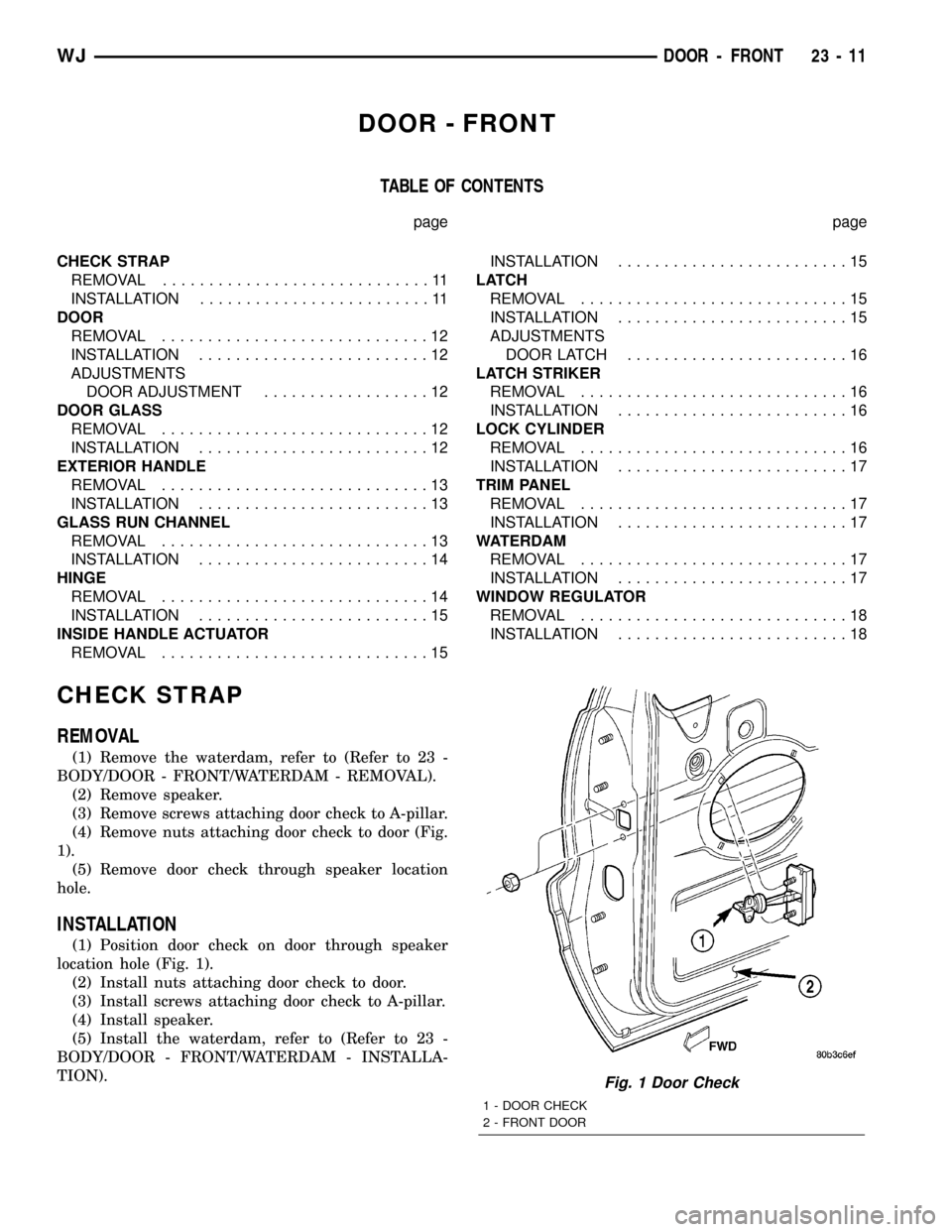
(4) Remove nuts attaching door check to door (Fig.
1).
(5) Remove door check through speaker location
hole.
INSTALLATION
(1) Position door check on door through speaker
location hole (Fig. 1).
(2) Install nuts attaching door check to door.
(3) Install screws attaching door check to A-pillar.
(4) Install speaker.
(5) Install the waterdam, refer to (Refer to 23 -
BODY/DOOR - FRONT/WATERDAM - INSTALLA-
TION).
Fig. 1 Door Check
1 - DOOR CHECK
2 - FRONT DOOR
WJDOOR - FRONT 23 - 11
Page 1885 of 2199
DOOR
REMOVAL
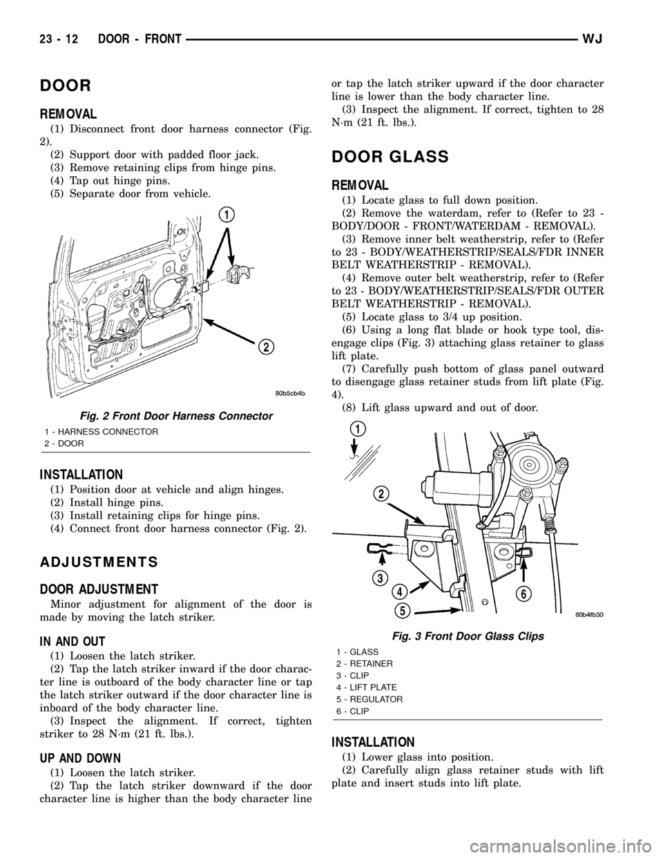
(1) Disconnect front door harness connector (Fig.
2).
(2) Support door with padded floor jack.
(3) Remove retaining clips from hinge pins.
(4) Tap out hinge pins.
(5) Separate door from vehicle.
INSTALLATION
(1) Position door at vehicle and align hinges.
(2) Install hinge pins.
(3) Install retaining clips for hinge pins.
(4) Connect front door harness connector (Fig. 2).
ADJUSTMENTS
DOOR ADJUSTMENT
Minor adjustment for alignment of the door is
made by moving the latch striker.
IN AND OUT
(1) Loosen the latch striker.
(2) Tap the latch striker inward if the door charac-
ter line is outboard of the body character line or tap
the latch striker outward if the door character line is
inboard of the body character line.
(3) Inspect the alignment. If correct, tighten
striker to 28 N´m (21 ft. lbs.).
UP AND DOWN
(1) Loosen the latch striker.
(2) Tap the latch striker downward if the door
character line is higher than the body character lineor tap the latch striker upward if the door character
line is lower than the body character line.
(3) Inspect the alignment. If correct, tighten to 28
N´m (21 ft. lbs.).
DOOR GLASS
REMOVAL
(1) Locate glass to full down position.
(2) Remove the waterdam, refer to (Refer to 23 -
BODY/DOOR - FRONT/WATERDAM - REMOVAL).
(3) Remove inner belt weatherstrip, refer to (Refer
to 23 - BODY/WEATHERSTRIP/SEALS/FDR INNER
BELT WEATHERSTRIP - REMOVAL).
(4) Remove outer belt weatherstrip, refer to (Refer
to 23 - BODY/WEATHERSTRIP/SEALS/FDR OUTER
BELT WEATHERSTRIP - REMOVAL).
(5) Locate glass to 3/4 up position.
(6) Using a long flat blade or hook type tool, dis-
engage clips (Fig. 3) attaching glass retainer to glass
lift plate.
(7) Carefully push bottom of glass panel outward
to disengage glass retainer studs from lift plate (Fig.
4).
(8) Lift glass upward and out of door.
INSTALLATION
(1) Lower glass into position.
(2) Carefully align glass retainer studs with lift
plate and insert studs into lift plate.
Fig. 2 Front Door Harness Connector
1 - HARNESS CONNECTOR
2 - DOOR
Fig. 3 Front Door Glass Clips
1 - GLASS
2 - RETAINER
3 - CLIP
4 - LIFT PLATE
5 - REGULATOR
6 - CLIP
23 - 12 DOOR - FRONTWJ
Page 1887 of 2199
(7) Remove glass run channel from door.
INSTALLATION
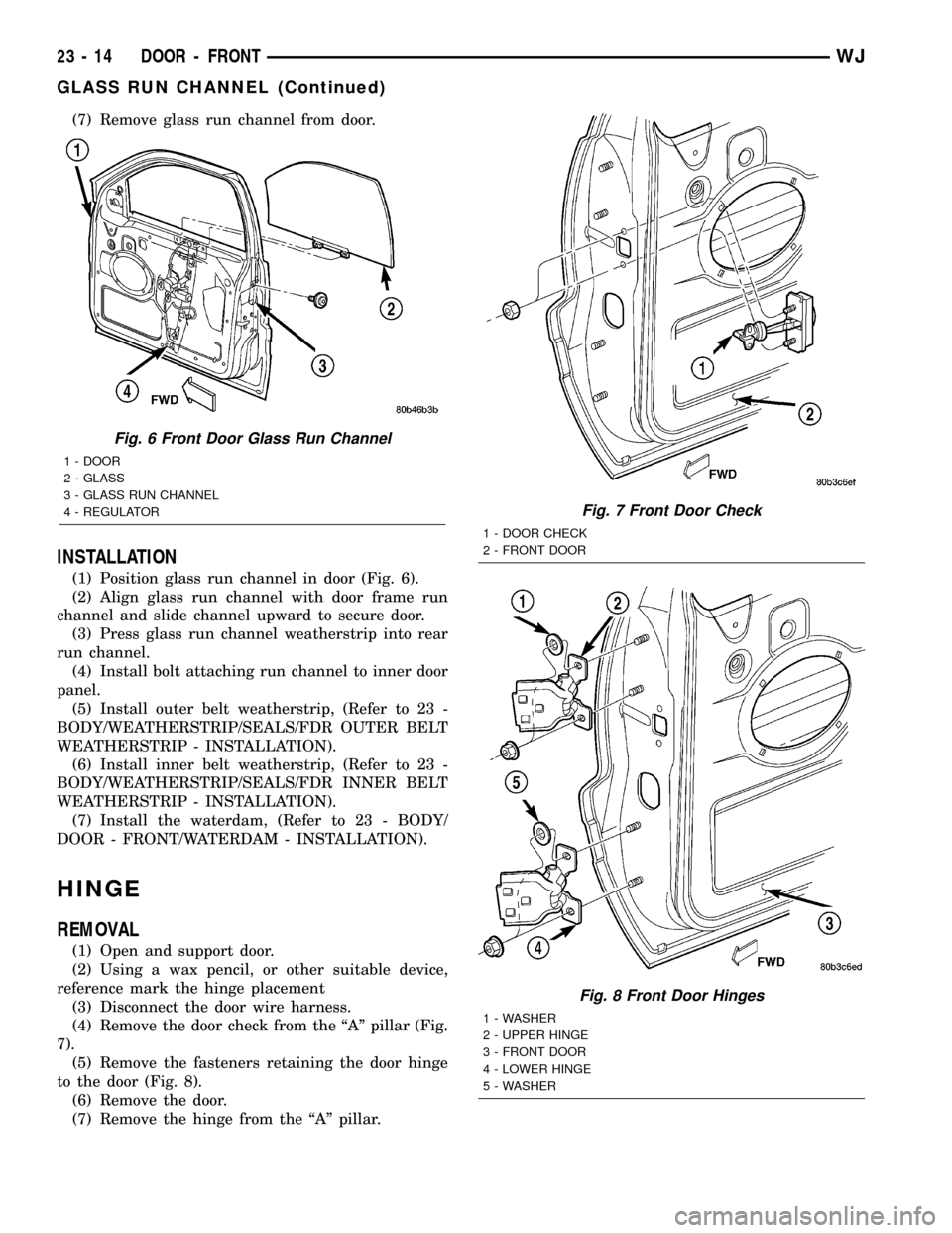
(1) Position glass run channel in door (Fig. 6).
(2) Align glass run channel with door frame run
channel and slide channel upward to secure door.
(3) Press glass run channel weatherstrip into rear
run channel.
(4) Install bolt attaching run channel to inner door
panel.
(5) Install outer belt weatherstrip, (Refer to 23 -
BODY/WEATHERSTRIP/SEALS/FDR OUTER BELT
WEATHERSTRIP - INSTALLATION).
(6) Install inner belt weatherstrip, (Refer to 23 -
BODY/WEATHERSTRIP/SEALS/FDR INNER BELT
WEATHERSTRIP - INSTALLATION).
(7) Install the waterdam, (Refer to 23 - BODY/
DOOR - FRONT/WATERDAM - INSTALLATION).
HINGE
REMOVAL
(1) Open and support door.
(2) Using a wax pencil, or other suitable device,
reference mark the hinge placement
(3) Disconnect the door wire harness.
(4) Remove the door check from the ªAº pillar (Fig.
7).
(5) Remove the fasteners retaining the door hinge
to the door (Fig. 8).
(6) Remove the door.
(7) Remove the hinge from the ªAº pillar.
Fig. 6 Front Door Glass Run Channel
1 - DOOR
2 - GLASS
3 - GLASS RUN CHANNEL
4 - REGULATOR
Fig. 7 Front Door Check
1 - DOOR CHECK
2 - FRONT DOOR
Fig. 8 Front Door Hinges
1 - WASHER
2 - UPPER HINGE
3 - FRONT DOOR
4 - LOWER HINGE
5 - WASHER
23 - 14 DOOR - FRONTWJ
GLASS RUN CHANNEL (Continued)
Page 1891 of 2199
WINDOW REGULATOR
REMOVAL
(1) Remove front door glass, refer to (Refer to 23 -
BODY/DOOR - FRONT/DOOR GLASS - REMOVAL).
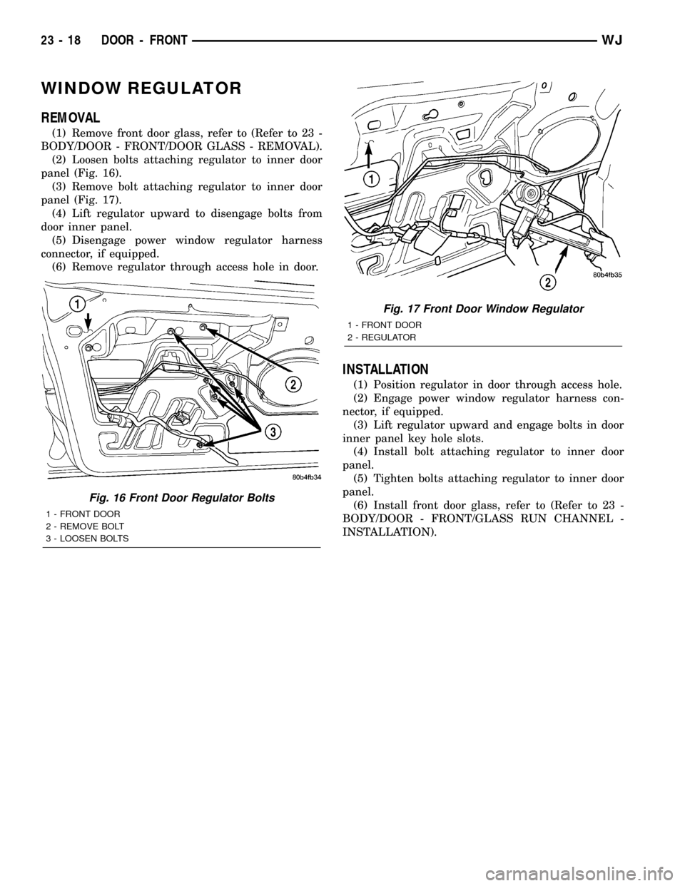
(2) Loosen bolts attaching regulator to inner door
panel (Fig. 16).
(3) Remove bolt attaching regulator to inner door
panel (Fig. 17).
(4) Lift regulator upward to disengage bolts from
door inner panel.
(5) Disengage power window regulator harness
connector, if equipped.
(6) Remove regulator through access hole in door.
INSTALLATION
(1) Position regulator in door through access hole.
(2) Engage power window regulator harness con-
nector, if equipped.
(3) Lift regulator upward and engage bolts in door
inner panel key hole slots.
(4) Install bolt attaching regulator to inner door
panel.
(5) Tighten bolts attaching regulator to inner door
panel.
(6) Install front door glass, refer to (Refer to 23 -
BODY/DOOR - FRONT/GLASS RUN CHANNEL -
INSTALLATION).
Fig. 16 Front Door Regulator Bolts
1 - FRONT DOOR
2 - REMOVE BOLT
3 - LOOSEN BOLTS
Fig. 17 Front Door Window Regulator
1 - FRONT DOOR
2 - REGULATOR
23 - 18 DOOR - FRONTWJ
Page 1892 of 2199
DOORS - REAR
TABLE OF CONTENTS
page page
CHECK STRAP
REMOVAL.............................19
INSTALLATION.........................19
DOOR
REMOVAL.............................20
INSTALLATION.........................20
DOOR GLASS
REMOVAL.............................20
INSTALLATION.........................20
EXTERIOR HANDLE
REMOVAL.............................20
INSTALLATION.........................21
HINGE
REMOVAL.............................21
INSTALLATION.........................21
INSIDE HANDLE ACTUATOR
REMOVAL.............................22INSTALLATION.........................22
LATCH
REMOVAL.............................22
INSTALLATION.........................22
LATCH STRIKER
REMOVAL.............................23
INSTALLATION.........................23
TRIM PANEL
REMOVAL.............................23
INSTALLATION.........................23
WATERDAM
REMOVAL.............................23
INSTALLATION.........................24
WINDOW REGULATOR
REMOVAL.............................24
INSTALLATION.........................24
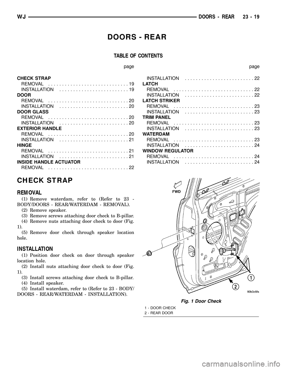
CHECK STRAP
REMOVAL
(1) Remove waterdam, refer to (Refer to 23 -
BODY/DOORS - REAR/WATERDAM - REMOVAL).
(2) Remove speaker.
(3) Remove screws attaching door check to B-pillar.
(4) Remove nuts attaching door check to door (Fig.
1).
(5) Remove door check through speaker location
hole.
INSTALLATION
(1) Position door check on door through speaker
location hole.
(2) Install nuts attaching door check to door (Fig.
1).
(3) Install screws attaching door check to B-pillar.
(4) Install speaker.
(5) Install waterdam, refer to (Refer to 23 - BODY/
DOORS - REAR/WATERDAM - INSTALLATION).
Fig. 1 Door Check
1 - DOOR CHECK
2 - REAR DOOR
WJDOORS - REAR 23 - 19
Page 1893 of 2199
DOOR
REMOVAL
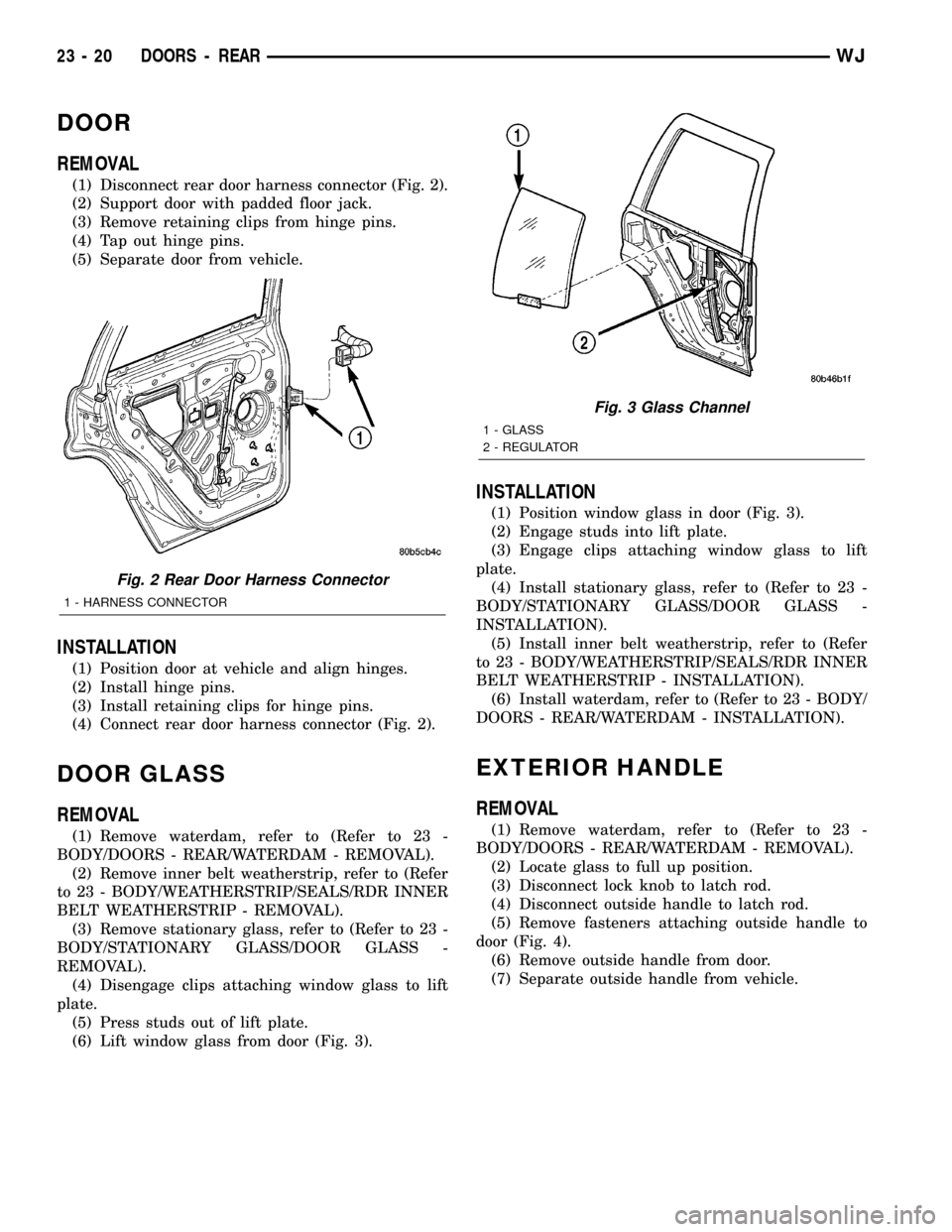
(1) Disconnect rear door harness connector (Fig. 2).
(2) Support door with padded floor jack.
(3) Remove retaining clips from hinge pins.
(4) Tap out hinge pins.
(5) Separate door from vehicle.
INSTALLATION
(1) Position door at vehicle and align hinges.
(2) Install hinge pins.
(3) Install retaining clips for hinge pins.
(4) Connect rear door harness connector (Fig. 2).
DOOR GLASS
REMOVAL
(1) Remove waterdam, refer to (Refer to 23 -
BODY/DOORS - REAR/WATERDAM - REMOVAL).
(2) Remove inner belt weatherstrip, refer to (Refer
to 23 - BODY/WEATHERSTRIP/SEALS/RDR INNER
BELT WEATHERSTRIP - REMOVAL).
(3) Remove stationary glass, refer to (Refer to 23 -
BODY/STATIONARY GLASS/DOOR GLASS -
REMOVAL).
(4) Disengage clips attaching window glass to lift
plate.
(5) Press studs out of lift plate.
(6) Lift window glass from door (Fig. 3).
INSTALLATION
(1) Position window glass in door (Fig. 3).
(2) Engage studs into lift plate.
(3) Engage clips attaching window glass to lift
plate.
(4) Install stationary glass, refer to (Refer to 23 -
BODY/STATIONARY GLASS/DOOR GLASS -
INSTALLATION).
(5) Install inner belt weatherstrip, refer to (Refer
to 23 - BODY/WEATHERSTRIP/SEALS/RDR INNER
BELT WEATHERSTRIP - INSTALLATION).
(6) Install waterdam, refer to (Refer to 23 - BODY/
DOORS - REAR/WATERDAM - INSTALLATION).
EXTERIOR HANDLE
REMOVAL
(1) Remove waterdam, refer to (Refer to 23 -
BODY/DOORS - REAR/WATERDAM - REMOVAL).
(2) Locate glass to full up position.
(3) Disconnect lock knob to latch rod.
(4) Disconnect outside handle to latch rod.
(5) Remove fasteners attaching outside handle to
door (Fig. 4).
(6) Remove outside handle from door.
(7) Separate outside handle from vehicle.
Fig. 2 Rear Door Harness Connector
1 - HARNESS CONNECTOR
Fig. 3 Glass Channel
1 - GLASS
2 - REGULATOR
23 - 20 DOORS - REARWJ
Page 1897 of 2199
INSTALLATION
(1) Waterdam contact surface must be free of con-
taminants. Clean as necessary.
(2) Route all harnesses and linkage rods through
waterdam as necessary.
(3) Position waterdam on door and align all holes
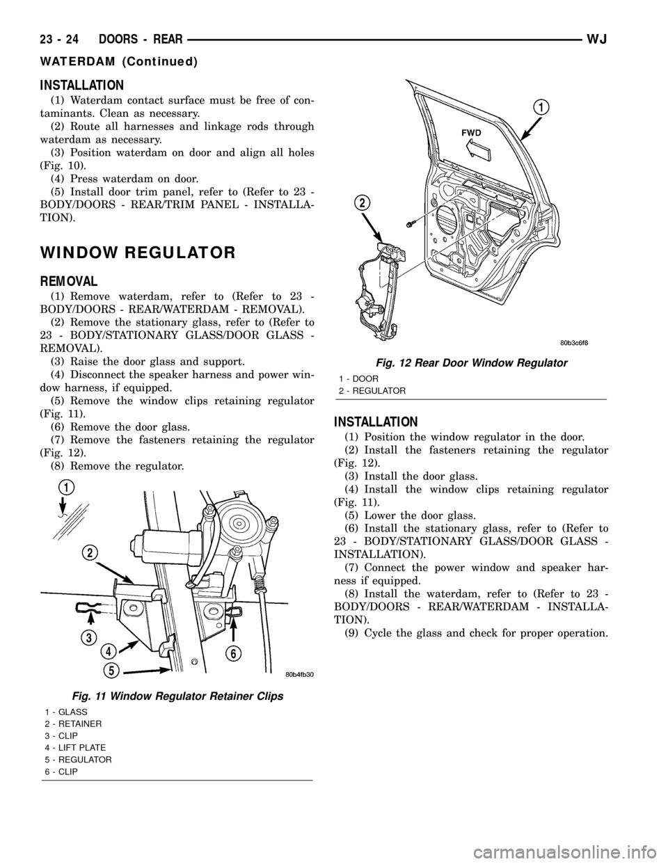
(Fig. 10).
(4) Press waterdam on door.
(5) Install door trim panel, refer to (Refer to 23 -
BODY/DOORS - REAR/TRIM PANEL - INSTALLA-
TION).
WINDOW REGULATOR
REMOVAL
(1) Remove waterdam, refer to (Refer to 23 -
BODY/DOORS - REAR/WATERDAM - REMOVAL).
(2) Remove the stationary glass, refer to (Refer to
23 - BODY/STATIONARY GLASS/DOOR GLASS -
REMOVAL).
(3) Raise the door glass and support.
(4) Disconnect the speaker harness and power win-
dow harness, if equipped.
(5) Remove the window clips retaining regulator
(Fig. 11).
(6) Remove the door glass.
(7) Remove the fasteners retaining the regulator
(Fig. 12).
(8) Remove the regulator.
INSTALLATION
(1) Position the window regulator in the door.
(2) Install the fasteners retaining the regulator
(Fig. 12).
(3) Install the door glass.
(4) Install the window clips retaining regulator
(Fig. 11).
(5) Lower the door glass.
(6) Install the stationary glass, refer to (Refer to
23 - BODY/STATIONARY GLASS/DOOR GLASS -
INSTALLATION).
(7) Connect the power window and speaker har-
ness if equipped.
(8) Install the waterdam, refer to (Refer to 23 -
BODY/DOORS - REAR/WATERDAM - INSTALLA-
TION).
(9) Cycle the glass and check for proper operation.
Fig. 11 Window Regulator Retainer Clips
1 - GLASS
2 - RETAINER
3 - CLIP
4 - LIFT PLATE
5 - REGULATOR
6 - CLIP
Fig. 12 Rear Door Window Regulator
1 - DOOR
2 - REGULATOR
23 - 24 DOORS - REARWJ
WATERDAM (Continued)
Page 2175 of 2199
an associated limp in will take two trips to illumi-
nate the MIL.
Refer to the Diagnostic Trouble Codes Description
Charts in this section and the appropriate Power-
train Diagnostic Procedure Manual for diagnostic
procedures.
DESCRIPTION - NON-MONITORED CIRCUITS
The PCM does not monitor the following circuits,
systems and conditions that could have malfunctions
causing driveability problems. The PCM might not
store diagnostic trouble codes for these conditions.
However, problems with these systems may cause the
PCM to store diagnostic trouble codes for other sys-
tems or components. For example, a fuel pressure
problem will not register a fault directly, but could
cause a rich/lean condition or misfire. This could
cause the PCM to store an oxygen sensor or misfire
diagnostic trouble code
FUEL PRESSURE
The fuel pressure regulator controls fuel system
pressure. The PCM cannot detect a clogged fuel
pump inlet filter, clogged in-line fuel filter, or a
pinched fuel supply or return line. However, these
could result in a rich or lean condition causing the
PCM to store an oxygen sensor or fuel system diag-
nostic trouble code.
SECONDARY IGNITION CIRCUIT
The PCM cannot detect an inoperative ignition coil,
fouled or worn spark plugs, ignition cross firing, or
open spark plug cables.
CYLINDER COMPRESSION
The PCM cannot detect uneven, low, or high engine
cylinder compression.
EXHAUST SYSTEM
The PCM cannot detect a plugged, restricted or
leaking exhaust system, although it may set a fuel
system fault.
FUEL INJECTOR MECHANICAL MALFUNCTIONS
The PCM cannot determine if a fuel injector is
clogged, the needle is sticking or if the wrong injectoris installed. However, these could result in a rich or
lean condition causing the PCM to store a diagnostic
trouble code for either misfire, an oxygen sensor, or
the fuel system.
EXCESSIVE OIL CONSUMPTION
Although the PCM monitors engine exhaust oxygen
content when the system is in closed loop, it cannot
determine excessive oil consumption.
THROTTLE BODY AIRFLOW
The PCM cannot detect a clogged or restricted air
cleaner inlet or filter element.
VACUUM ASSIST
The PCM cannot detect leaks or restrictions in the
vacuum circuits of vacuum assisted engine control
system devices. However, these could cause the PCM
to store a MAP sensor diagnostic trouble code and
cause a high idle condition.
PCM SYSTEM GROUND
The PCM cannot determine a poor system ground.
However, one or more diagnostic trouble codes may
be generated as a result of this condition. The mod-
ule should be mounted to the body at all times, also
during diagnostic.
PCM CONNECTOR ENGAGEMENT
The PCM may not be able to determine spread or
damaged connector pins. However, it might store
diagnostic trouble codes as a result of spread connec-
tor pins.
DESCRIPTION - HIGH AND LOW LIMITS
The PCM compares input signal voltages from each
input device with established high and low limits for
the device. If the input voltage is not within limits
and other criteria are met, the PCM stores a diagnos-
tic trouble code in memory. Other diagnostic trouble
code criteria might include engine RPM limits or
input voltages from other sensors or switches that
must be present before verifying a diagnostic trouble
code condition.
DESCRIPTION - LOAD VALUE
ENGINE IDLE/NEUTRAL 2500 RPM/NEUTRAL
All Engines 2% to 8% of Maximum Load 9% to 17% of Maximum Load
25 - 20 EMISSIONS CONTROLWJ
EMISSIONS CONTROL (Continued)