2002 JEEP GRAND CHEROKEE high output
[x] Cancel search: high outputPage 640 of 2199

REAR WIPERS/WASHERS
TABLE OF CONTENTS
page page
REAR WIPERS/WASHERS
DESCRIPTION.........................33
OPERATION...........................34
DIAGNOSIS AND TESTING - REAR WIPER &
WASHER SYSTEM....................35
CLEANING - REAR WIPER & WASHER
SYSTEM............................37
INSPECTION - REAR WIPER & WASHER
SYSTEM............................37
REAR WASHER HOSES/TUBES
DESCRIPTION.........................38
OPERATION...........................39
REAR WASHER NOZZLE
DESCRIPTION.........................39
OPERATION...........................39
REMOVAL.............................39
INSTALLATION.........................40
REAR WASHER PUMP/MOTOR
DESCRIPTION.........................40
OPERATION...........................40REMOVAL.............................41
INSTALLATION.........................41
REAR WIPER ARM
DESCRIPTION.........................41
OPERATION...........................42
REMOVAL.............................42
INSTALLATION.........................42
REAR WIPER BLADE
DESCRIPTION.........................43
OPERATION...........................43
REMOVAL.............................44
INSTALLATION.........................44
REAR WIPER MODULE
DESCRIPTION.........................44
OPERATION...........................45
REMOVAL.............................45
INSTALLATION.........................45
WIPER ARM PARK RAMP
REMOVAL.............................46
INSTALLATION.........................46
REAR WIPERS/WASHERS
DESCRIPTION
An electrically operated fixed interval intermittent
rear wiper and washer system is standard factory-in-
stalled equipment on this model. The rear wiper and
washer system includes the following major compo-
nents, which are described in further detail else-
where in this service information:
²Rear Washer Nozzle- The rear washer nozzle
is secured by a snap fit onto the top of the liftgate
outer panel above the liftgate glass. The rear washer
nozzle includes an integral check valve. The rear
washer system plumbing is concealed within and
routed through the interior of the vehicle.
²Rear Washer Pump/Motor- The rear washer
pump/motor unit is located in a dedicated hole on the
lower outboard side of the washer reservoir, ahead of
the left front wheel housing. The rear washer pump
mounting hole is located higher on the reservoir than
the front washer pump mounting hole.
²Rear Wiper Arm- The single rear wiper arm is
secured by a nut directly to the rear wiper module
output shaft, which extends through the liftgate
outer panel near the base of the liftgate glass.²Rear Wiper Arm Park Ramp- The molded
rubber rear wiper arm park ramp is secured with a
screw to the liftgate outer panel, just below the right
side of the liftgate glass. When the rear wiper system
is not in operation, the rear wiper arm is parked on
this ramp so that it will not interfere with or be
damaged by liftgate flip-up glass operation.
²Rear Wiper Blade- The single rear wiper
blade is secured to the rear wiper arm, and is moved
off of the liftgate glass when the rear wiper system is
not in operation.
²Rear Wiper Module- The rear wiper module
output shaft is the only visible component of the rear
wiper module. The remainder of the module is con-
cealed within the liftgate beneath the liftgate glass
opening. The rear wiper module includes the module
bracket, the rear wiper motor, and the rear wiper
module electronic control circuitry.
²Right Multi-Function Switch- The right
(wiper) multi-function switch is secured to the right
side of the multi-function switch mounting housing
near the top of the steering column. Only the control
stalk for the right multi-function switch is visible,
the remainder of the switch is concealed beneath the
steering column shrouds. The right multi-function
switch contains all of the switches and control cir-
cuitry for both the front and rear wiper and washer
systems.
WJREAR WIPERS/WASHERS 8R - 33
Page 647 of 2199

(2) Pull the rear washer nozzle out from the lift-
gate outer panel far enough to access the washer
supply hose (Fig. 4).
(3) Disconnect the washer supply hose from the
barbed nipple of the rear washer nozzle.
(4) Remove the rear washer nozzle from the lift-
gate.
INSTALLATION
(1) Position the rear washer nozzle to the liftgate
(Fig. 4).
(2) Reconnect the washer supply hose to the
barbed nipple of the rear washer nozzle.
(3) Insert the rear washer nozzle supply hose and
nipple into the mounting hole in the liftgate outer
panel.
(4) Using hand pressure, push firmly and evenly
on the rear washer nozzle until the snap features
lock into place on the inside of the liftgate outer
panel mounting hole.
REAR WASHER PUMP/MOTOR
DESCRIPTION
The rear washer pump/motor unit is located on the
outboard side and near the rear of the washer reser-
voir, between the left front inner and outer fender
panels (Fig. 5). A small permanently lubricated and
sealed electric motor is coupled to the rotor-type
washer pump. A seal flange with a large barbed inlet
nipple on the pump housing passes through a rubber
grommet seal installed in one of two dedicatedmounting holes near the bottom of the washer reser-
voir. The rear washer pump/motor unit is always
mounted in the higher pump mounting hole of the
reservoir. A smaller barbed outlet nipple on the pump
housing connects the unit to the rear washer hose.
The washer pump/motor unit is retained on the res-
ervoir by the interference fit between the barbed
pump inlet nipple and the grommet seal, which is a
light press fit. An integral electrical connector recep-
tacle is located on the top of the motor housing. The
rear washer pump/motor unit cannot be repaired. If
faulty or damaged, the entire washer pump/motor
unit must be replaced.
OPERATION
The rear washer pump/motor unit is connected to
the vehicle electrical system through a single take
out and two-cavity connector of the left headlamp
and dash wire harness. The washer pump/motor is
grounded at all times through a take out of the left
headlamp and dash wire harness with a single eyelet
terminal connector that is secured under a ground
screw to the top of the left inner fender shield in the
engine compartment. The rear washer pump/motor
receives battery current on a fused ignition switch
output (run-acc) circuit through the closed contacts of
the momentary rear washer switch within the right
multi-function switch only when the switch control
stalk is pushed towards the instrument panel.
Washer fluid is gravity-fed from the washer reservoir
to the inlet side of the washer pump. When the pump
motor is energized, the rotor-type pump pressurizes
Fig. 4 Rear Washer Nozzle Remove/Install
1 - HEADLINER WASHER HOSE
2 - ROOF PANEL
3 - REAR WASHER NOZZLE
4 - LIFTGATE
Fig. 5 Washer Pumps (Viewed from Bottom of
Reservoir)
1 - REAR WASHER PUMP/MOTOR
2 - FRONT WASHER PUMP/MOTOR
3 - WASHER FLUID LEVEL SWITCH
8R - 40 REAR WIPERS/WASHERSWJ
REAR WASHER NOZZLE (Continued)
Page 672 of 2199

8W-02 COMPONENT INDEX
Component Page
A/C Compressor Clutch................. 8W-42
A/C Pressure Transducer................ 8W-42
Accelerator Pedal Position Sensor......... 8W-30
Accessory Delay Relay.................. 8W-64
Adjustable Pedals..................... 8W-30
Airbags............................. 8W-43
Ambient Temperature Sensor............ 8W-45
Antennas............................ 8W-47
Ash Receiver Lamp.................... 8W-44
Auto Shut Down Relay................. 8W-30
Automatic Day/Night Mirror............. 8W-49
Automatic Headlamp Light Sensor/VTSS
LED.............................. 8W-39
Automatic Zone Control Module.......... 8W-42
Back-Up Lamp Relay................... 8W-51
Battery Temperature Sensor............. 8W-30
Battery............................. 8W-20
Blend Door Motor/Actuator.............. 8W-42
Blower Motor......................... 8W-42
Body Control Module................... 8W-45
Boost Pressure Sensor.................. 8W-30
Brake Lamp Switch.................... 8W-33
Camshaft Position Sensor............... 8W-30
Capacitors........................... 8W-30
Cargo Lamp.......................... 8W-44
Center High Mounted Stop Lamp......... 8W-51
Cigar Lighter......................... 8W-41
Circuit Breakers...................... 8W-12
Clockspring.................. 8W-33, 41, 43, 47
Coil On Plugs......................... 8W-30
Coil Rail............................. 8W-30
Combination Flasher................... 8W-52
Compact Disc Changer.................. 8W-47
Controller Antilock Brake............... 8W-35
Coolant Level Sensor................... 8W-45
Courtesy Lamps....................... 8W-44
Crankcase Heater..................... 8W-30
Crankshaft Position Sensor.............. 8W-30
Cylinder Lock Switches................. 8W-61
Data Link Connector................... 8W-18
Diagnostic Junction Port................ 8W-18
EGR Solenoid......................... 8W-30
Electric Brake........................ 8W-54
Electronic Speed Control Servo........... 8W-33
Engine Control Module................. 8W-30
Engine Coolant Temperature Sensor...... 8W-30
Engine Oil Pressure Sensor.............. 8W-30
Engine Starter Motor................... 8W-21
EVAP/Purge Solenoid................... 8W-30
Fog Lamps........................ 8W-50, 51
Fuel Injectors......................... 8W-30
Fuel Pressure Sensor................... 8W-30Component Page
Fuel Pressure Solenoid................. 8W-30
Fuel Pump........................... 8W-30
Fuel Tank Module..................... 8W-30
Fuses............................ 8W-10, 12
Fusible Link....................... 8W-10, 20
Grounds............................. 8W-15
Generator......................... 8W-20, 30
Glove Box Lamp...................... 8W-44
Glow Plugs........................... 8W-30
Headlamp Leveling Motor............... 8W-50
Heated Seats......................... 8W-63
High Beam Headlamps................. 8W-50
Hood Ajar Switch...................... 8W-39
Horns............................... 8W-41
Hydraulic Cooling Module............ 8W-30, 42
Idle Air Control Motor.................. 8W-30
Ignition Switch....................... 8W-10
Impact Sensors....................... 8W-43
Input Speed Sensor.................... 8W-31
Instrument Cluster.................... 8W-40
Intake Air Temperature Sensor........... 8W-30
Intake Port Swirl Actuator.............. 8W-30
Intrusion Transceiver Module............ 8W-49
Junction Block........................ 8W-12
Knock Sensor......................... 8W-30
Lamp Assemblies................... 8W-51, 52
Leak Detection Pump.................. 8W-30
License Lamps........................ 8W-51
Liftgate............................. 8W-61
Line Pressure Sensor................... 8W-31
Low Beam Headlamps.................. 8W-50
Low Beam Relay...................... 8W-50
Low Beam/Daytime Running Lamp Relay . . . 8W-50
Lumbar Motor........................ 8W-63
Lumbar Switch....................... 8W-63
Manifold Absolute Pressure Sensor........ 8W-30
Manual Temperature Control............. 8W-42
Mass Air Flow Sensor.................. 8W-30
Memory Set Switch................. 8W-62, 63
Mode Door Motor/Actuator............... 8W-42
Multi-Function Switch............... 8W-50, 53
Output Speed Sensor................... 8W-31
Overhead Map/Courtesy Lamp........... 8W-44
Oxygen Sensors....................... 8W-30
Park Brake Switch..................... 8W-40
Park Lamp........................... 8W-50
Park/Neutral Position Switch............ 8W-31
Park/Turn Signal Lamps................ 8W-50
Power Amplifier....................... 8W-47
Power Connector...................... 8W-41
Power Distribution Center............... 8W-10
Power Mirrors........................ 8W-62
WJ8W-02 COMPONENT INDEX 8W - 02 - 1
Page 1057 of 2199
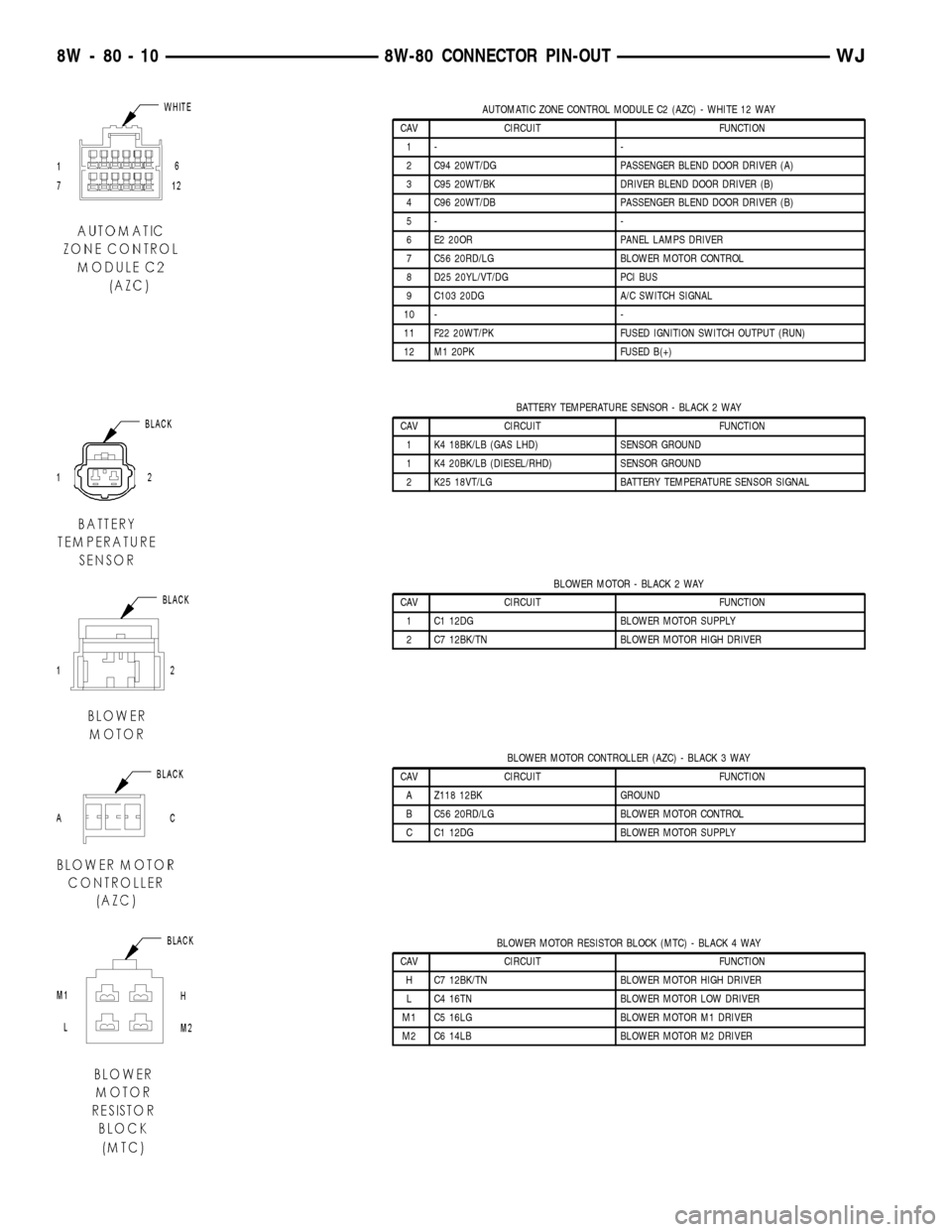
AUTOMATIC ZONE CONTROL MODULE C2 (AZC) - WHITE 12 WAY
CAV CIRCUIT FUNCTION
1- -
2 C94 20WT/DG PASSENGER BLEND DOOR DRIVER (A)
3 C95 20WT/BK DRIVER BLEND DOOR DRIVER (B)
4 C96 20WT/DB PASSENGER BLEND DOOR DRIVER (B)
5- -
6 E2 20OR PANEL LAMPS DRIVER
7 C56 20RD/LG BLOWER MOTOR CONTROL
8 D25 20YL/VT/DG PCI BUS
9 C103 20DG A/C SWITCH SIGNAL
10 - -
11 F22 20WT/PK FUSED IGNITION SWITCH OUTPUT (RUN)
12 M1 20PK FUSED B(+)
BATTERY TEMPERATURE SENSOR - BLACK 2 WAY
CAV CIRCUIT FUNCTION
1 K4 18BK/LB (GAS LHD) SENSOR GROUND
1 K4 20BK/LB (DIESEL/RHD) SENSOR GROUND
2 K25 18VT/LG BATTERY TEMPERATURE SENSOR SIGNAL
BLOWER MOTOR - BLACK 2 WAY
CAV CIRCUIT FUNCTION
1 C1 12DG BLOWER MOTOR SUPPLY
2 C7 12BK/TN BLOWER MOTOR HIGH DRIVER
BLOWER MOTOR CONTROLLER (AZC) - BLACK 3 WAY
CAV CIRCUIT FUNCTION
A Z118 12BK GROUND
B C56 20RD/LG BLOWER MOTOR CONTROL
C C1 12DG BLOWER MOTOR SUPPLY
BLOWER MOTOR RESISTOR BLOCK (MTC) - BLACK 4 WAY
CAV CIRCUIT FUNCTION
H C7 12BK/TN BLOWER MOTOR HIGH DRIVER
L C4 16TN BLOWER MOTOR LOW DRIVER
M1 C5 16LG BLOWER MOTOR M1 DRIVER
M2 C6 14LB BLOWER MOTOR M2 DRIVER
8W - 80 - 10 8W-80 CONNECTOR PIN-OUTWJ
Page 1060 of 2199
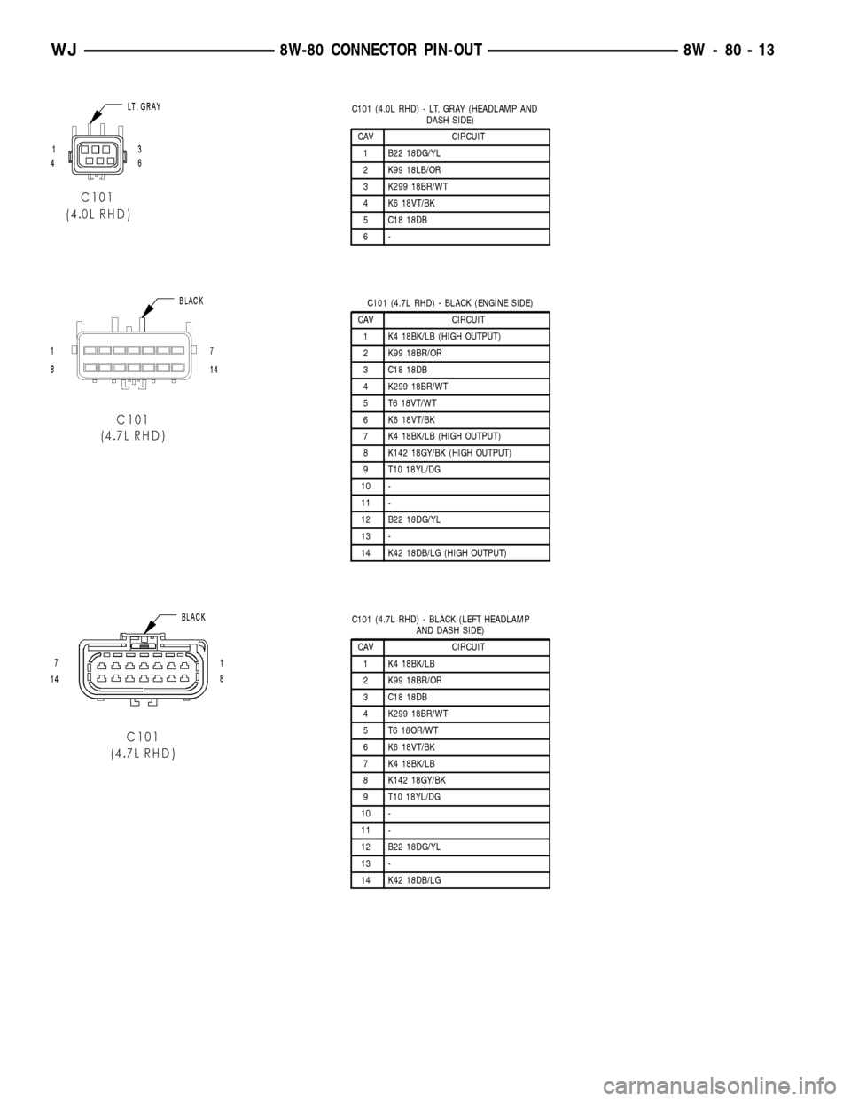
C101 (4.0L RHD) - LT. GRAY (HEADLAMP AND
DASH SIDE)
CAV CIRCUIT
1 B22 18DG/YL
2 K99 18LB/OR
3 K299 18BR/WT
4 K6 18VT/BK
5 C18 18DB
6-
C101 (4.7L RHD) - BLACK (ENGINE SIDE)
CAV CIRCUIT
1 K4 18BK/LB (HIGH OUTPUT)
2 K99 18BR/OR
3 C18 18DB
4 K299 18BR/WT
5 T6 18VT/WT
6 K6 18VT/BK
7 K4 18BK/LB (HIGH OUTPUT)
8 K142 18GY/BK (HIGH OUTPUT)
9 T10 18YL/DG
10 -
11 -
12 B22 18DG/YL
13 -
14 K42 18DB/LG (HIGH OUTPUT)
C101 (4.7L RHD) - BLACK (LEFT HEADLAMP
AND DASH SIDE)
CAV CIRCUIT
1 K4 18BK/LB
2 K99 18BR/OR
3 C18 18DB
4 K299 18BR/WT
5 T6 18OR/WT
6 K6 18VT/BK
7 K4 18BK/LB
8 K142 18GY/BK
9 T10 18YL/DG
10 -
11 -
12 B22 18DG/YL
13 -
14 K42 18DB/LG
WJ8W-80 CONNECTOR PIN-OUT 8W - 80 - 13
Page 1064 of 2199
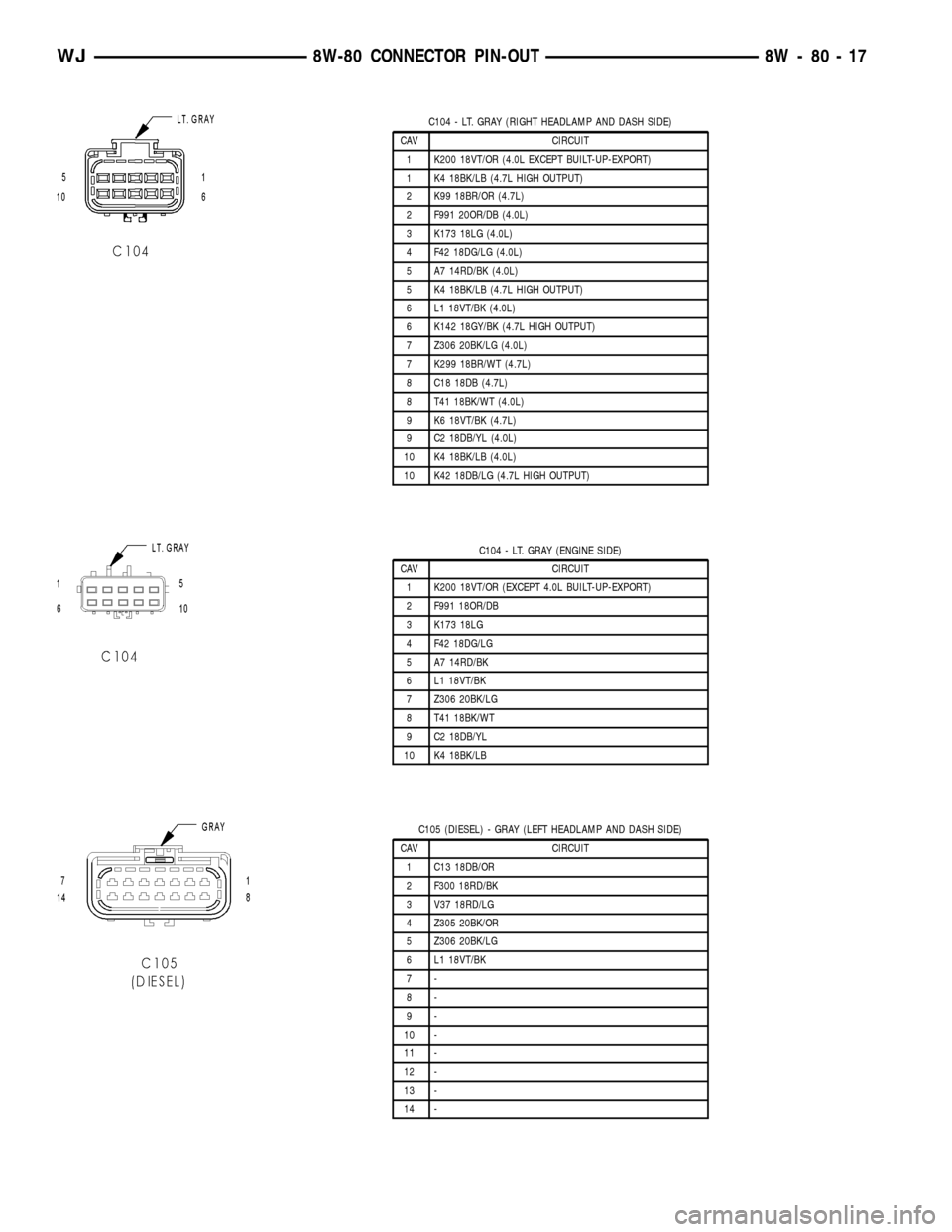
C104 - LT. GRAY (RIGHT HEADLAMP AND DASH SIDE)
CAV CIRCUIT
1 K200 18VT/OR (4.0L EXCEPT BUILT-UP-EXPORT)
1 K4 18BK/LB (4.7L HIGH OUTPUT)
2 K99 18BR/OR (4.7L)
2 F991 20OR/DB (4.0L)
3 K173 18LG (4.0L)
4 F42 18DG/LG (4.0L)
5 A7 14RD/BK (4.0L)
5 K4 18BK/LB (4.7L HIGH OUTPUT)
6 L1 18VT/BK (4.0L)
6 K142 18GY/BK (4.7L HIGH OUTPUT)
7 Z306 20BK/LG (4.0L)
7 K299 18BR/WT (4.7L)
8 C18 18DB (4.7L)
8 T41 18BK/WT (4.0L)
9 K6 18VT/BK (4.7L)
9 C2 18DB/YL (4.0L)
10 K4 18BK/LB (4.0L)
10 K42 18DB/LG (4.7L HIGH OUTPUT)
C104 - LT. GRAY (ENGINE SIDE)
CAV CIRCUIT
1 K200 18VT/OR (EXCEPT 4.0L BUILT-UP-EXPORT)
2 F991 18OR/DB
3 K173 18LG
4 F42 18DG/LG
5 A7 14RD/BK
6 L1 18VT/BK
7 Z306 20BK/LG
8 T41 18BK/WT
9 C2 18DB/YL
10 K4 18BK/LB
C105 (DIESEL) - GRAY (LEFT HEADLAMP AND DASH SIDE)
CAV CIRCUIT
1 C13 18DB/OR
2 F300 18RD/BK
3 V37 18RD/LG
4 Z305 20BK/OR
5 Z306 20BK/LG
6 L1 18VT/BK
7-
8-
9-
10 -
11 -
12 -
13 -
14 -
WJ8W-80 CONNECTOR PIN-OUT 8W - 80 - 17
Page 1107 of 2199
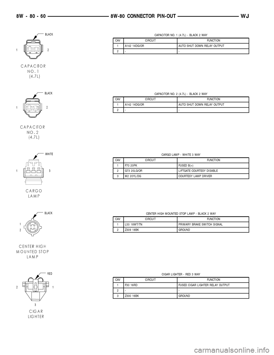
CAPACITOR NO. 1 (4.7L) - BLACK 2 WAY
CAV CIRCUIT FUNCTION
1 A142 14DG/OR AUTO SHUT DOWN RELAY OUTPUT
2- -
CAPACITOR NO. 2 (4.7L) - BLACK 2 WAY
CAV CIRCUIT FUNCTION
1 A142 14DG/OR AUTO SHUT DOWN RELAY OUTPUT
2- -
CARGO LAMP - WHITE 3 WAY
CAV CIRCUIT FUNCTION
1 F70 20PK FUSED B(+)
2 G73 20LG/OR LIFTGATE COURTESY DISABLE
3 M2 20YL/DG COURTESY LAMP DRIVER
CENTER HIGH MOUNTED STOP LAMP - BLACK 2 WAY
CAV CIRCUIT FUNCTION
1 L50 18WT/TN PRIMARY BRAKE SWITCH SIGNAL
2 Z309 18BK GROUND
CIGAR LIGHTER - RED 3 WAY
CAV CIRCUIT FUNCTION
1 F30 16RD FUSED CIGAR LIGHTER RELAY OUTPUT
2- -
3 Z300 16BK GROUND
8W - 80 - 60 8W-80 CONNECTOR PIN-OUTWJ
Page 1125 of 2199
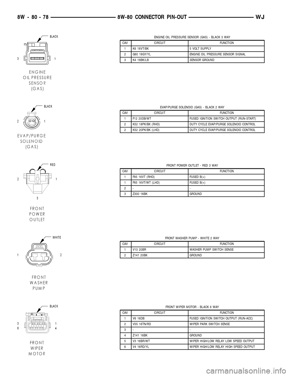
ENGINE OIL PRESSURE SENSOR (GAS) - BLACK 3 WAY
CAV CIRCUIT FUNCTION
1 K6 18VT/BK 5 VOLT SUPPLY
2 G60 18GY/YL ENGINE OIL PRESSURE SENSOR SIGNAL
3 K4 18BK/LB SENSOR GROUND
EVAP/PURGE SOLENOID (GAS) - BLACK 2 WAY
CAV CIRCUIT FUNCTION
1 F12 20DB/WT FUSED IGNITION SWITCH OUTPUT (RUN-START)
2 K52 18PK/BK (RHD) DUTY CYCLE EVAP/PURGE SOLENOID CONTROL
2 K52 20PK/BK (LHD) DUTY CYCLE EVAP/PURGE SOLENOID CONTROL
FRONT POWER OUTLET - RED 3 WAY
CAV CIRCUIT FUNCTION
1 F85 16VT (RHD) FUSED B(+)
1 F85 16VT/WT (LHD) FUSED B(+)
2- -
3 Z300 16BK GROUND
FRONT WASHER PUMP - WHITE 2 WAY
CAV CIRCUIT FUNCTION
1 V10 20BR WASHER PUMP SWITCH SENSE
2 Z141 20BK GROUND
FRONT WIPER MOTOR - BLACK 6 WAY
CAV CIRCUIT FUNCTION
1 V6 16DB FUSED IGNITION SWITCH OUTPUT (RUN-ACC)
2 V55 16TN/RD WIPER PARK SWITCH SENSE
3- -
4 Z141 16BK GROUND
5 V3 16BR/WT WIPER HIGH/LOW RELAY LOW SPEED OUTPUT
6 V4 16RD/YL WIPER HIGH/LOW RELAY HIGH SPEED OUTPUT
8W - 80 - 78 8W-80 CONNECTOR PIN-OUTWJ