Page 1978 of 2199

WEATHERSTRIP/SEALS
TABLE OF CONTENTS
page page
B-PILLAR DOOR SEAL
REMOVAL............................105
INSTALLATION........................105
COWL WEATHERSTRIP
REMOVAL............................106
INSTALLATION........................106
FRONT DOOR GLASS RUN WEATHERSTRIP
REMOVAL............................106
INSTALLATION........................106
FRONT DOOR INNER BELT WEATHERSTRIP
REMOVAL............................106
INSTALLATION........................107
FDR OUTER BELT WEATHERSTRIP
REMOVAL............................107
INSTALLATION........................107
FLIP-UP GLASS WEATHERSTRIP
REMOVAL............................107
INSTALLATION........................107
FRONT DOOR 2ND WEATHERSTRIP
REMOVAL............................107
INSTALLATION........................107
FRONT DOOR WEATHERSTRIP
REMOVAL............................108INSTALLATION........................108
HOOD SEAL
REMOVAL............................108
INSTALLATION........................108
LIFTGATE OPENING WEATHERSTRIP
REMOVAL............................109
INSTALLATION........................109
RDR INNER BELT WEATHERSTRIP
REMOVAL............................109
INSTALLATION........................109
RDR OUTER BELT WEATHERSTRIP
REMOVAL............................109
INSTALLATION........................109
RDR SECONDARY WEATHERSTRIP
REMOVAL............................110
INSTALLATION........................110
REAR DOOR WEATHERSTRIP
REMOVAL............................110
INSTALLATION........................110
ROOF RAIL WEATHERSTRIP / RETAINR
REMOVAL............................110
INSTALLATION........................110
B-PILLAR DOOR SEAL
REMOVAL
The B-pillar seal is attached to the rear door with
adhesive tape.
(1) Peel seal from the door (Fig. 1).
INSTALLATION
(1) Clean contact area with MopartSuper Kleen
or equivalent.
(2) Remove carrier from seal.
(3) Align seal on door and press into place.
Fig. 1 B-Pillar Seal
1 - B-PILLAR SEAL
WJWEATHERSTRIP/SEALS 23 - 105
Page 1981 of 2199

FRONT DOOR WEATHERSTRIP
REMOVAL
(1) Remove A-pillar trim (Refer to 23 - BODY/IN-
TERIOR/A-PILLAR TRIM - REMOVAL).
(2) Remove B-pillar upper trim (Refer to 23 -
BODY/INTERIOR/B-PILLAR UPPER TRIM -
REMOVAL).
(3) Remove B-pillar lower trim (Refer to 23 -
BODY/INTERIOR/B-PILLAR LOWER TRIM -
REMOVAL).
(4) Pull weatherstrip from door opening flange.
INSTALLATION
(1) Position weatherstrip at corners.
(2) Move upward and around edge of door opening
seating weatherstrip onto flange (Fig. 7).
(3) Engage connector plug with each end of weath-
erstrip at bottom of door opening.
(4) Install B-pillar lower trim (Refer to 23 - BODY/
INTERIOR/B-PILLAR LOWER TRIM - INSTALLA-
TION).
(5) Install B-pillar upper trim (Refer to 23 -
BODY/INTERIOR/B-PILLAR UPPER TRIM -
INSTALLATION).
(6) Install A-pillar trim (Refer to 23 - BODY/INTE-
RIOR/A-PILLAR TRIM - INSTALLATION).
HOOD SEAL
REMOVAL
(1) Raise hood.
(2) Pull hood seal from upper radiator crossmem-
ber.
(3) Separate seal from upper radiator crossmember
(Fig. 8).
INSTALLATION
(1) Position seal on upper radiator crossmember.
(2) Press seal onto upper radiator crossmember to
seat.
Fig. 7 Door Opening
1 - REAR DOOR OPENING WEATHERSTRIP
2 - FRONT DOOR OPENING WEATHERSTRIP
Fig. 8 Hood Seal
1 - HOOD SEAL
23 - 108 WEATHERSTRIP/SEALSWJ
Page 2027 of 2199

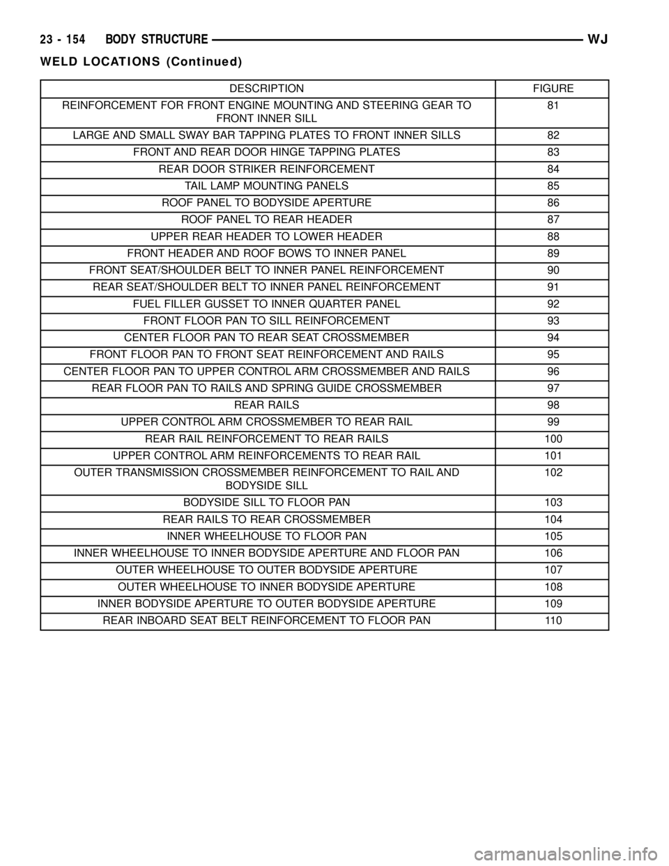
DESCRIPTION FIGURE
REINFORCEMENT FOR FRONT ENGINE MOUNTING AND STEERING GEAR TO
FRONT INNER SILL81
LARGE AND SMALL SWAY BAR TAPPING PLATES TO FRONT INNER SILLS 82
FRONT AND REAR DOOR HINGE TAPPING PLATES 83
REAR DOOR STRIKER REINFORCEMENT 84
TAIL LAMP MOUNTING PANELS 85
ROOF PANEL TO BODYSIDE APERTURE 86
ROOF PANEL TO REAR HEADER 87
UPPER REAR HEADER TO LOWER HEADER 88
FRONT HEADER AND ROOF BOWS TO INNER PANEL 89
FRONT SEAT/SHOULDER BELT TO INNER PANEL REINFORCEMENT 90
REAR SEAT/SHOULDER BELT TO INNER PANEL REINFORCEMENT 91
FUEL FILLER GUSSET TO INNER QUARTER PANEL 92
FRONT FLOOR PAN TO SILL REINFORCEMENT 93
CENTER FLOOR PAN TO REAR SEAT CROSSMEMBER 94
FRONT FLOOR PAN TO FRONT SEAT REINFORCEMENT AND RAILS 95
CENTER FLOOR PAN TO UPPER CONTROL ARM CROSSMEMBER AND RAILS 96
REAR FLOOR PAN TO RAILS AND SPRING GUIDE CROSSMEMBER 97
REAR RAILS 98
UPPER CONTROL ARM CROSSMEMBER TO REAR RAIL 99
REAR RAIL REINFORCEMENT TO REAR RAILS 100
UPPER CONTROL ARM REINFORCEMENTS TO REAR RAIL 101
OUTER TRANSMISSION CROSSMEMBER REINFORCEMENT TO RAIL AND
BODYSIDE SILL102
BODYSIDE SILL TO FLOOR PAN 103
REAR RAILS TO REAR CROSSMEMBER 104
INNER WHEELHOUSE TO FLOOR PAN 105
INNER WHEELHOUSE TO INNER BODYSIDE APERTURE AND FLOOR PAN 106
OUTER WHEELHOUSE TO OUTER BODYSIDE APERTURE 107
OUTER WHEELHOUSE TO INNER BODYSIDE APERTURE 108
INNER BODYSIDE APERTURE TO OUTER BODYSIDE APERTURE 109
REAR INBOARD SEAT BELT REINFORCEMENT TO FLOOR PAN 110
23 - 154 BODY STRUCTUREWJ
WELD LOCATIONS (Continued)
Page 2075 of 2199
Fig. 108 OUTER WHEELHOUSE TO INNER BODYSIDE APERTURE
Fig. 109 INNER BODYSIDE APERTURE TO OUTER BODYSIDE APERTURE
23 - 202 BODY STRUCTUREWJ
WELD LOCATIONS (Continued)
Page 2158 of 2199

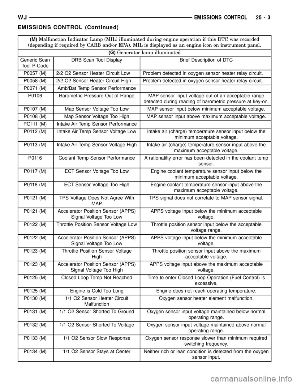
(M)Malfunction Indicator Lamp (MIL) illuminated during engine operation if this DTC was recorded
(depending if required by CARB and/or EPA). MIL is displayed as an engine icon on instrument panel.
(G)Generator lamp illuminated
Generic Scan
Tool P-CodeDRB Scan Tool Display Brief Description of DTC
P0057 (M) 2/2 O2 Sensor Heater Circuit Low Problem detected in oxygen sensor heater relay circuit.
P0058 (M) 2/2 O2 Sensor Heater Circuit High Problem detected in oxygen sensor heater relay circuit.
P0071 (M) Amb/Bat Temp Sensor Performance
P0106 Barometric Pressure Out of Range MAP sensor input voltage out of an acceptable range
detected during reading of barometric pressure at key-on.
P0107 (M) Map Sensor Voltage Too Low MAP sensor input below minimum acceptable voltage.
P0108 (M) Map Sensor Voltage Too High MAP sensor input above maximum acceptable voltage.
PO111 (M) Intake Air Temp Sensor Performance
P0112 (M) Intake Air Temp Sensor Voltage Low Intake air (charge) temperature sensor input below the
minimum acceptable voltage.
P0113 (M) Intake Air Temp Sensor Voltage High Intake air (charge) temperature sensor input above the
maximum acceptable voltage.
P0116 Coolant Temp Sensor Performance A rationatilty error has been detected in the coolant temp
sensor.
P0117 (M) ECT Sensor Voltage Too Low Engine coolant temperature sensor input below the
minimum acceptable voltage.
P0118 (M) ECT Sensor Voltage Too High Engine coolant temperature sensor input above the
maximum acceptable voltage.
P0121 (M) TPS Voltage Does Not Agree With
MAPTPS signal does not correlate to MAP sensor signal.
P0121 (M) Accelerator Position Sensor (APPS)
Signal Voltage Too LowAPPS voltage input below the minimum acceptable
voltage.
P0122 (M) Throttle Position Sensor Voltage Low Throttle position sensor input below the acceptable
voltage range.
P0122 (M) Accelerator Position Sensor (APPS)
Signal Voltage Too LowAPPS voltage input below the minimum acceptable
voltage.
P0123 (M) Throttle Position Sensor Voltage
HighThrottle position sensor input above the maximum
acceptable voltage.
P0123 (M) Accelerator Position Sensor (APPS)
Signal Voltage Too HighAPPS voltage input above the maximum acceptable
voltage.
P0125 (M) Closed Loop Temp Not Reached Time to enter Closed Loop Operation (Fuel Control) is
excessive.
P0125 (M) Engine is Cold Too Long Engine does not reach operating temperature.
P0130 (M) 1/1 O2 Sensor Heater Circuit
MalfunctionOxygen sensor heater element malfunction.
P0131 (M) 1/1 O2 Sensor Shorted To Ground Oxygen sensor input voltage maintained below normal
operating range.
P0132 (M) 1/1 O2 Sensor Shorted To Voltage Oxygen sensor input voltage maintained above normal
operating range.
P0133 (M) 1/1 O2 Sensor Slow Response Oxygen sensor response slower than minimum required
switching frequency.
P0134 (M) 1/1 O2 Sensor Stays at Center Neither rich or lean condition is detected from the oxygen
sensor input.
WJEMISSIONS CONTROL 25 - 3
EMISSIONS CONTROL (Continued)