2002 JEEP GRAND CHEROKEE coolant level
[x] Cancel search: coolant levelPage 1179 of 2199
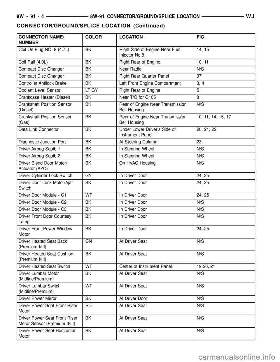
CONNECTOR NAME/
NUMBERCOLOR LOCATION FIG.
Coil On Plug NO. 8 (4.7L) BK Right Side of Engine Near Fuel
Injector No.814, 15
Coil Rail (4.0L) BK Right Rear of Engine 10, 11
Compact Disc Changer BK Near Radio N/S
Compact Disc Changer BK Right Rear Quarter Panel 37
Controller Antilock Brake BK Left Front Engine Compartment 3, 4
Coolant Level Sensor LT GY Right Rear of Engine 5
Crankcase Heater (Diesel) BK Near T/O for G105 8
Crankshaft Position Sensor
(Diesel)BK Rear of Engine Near Transmission
Bell HousingN/S
Crankshaft Position Sensor
(Gas)BK Rear of Engine Near Transmission
Bell Housing10, 11, 14, 15, 17
Data Link Connector BK Under Lower Driver's Side of
Instrument Panel20, 21, 22
Diagnostic Junction Port BK At Steering Column 23
Driver Airbag Squib 1 BK In Steering Wheel N/S
Driver Airbag Squib 2 BK In Steering Wheel N/S
Driver Blend Door Motor/
Actuator (AZC)BK On HVAC Housing N/S
Driver Cylinder Lock Switch GY In Driver Door 24, 25
Driver Door Lock Motor/Ajar
SwitchBK In Driver Door 24, 25
Driver Door Module - C1 WT In Driver Door 24, 25
Driver Door Module - C2 BK In Driver Door N/S
Driver Door Module - C3 BK In Driver Door N/S
Driver Front Door Courtesy
LampBK In Driver Door N/S
Driver Front Power Window
MotorBK In Driver Door 24, 25
Driver Heated Seat Back
(Premium I/III)GN At Driver Seat N/S
Driver Heated Seat Cushion
(Premium I/III)BK At Driver Seat N/S
Driver Heated Seat Switch WT Center of Instrument Panel 19 20, 21
Driver Lumbar Motor
(Midline/Premium)BK At Driver Seat N/S
Driver Lumbar Switch
(Midline/Premium)WT At Driver Seat N/S
Driver Power Mirror BK At Driver Door N/S
Driver Power Seat Front Riser
MotorRD At Driver Seat N/S
Driver Power Seat Front Riser
Motor Sensor (Premium II/III)BK At Driver Seat N/S
Driver Power Seat Horizontal
MotorBK At Driver Seat N/S
8W - 91 - 4 8W-91 CONNECTOR/GROUND/SPLICE LOCATIONWJ
CONNECTOR/GROUND/SPLICE LOCATION (Continued)
Page 1188 of 2199
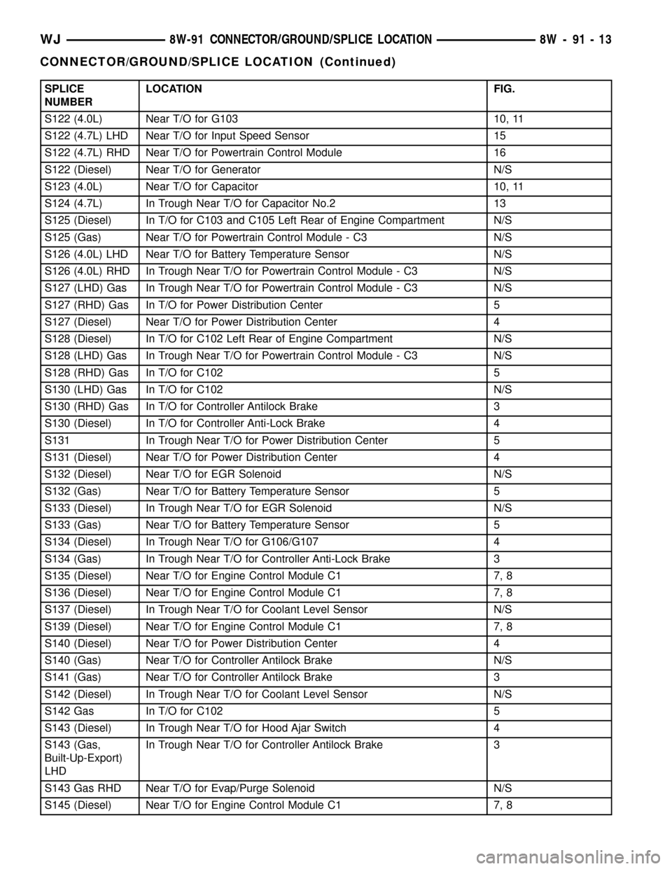
SPLICE
NUMBERLOCATION FIG.
S122 (4.0L) Near T/O for G103 10, 11
S122 (4.7L) LHD Near T/O for Input Speed Sensor 15
S122 (4.7L) RHD Near T/O for Powertrain Control Module 16
S122 (Diesel) Near T/O for Generator N/S
S123 (4.0L) Near T/O for Capacitor 10, 11
S124 (4.7L) In Trough Near T/O for Capacitor No.2 13
S125 (Diesel) In T/O for C103 and C105 Left Rear of Engine Compartment N/S
S125 (Gas) Near T/O for Powertrain Control Module - C3 N/S
S126 (4.0L) LHD Near T/O for Battery Temperature Sensor N/S
S126 (4.0L) RHD In Trough Near T/O for Powertrain Control Module - C3 N/S
S127 (LHD) Gas In Trough Near T/O for Powertrain Control Module - C3 N/S
S127 (RHD) Gas In T/O for Power Distribution Center 5
S127 (Diesel) Near T/O for Power Distribution Center 4
S128 (Diesel) In T/O for C102 Left Rear of Engine Compartment N/S
S128 (LHD) Gas In Trough Near T/O for Powertrain Control Module - C3 N/S
S128 (RHD) Gas In T/O for C102 5
S130 (LHD) Gas In T/O for C102 N/S
S130 (RHD) Gas In T/O for Controller Antilock Brake 3
S130 (Diesel) In T/O for Controller Anti-Lock Brake 4
S131 In Trough Near T/O for Power Distribution Center 5
S131 (Diesel) Near T/O for Power Distribution Center 4
S132 (Diesel) Near T/O for EGR Solenoid N/S
S132 (Gas) Near T/O for Battery Temperature Sensor 5
S133 (Diesel) In Trough Near T/O for EGR Solenoid N/S
S133 (Gas) Near T/O for Battery Temperature Sensor 5
S134 (Diesel) In Trough Near T/O for G106/G107 4
S134 (Gas) In Trough Near T/O for Controller Anti-Lock Brake 3
S135 (Diesel) Near T/O for Engine Control Module C1 7, 8
S136 (Diesel) Near T/O for Engine Control Module C1 7, 8
S137 (Diesel) In Trough Near T/O for Coolant Level Sensor N/S
S139 (Diesel) Near T/O for Engine Control Module C1 7, 8
S140 (Diesel) Near T/O for Power Distribution Center 4
S140 (Gas) Near T/O for Controller Antilock Brake N/S
S141 (Gas) Near T/O for Controller Antilock Brake 3
S142 (Diesel) In Trough Near T/O for Coolant Level Sensor N/S
S142 Gas In T/O for C102 5
S143 (Diesel) In Trough Near T/O for Hood Ajar Switch 4
S143 (Gas,
Built-Up-Export)
LHDIn Trough Near T/O for Controller Antilock Brake 3
S143 Gas RHD Near T/O for Evap/Purge Solenoid N/S
S145 (Diesel) Near T/O for Engine Control Module C1 7, 8
WJ8W-91 CONNECTOR/GROUND/SPLICE LOCATION 8W - 91 - 13
CONNECTOR/GROUND/SPLICE LOCATION (Continued)
Page 1251 of 2199
DIAGNOSIS AND TESTINGÐCYLINDER
COMPRESSION PRESSURE
The results of a cylinder compression pressure test
can be utilized to diagnose several engine malfunc-
tions.
Ensure the battery is completely charged and the
engine starter motor is in good operating condition.
Otherwise, the indicated compression pressures may
not be valid for diagnosis purposes.
(1) Clean the spark plug recesses with compressed
air.
(2) Remove the spark plugs (Refer to 8 - ELEC-
TRICAL/IGNITION CONTROL/SPARK PLUG -
REMOVAL).
(3) Secure the throttle in the wide-open position.
(4) Disconnect the ignition coil.
(5) Insert a compression pressure gauge and rotate
the engine with the engine starter motor for three
revolutions.
(6) Record the compression pressure on the third
revolution. Continue the test for the remaining cylin-
ders.
(Refer to 9 - ENGINE - SPECIFICATIONS) for the
correct engine compression pressures.
DIAGNOSIS AND TESTING - CYLINDER
COMBUSTION PRESSURE LEAKAGE
The combustion pressure leakage test provides an
accurate means for determining engine condition.
Combustion pressure leakage testing will detect:
²Exhaust and intake valve leaks (improper seat-
ing)
²Leaks between adjacent cylinders or into water
jacket²Any causes for combustion/compression pressure
loss
WARNING: DO NOT REMOVE THE RADIATOR CAP
WITH THE SYSTEM HOT AND UNDER PRESSURE.
SERIOUS BURNS FROM HOT COOLANT CAN
OCCUR.
Check the coolant level and fill as required. DO
NOT install the radiator cap.
Start and operate the engine until it attains nor-
mal operating temperature, then turn OFF the
engine.
Remove the spark plugs.
Remove the oil filler cap.
Remove the air cleaner.
Calibrate the tester according to the manufactur-
er's instructions. The shop air source for testing
should maintain 483 kPa (70 psi) minimum, 1,379
kPa (200 psi) maximum and 552 kPa (80 psi) recom-
mended.
Perform the test procedure on each cylinder accord-
ing to the tester manufacturer's instructions. While
testing, listen for pressurized air escaping through
the throttle body, tailpipe or oil filler cap opening.
Check for bubbles in the radiator coolant.
All gauge pressure indications should be equal,
with no more than 25% leakage.
FOR EXAMPLE:At 552 kPa (80 psi) input pres-
sure, a minimum of 414 kPa (60 psi) should be main-
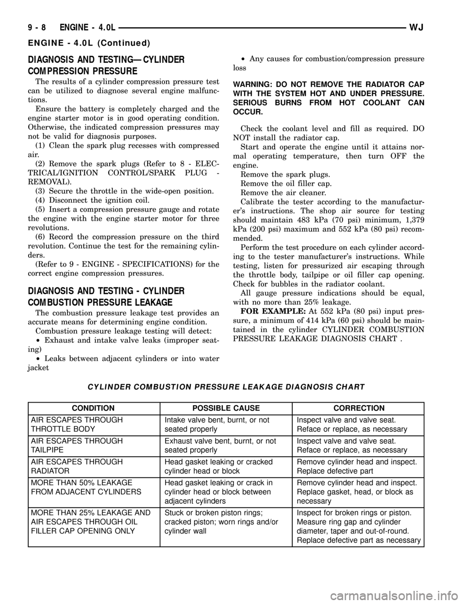
tained in the cylinder CYLINDER COMBUSTION
PRESSURE LEAKAGE DIAGNOSIS CHART .
CYLINDER COMBUSTION PRESSURE LEAKAGE DIAGNOSIS CHART
CONDITION POSSIBLE CAUSE CORRECTION
AIR ESCAPES THROUGH
THROTTLE BODYIntake valve bent, burnt, or not
seated properlyInspect valve and valve seat.
Reface or replace, as necessary
AIR ESCAPES THROUGH
TAILPIPEExhaust valve bent, burnt, or not
seated properlyInspect valve and valve seat.
Reface or replace, as necessary
AIR ESCAPES THROUGH
RADIATORHead gasket leaking or cracked
cylinder head or blockRemove cylinder head and inspect.
Replace defective part
MORE THAN 50% LEAKAGE
FROM ADJACENT CYLINDERSHead gasket leaking or crack in
cylinder head or block between
adjacent cylindersRemove cylinder head and inspect.
Replace gasket, head, or block as
necessary
MORE THAN 25% LEAKAGE AND
AIR ESCAPES THROUGH OIL
FILLER CAP OPENING ONLYStuck or broken piston rings;
cracked piston; worn rings and/or
cylinder wallInspect for broken rings or piston.
Measure ring gap and cylinder
diameter, taper and out-of-round.
Replace defective part as necessary
9 - 8 ENGINE - 4.0LWJ
ENGINE - 4.0L (Continued)
Page 1265 of 2199
(12) Install the push rods, rocker arms, pivots and
bridges in the order they were removed (Refer to 9 -
ENGINE/CYLINDER HEAD/ROCKER ARM /
ADJUSTER ASSY - INSTALLATION).
(13) Install the engine cylinder head cover (Refer
to 9 - ENGINE/CYLINDER HEAD/CYLINDER
HEAD COVER(S) - INSTALLATION).
(14) Attach the air conditioner compressor mount-
ing bracket to the engine cylinder head and block.
Tighten the bolts to 40 N´m (30 ft. lbs.) torque.
(15) Attach the air conditioning compressor to the
bracket. Tighten the bolts to 27 N´m (20 ft. lbs.)
torque.
CAUTION: The serpentine drive belt must be routed
correctly. Incorrect routing can cause the water
pump to turn in the opposite direction causing the
engine to overheat.
(16) Install the serpentine drive belt. (Refer to 7 -
COOLING/ACCESSORY DRIVE/DRIVE BELTS -
INSTALLATION).
(17) Install the air cleaner and ducting.
(18) Connect the hoses to the engine thermostat
housing and fill the cooling system to the specified
level (Refer to 7 - COOLING - STANDARD PROCE-
DURE).
(19) The automatic transmission throttle linkage
and cable must be adjusted after completing the
engine cylinder head installation (Refer to 21 -
TRANSMISSION/TRANSAXLE/AUTOMATIC - AW4/
THROTTLE VALVE CABLE - ADJUSTMENTS).
(20) Install the temperature sending unit and con-
nect the wire connector.
(21) If equipped with air conditioning, install A/C
compressor (Refer to 24 - HEATING & AIR CONDI-
TIONING/PLUMBING/A/C COMPRESSOR -
INSTALLATION) and charge A/C system (Refer to 24
- HEATING & AIR CONDITIONING/PLUMBING -
STANDARD PROCEDURE).
(22) Connect negative cable to battery.
WARNING: USE EXTREME CAUTION WHEN THE
ENGINE IS OPERATING. DO NOT STAND IN DIRECT
LINE WITH THE FAN. DO NOT PUT HANDS NEAR
THE PULLEYS, BELTS OR FAN. DO NOT WEAR
LOOSE CLOTHING.
(23) Operate the engine with the radiator cap off.
Inspect for leaks and continue operating the engine
until the engine thermostat opens. Add coolant, if
required.CYLINDER HEAD COVER(S)
DESCRIPTION
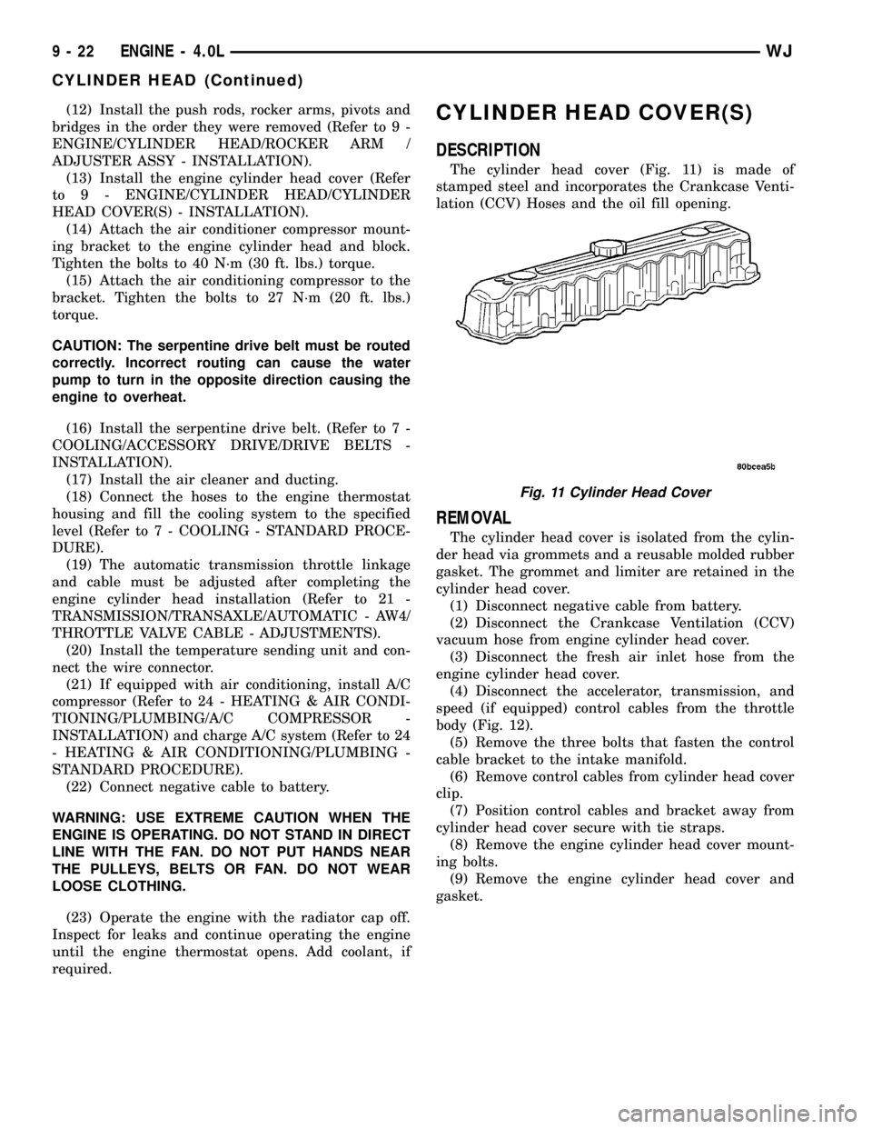
The cylinder head cover (Fig. 11) is made of
stamped steel and incorporates the Crankcase Venti-
lation (CCV) Hoses and the oil fill opening.
REMOVAL
The cylinder head cover is isolated from the cylin-
der head via grommets and a reusable molded rubber
gasket. The grommet and limiter are retained in the
cylinder head cover.
(1) Disconnect negative cable from battery.
(2) Disconnect the Crankcase Ventilation (CCV)
vacuum hose from engine cylinder head cover.
(3) Disconnect the fresh air inlet hose from the
engine cylinder head cover.
(4) Disconnect the accelerator, transmission, and
speed (if equipped) control cables from the throttle
body (Fig. 12).
(5) Remove the three bolts that fasten the control
cable bracket to the intake manifold.
(6) Remove control cables from cylinder head cover
clip.
(7) Position control cables and bracket away from
cylinder head cover secure with tie straps.
(8) Remove the engine cylinder head cover mount-
ing bolts.
(9) Remove the engine cylinder head cover and
gasket.
Fig. 11 Cylinder Head Cover
9 - 22 ENGINE - 4.0LWJ
CYLINDER HEAD (Continued)
Page 1300 of 2199

INSTALLATION
A gear-type oil pump is mounted at the underside
of the cylinder block opposite the No.4 main bearing.
(1) Install the oil pump on the cylinder block using
a replacement gasket. Tighten the bolts to 23 N´m
(17 ft. lbs.) torque.
(2) Install the oil pan (Refer to 9 - ENGINE/LU-
BRICATION/OIL PAN - INSTALLATION).
(3) Fill the oil pan with oil to the specified level.
INTAKE MANIFOLD
DESCRIPTION
The intake manifold (Fig. 83) is made of cast alu-
minum and uses eleven bolts to mount to the cylin-
der head. This mounting style improves sealing and
reduces the chance of leaks.
DIAGNOSIS AND TESTING - INTAKE
MANIFOLD LEAKAGE
An intake manifold air leak is characterized by
lower than normal manifold vacuum. Also, one or
more cylinders may not be functioning.
WARNING: USE EXTREME CAUTION WHEN THE
ENGINE IS OPERATING. DO NOT STAND IN A
DIRECT LINE WITH THE FAN. DO NOT PUT YOUR
HANDS NEAR THE PULLEYS, BELTS OR THE FAN.
DO NOT WEAR LOOSE CLOTHING.
(1) Start the engine.
(2) Spray a small stream of water at the suspected
leak area.
(3) If a change in RPM is observed the area of the
suspected leak has been found.
(4) Repair as required.
REMOVAL
NOTE: THE ENGINE INTAKE AND EXHAUST MANI-
FOLD MUST BE REMOVED AND INSTALLED
TOGETHER. THE MANIFOLDS USE A COMMON
GASKET AT THE CYLINDER HEAD.
(1) Disconnect the battery negative cable.
(2) Remove air cleaner inlet hose from the resona-
tor assembly.
(3) Remove the air cleaner assembly.
(4) Remove the throttle cable, vehicle speed control
cable (if equipped) and the transmission line pres-
sure cable (Refer to 21 - TRANSMISSION/TRANS-
AXLE/AUTOMATIC - AW4/THROTTLE VALVE
CABLE - REMOVAL).
(5) Disconnect the following electrical connections
and secure their harness out of the way:
²Throttle Position Sensor
²Idle Air Control Motor
²Coolant Temperature Sensor (at thermostat
housing)
²Intake Air Temperature Sensor
²Oxygen Sensor
²Crank Position Sensor
²Six (6) Fuel Injector Connectors
²Manifold Absolute Pressure (MAP) Sensor.
(6) Disconnect HVAC, and Brake Booster vacuum
supply hoses at the intake manifold.
(7) Perform the fuel pressure release procedure.
(Refer to 14 - FUEL SYSTEM/FUEL DELIVERY -
STANDARD PROCEDURE).
(8) Disconnect and remove the fuel system supply
line from the fuel rail assembly.
(9) Remove the accessory drive belt (Refer to 7 -
COOLING/ACCESSORY DRIVE/DRIVE BELTS -
REMOVAL).
(10) Remove the power steering pump from the
intake manifold and set aside.
(11) Raise the vehicle.
(12) Disconnect the exhaust pipes from the engine
exhaust manifolds.
(13) Lower the vehicle.
(14) Remove the intake manifold and exhaust
manifold bolts and manifolds (Fig. 84).
INSTALLATION
If the manifold is being replaced, ensure all the fit-
ting, etc. are transferred to the replacement mani-
fold.
(1) Install a new engine exhaust/intake manifold
gasket over the alignment dowels on the cylinder
head.
(2) Position the engine exhaust manifolds to the
cylinder head. Install fastener Number 3 and finger
tighten at this time (Fig. 84).
Fig. 83 Intake Manifold 4.0L Engine
WJENGINE - 4.0L 9 - 57
OIL PUMP (Continued)
Page 1312 of 2199
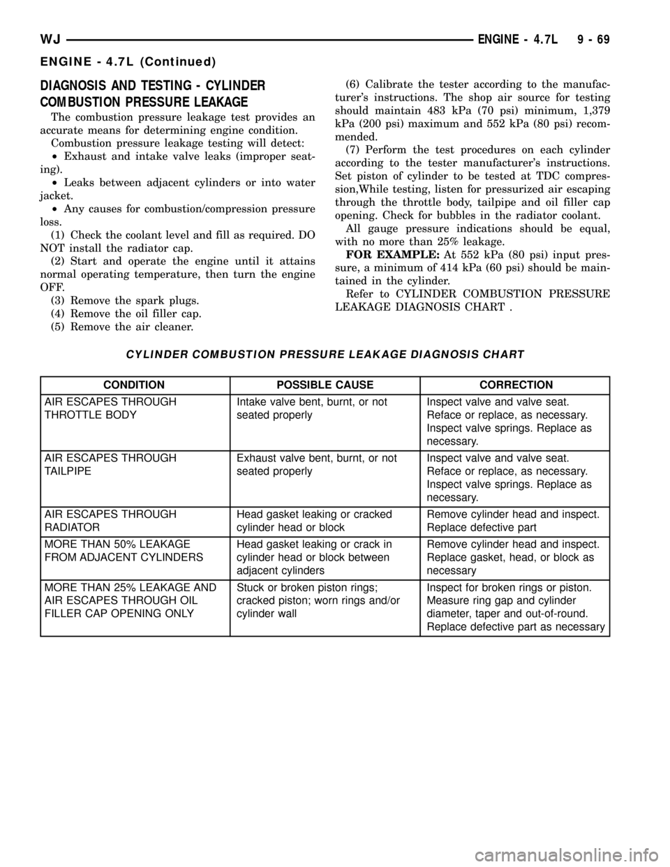
DIAGNOSIS AND TESTING - CYLINDER
COMBUSTION PRESSURE LEAKAGE
The combustion pressure leakage test provides an
accurate means for determining engine condition.
Combustion pressure leakage testing will detect:
²Exhaust and intake valve leaks (improper seat-
ing).
²Leaks between adjacent cylinders or into water
jacket.
²Any causes for combustion/compression pressure
loss.
(1) Check the coolant level and fill as required. DO
NOT install the radiator cap.
(2) Start and operate the engine until it attains
normal operating temperature, then turn the engine
OFF.
(3) Remove the spark plugs.
(4) Remove the oil filler cap.
(5) Remove the air cleaner.(6) Calibrate the tester according to the manufac-
turer's instructions. The shop air source for testing
should maintain 483 kPa (70 psi) minimum, 1,379
kPa (200 psi) maximum and 552 kPa (80 psi) recom-
mended.
(7) Perform the test procedures on each cylinder
according to the tester manufacturer's instructions.
Set piston of cylinder to be tested at TDC compres-
sion,While testing, listen for pressurized air escaping
through the throttle body, tailpipe and oil filler cap
opening. Check for bubbles in the radiator coolant.
All gauge pressure indications should be equal,
with no more than 25% leakage.
FOR EXAMPLE:At 552 kPa (80 psi) input pres-
sure, a minimum of 414 kPa (60 psi) should be main-
tained in the cylinder.
Refer to CYLINDER COMBUSTION PRESSURE
LEAKAGE DIAGNOSIS CHART .
CYLINDER COMBUSTION PRESSURE LEAKAGE DIAGNOSIS CHART
CONDITION POSSIBLE CAUSE CORRECTION
AIR ESCAPES THROUGH
THROTTLE BODYIntake valve bent, burnt, or not
seated properlyInspect valve and valve seat.
Reface or replace, as necessary.
Inspect valve springs. Replace as
necessary.
AIR ESCAPES THROUGH
TAILPIPEExhaust valve bent, burnt, or not
seated properlyInspect valve and valve seat.
Reface or replace, as necessary.
Inspect valve springs. Replace as
necessary.
AIR ESCAPES THROUGH
RADIATORHead gasket leaking or cracked
cylinder head or blockRemove cylinder head and inspect.
Replace defective part
MORE THAN 50% LEAKAGE
FROM ADJACENT CYLINDERSHead gasket leaking or crack in
cylinder head or block between
adjacent cylindersRemove cylinder head and inspect.
Replace gasket, head, or block as
necessary
MORE THAN 25% LEAKAGE AND
AIR ESCAPES THROUGH OIL
FILLER CAP OPENING ONLYStuck or broken piston rings;
cracked piston; worn rings and/or
cylinder wallInspect for broken rings or piston.
Measure ring gap and cylinder
diameter, taper and out-of-round.
Replace defective part as necessary
WJENGINE - 4.7L 9 - 69
ENGINE - 4.7L (Continued)
Page 1341 of 2199
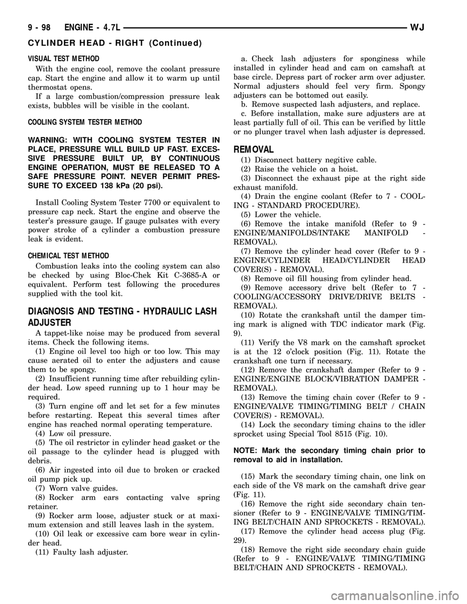
VISUAL TEST METHOD
With the engine cool, remove the coolant pressure
cap. Start the engine and allow it to warm up until
thermostat opens.
If a large combustion/compression pressure leak
exists, bubbles will be visible in the coolant.
COOLING SYSTEM TESTER METHOD
WARNING: WITH COOLING SYSTEM TESTER IN
PLACE, PRESSURE WILL BUILD UP FAST. EXCES-
SIVE PRESSURE BUILT UP, BY CONTINUOUS
ENGINE OPERATION, MUST BE RELEASED TO A
SAFE PRESSURE POINT. NEVER PERMIT PRES-
SURE TO EXCEED 138 kPa (20 psi).
Install Cooling System Tester 7700 or equivalent to
pressure cap neck. Start the engine and observe the
tester's pressure gauge. If gauge pulsates with every
power stroke of a cylinder a combustion pressure
leak is evident.
CHEMICAL TEST METHOD
Combustion leaks into the cooling system can also
be checked by using Bloc-Chek Kit C-3685-A or
equivalent. Perform test following the procedures
supplied with the tool kit.
DIAGNOSIS AND TESTING - HYDRAULIC LASH
ADJUSTER
A tappet-like noise may be produced from several
items. Check the following items.
(1) Engine oil level too high or too low. This may
cause aerated oil to enter the adjusters and cause
them to be spongy.
(2) Insufficient running time after rebuilding cylin-
der head. Low speed running up to 1 hour may be
required.
(3) Turn engine off and let set for a few minutes
before restarting. Repeat this several times after
engine has reached normal operating temperature.
(4) Low oil pressure.
(5) The oil restrictor in cylinder head gasket or the
oil passage to the cylinder head is plugged with
debris.
(6) Air ingested into oil due to broken or cracked
oil pump pick up.
(7) Worn valve guides.
(8) Rocker arm ears contacting valve spring
retainer.
(9) Rocker arm loose, adjuster stuck or at maxi-
mum extension and still leaves lash in the system.
(10) Oil leak or excessive cam bore wear in cylin-
der head.
(11) Faulty lash adjuster.a. Check lash adjusters for sponginess while
installed in cylinder head and cam on camshaft at
base circle. Depress part of rocker arm over adjuster.
Normal adjusters should feel very firm. Spongy
adjusters can be bottomed out easily.
b. Remove suspected lash adjusters, and replace.
c. Before installation, make sure adjusters are at
least partially full of oil. This can be verified by little
or no plunger travel when lash adjuster is depressed.
REMOVAL
(1) Disconnect battery negitive cable.
(2) Raise the vehicle on a hoist.
(3) Disconnect the exhaust pipe at the right side
exhaust manifold.
(4) Drain the engine coolant (Refer to 7 - COOL-
ING - STANDARD PROCEDURE).
(5) Lower the vehicle.
(6) Remove the intake manifold (Refer to 9 -
ENGINE/MANIFOLDS/INTAKE MANIFOLD -
REMOVAL).
(7) Remove the cylinder head cover (Refer to 9 -
ENGINE/CYLINDER HEAD/CYLINDER HEAD
COVER(S) - REMOVAL).
(8) Remove oil fill housing from cylinder head.
(9) Remove accessory drive belt (Refer to 7 -
COOLING/ACCESSORY DRIVE/DRIVE BELTS -
REMOVAL).
(10) Rotate the crankshaft until the damper tim-
ing mark is aligned with TDC indicator mark (Fig.
9).
(11) Verify the V8 mark on the camshaft sprocket
is at the 12 o'clock position (Fig. 11). Rotate the
crankshaft one turn if necessary.
(12) Remove the crankshaft damper (Refer to 9 -
ENGINE/ENGINE BLOCK/VIBRATION DAMPER -
REMOVAL).
(13) Remove the timing chain cover (Refer to 9 -
ENGINE/VALVE TIMING/TIMING BELT / CHAIN
COVER(S) - REMOVAL).
(14) Lock the secondary timing chains to the idler
sprocket using Special Tool 8515 (Fig. 10).
NOTE: Mark the secondary timing chain prior to
removal to aid in installation.
(15) Mark the secondary timing chain, one link on
each side of the V8 mark on the camshaft drive gear
(Fig. 11).
(16) Remove the right side secondary chain ten-
sioner (Refer to 9 - ENGINE/VALVE TIMING/TIM-
ING BELT/CHAIN AND SPROCKETS - REMOVAL).
(17) Remove the cylinder head access plug (Fig.
29).
(18) Remove the right side secondary chain guide
(Refer to 9 - ENGINE/VALVE TIMING/TIMING
BELT/CHAIN AND SPROCKETS - REMOVAL).
9 - 98 ENGINE - 4.7LWJ
CYLINDER HEAD - RIGHT (Continued)
Page 1380 of 2199
(6) Remove accessory drive belt (Refer to 7 -
COOLING/ACCESSORY DRIVE/DRIVE BELTS -
REMOVAL).
(7) Disconnect generator electrical connections.
(8) Unbolt the generator and move it away from
the intake manifold for clearance.
(9) Disconnect air conditioning compressor electri-
cal connections.
(10) Unbolt the air conditioning compressor and
move it away from the intake manifold for clearance.
(11) Disconnect left and right radio suppressor
straps.
(12) Disconnect and remove ignition coil towers
(Refer to 8 - ELECTRICAL/IGNITION CONTROL/
IGNITION COIL - REMOVAL).
(13) Remove top oil dipstick tube retaining bolt
and ground strap.
(14) Bleed pressure from fuel system (Refer to 14 -
FUEL SYSTEM/FUEL DELIVERY - STANDARD
PROCEDURE).
(15) Remove fuel rail (Refer to 14 - FUEL SYS-
TEM/FUEL DELIVERY/FUEL RAIL - REMOVAL).
(16) Remove throttle body assembly and mounting
bracket.
(17) Drain cooling system below coolant tempera-
ture level (Refer to 7 - COOLING - STANDARD
PROCEDURE).
(18) Remove coolant temperature sensor (Refer to
7 - COOLING/ENGINE/ENGINE COOLANT TEMP
SENSOR - REMOVAL).
(19) Remove cowl to hood seal. (Refer to 23 -
BODY/WEATHERSTRIP/SEALS/COWL WEATHER-
STRIP - REMOVAL).
(20) Remove right side engine lifting stud.
(21) Remove intake manifold retaining fasteners,
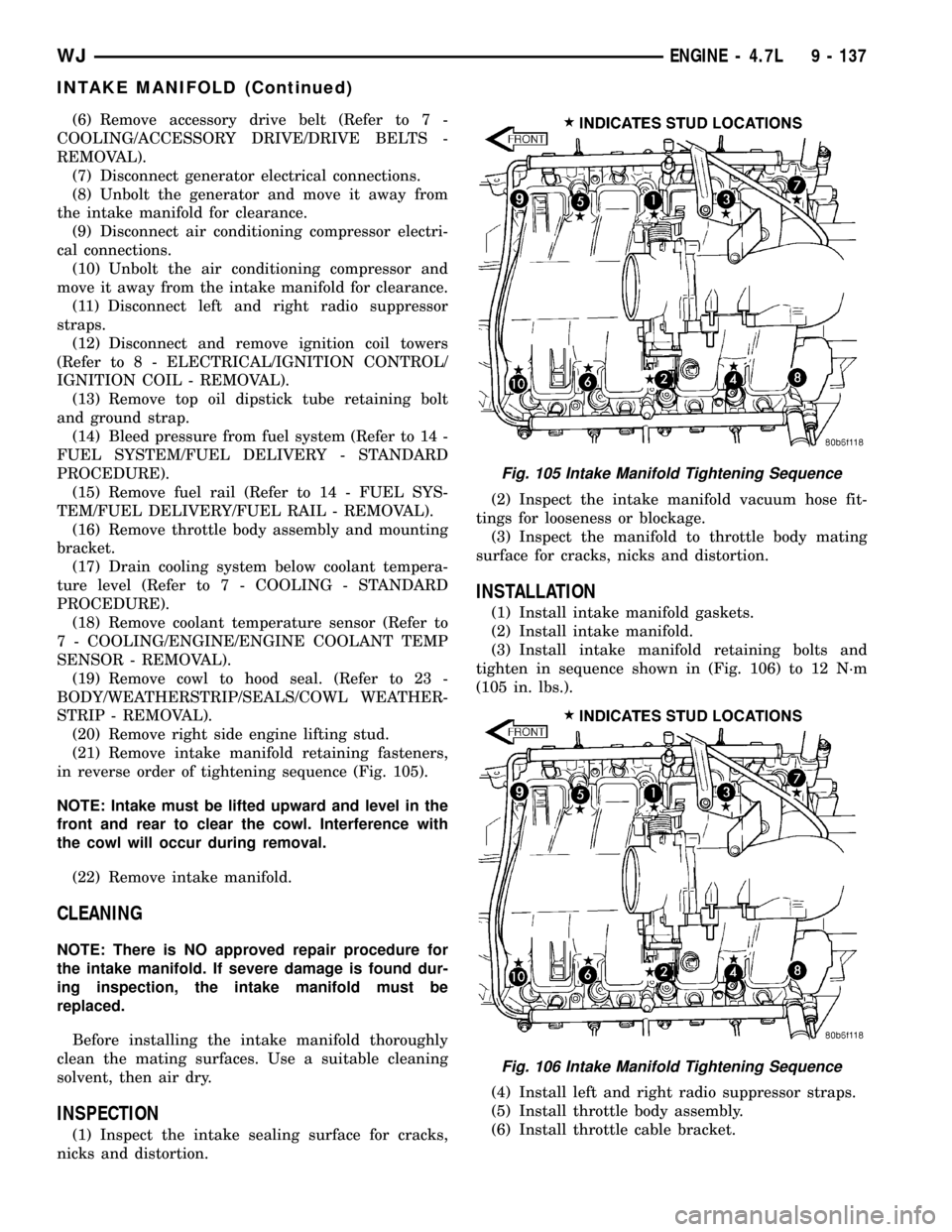
in reverse order of tightening sequence (Fig. 105).
NOTE: Intake must be lifted upward and level in the
front and rear to clear the cowl. Interference with
the cowl will occur during removal.
(22) Remove intake manifold.
CLEANING
NOTE: There is NO approved repair procedure for
the intake manifold. If severe damage is found dur-
ing inspection, the intake manifold must be
replaced.
Before installing the intake manifold thoroughly
clean the mating surfaces. Use a suitable cleaning
solvent, then air dry.
INSPECTION
(1) Inspect the intake sealing surface for cracks,
nicks and distortion.(2) Inspect the intake manifold vacuum hose fit-
tings for looseness or blockage.
(3) Inspect the manifold to throttle body mating
surface for cracks, nicks and distortion.
INSTALLATION
(1) Install intake manifold gaskets.
(2) Install intake manifold.
(3) Install intake manifold retaining bolts and
tighten in sequence shown in (Fig. 106) to 12 N´m
(105 in. lbs.).
(4) Install left and right radio suppressor straps.
(5) Install throttle body assembly.
(6) Install throttle cable bracket.
Fig. 105 Intake Manifold Tightening Sequence
Fig. 106 Intake Manifold Tightening Sequence
WJENGINE - 4.7L 9 - 137
INTAKE MANIFOLD (Continued)