2002 JEEP GRAND CHEROKEE brake fluid
[x] Cancel search: brake fluidPage 431 of 2199

For further diagnosis of the brake indicator or the
instrument cluster circuitry that controls the indica-
tor, (Refer to 8 - ELECTRICAL/INSTRUMENT
CLUSTER - DIAGNOSIS AND TESTING). The park
brake switch input to the instrument cluster can be
diagnosed using conventional diagnostic tools and
methods. For proper diagnosis of the brake fluid level
switch input to the CAB, the anti-lock brake system,
the CAB, the PCI data bus, or the electronic message
inputs to the instrument cluster that control the
brake indicator, a DRBIIItscan tool is required.
Refer to the appropriate diagnostic information.
DIAGNOSIS AND TESTING - BRAKE INDICATOR
The diagnosis found here addresses an inoperative
park brake indicator condition. If there are problems
with several indicators in the instrument cluster,
(Refer to 8 - ELECTRICAL/INSTRUMENT CLUS-
TER - DIAGNOSIS AND TESTING). If the brake
indicator stays on with the ignition switch in the On
position and the park brake released, or comes on
while driving, (Refer to 5 - BRAKES - DIAGNOSIS
AND TESTING). If no brake system problem is
found, the following procedures will help to locate a
shorted or open circuit, or a faulty park brake switch
input. Refer to the appropriate wiring information.
The wiring information includes wiring diagrams,
proper wire and connector repair procedures, details
of wire harness routing and retention, connector pin-
out information and location views for the various
wire harness connectors, splices and grounds.
WARNING: ON VEHICLES EQUIPPED WITH AIR-
BAGS, DISABLE THE SUPPLEMENTAL RESTRAINT
SYSTEM BEFORE ATTEMPTING ANY STEERING
WHEEL, STEERING COLUMN, DRIVER AIRBAG,
PASSENGER AIRBAG, SIDE CURTAIN AIRBAG,
FRONT IMPACT SENSOR, SIDE IMPACT SENSOR,
OR INSTRUMENT PANEL COMPONENT DIAGNOSIS
OR SERVICE. DISCONNECT AND ISOLATE THE
BATTERY NEGATIVE (GROUND) CABLE, THEN
WAIT TWO MINUTES FOR THE SYSTEM CAPACI-
TOR TO DISCHARGE BEFORE PERFORMING FUR-
THER DIAGNOSIS OR SERVICE. THIS IS THE ONLY
SURE WAY TO DISABLE THE SUPPLEMENTAL
RESTRAINT SYSTEM. FAILURE TO TAKE THE
PROPER PRECAUTIONS COULD RESULT IN ACCI-
DENTAL AIRBAG DEPLOYMENT AND POSSIBLE
PERSONAL INJURY.
INDICATOR ILLUMINATES DURING BULB TEST, BUT DOES
NOT WHEN PARK BRAKE APPLIED
(1) Disconnect and isolate the battery negative
cable. Disconnect the instrument panel wire harness
connector for the park brake switch from the switch
terminal. Apply the parking brake. Check for conti-nuity between the park brake switch terminal and a
good ground. There should be continuity. If OK, go to
Step 2. If not OK, replace the faulty park brake
switch.
(2) Disconnect the instrument panel wire harness
connector for the instrument cluster from the cluster
connector receptacle. Check for continuity between
the red brake warning indicator driver circuit cavi-
ties of the instrument panel wire harness connector
for the park brake switch and the instrument panel
wire harness connector for the instrument cluster.
There should be continuity. If not OK, repair the
open red brake warning indicator driver circuit
between the park brake switch and the instrument
cluster as required.
INDICATOR REMAINS ILLUMINATED - BRAKE SYSTEM
CHECKS OK
(1) Disconnect and isolate the battery negative
cable. Disconnect the instrument panel wire harness
connector for the park brake switch from the park
brake switch terminal. Check for continuity between
the terminal of the park brake switch and a good
ground. There should be no continuity with the park
brake released, and continuity with the park brake
applied. If OK, go to Step 2. If not OK, replace the
faulty park brake switch.
(2) Disconnect the instrument panel wire harness
connector for the instrument cluster from the cluster
connector receptacle. Check for continuity between
the red brake warning indicator driver circuit cavity
of the instrument panel wire harness connector for
the park brake switch and a good ground. There
should be no continuity. If not OK, repair the shorted
red brake warning indicator driver circuit between
the park brake switch and the instrument cluster as
required.
CHECK GAUGES INDICATOR
DESCRIPTION
A check gauges indicator is standard equipment on
all instrument clusters. The check gauges indicator is
located on the right edge of the instrument cluster, to
the right of the speedometer. The check gauges indi-
cator consists of the words ªCHECK GAGESº
imprinted on a red lens. The lens is located behind a
cutout in the opaque layer of the instrument cluster
overlay. The dark outer layer of the overlay prevents
the indicator from being clearly visible when it is not
illuminated. The ªCHECK GAGESº text appears sil-
houetted against a red field through the translucent
outer layer of the overlay when the indicator is illu-
minated from behind by a Light Emitting Diode
(LED), which is soldered onto the instrument cluster
electronic circuit board. The check gauges indicator
8J - 16 INSTRUMENT CLUSTERWJ
BRAKE/PARK BRAKE INDICATOR (Continued)
Page 673 of 2199

Component Page
Power Outlet......................... 8W-41
Power Seats.......................... 8W-63
Power Windows....................... 8W-60
Powertrain Control Module.............. 8W-30
Radio............................... 8W-47
Rain Sensor.......................... 8W-49
Recirculation Door Motor/Actuator........ 8W-42
Red Brake Warning Indicator Switch....... 8W-35
Remote Keyless Module................. 8W-39
Remote Radio Switches................. 8W-47
Splices.............................. 8W-10
Seat Belt Switch...................... 8W-43
Seat Module.......................... 8W-63
Sentry Key Immobilizer Module.......... 8W-39
Shifter Assembly...................... 8W-31
Side Impact Sensors................... 8W-43
Side Marker Lamps.................... 8W-50
Side Repeater Lamps................... 8W-52
Siren............................... 8W-49
Speakers............................ 8W-47Component Page
Speed Control Switches................. 8W-33
Sunroof............................. 8W-64
Temperature Valve Actuator............. 8W-42
Throttle Position Sensor................ 8W-30
Trailer Tow.......................... 8W-54
Transfer Case Position Sensor............ 8W-31
Transmission......................... 8W-31
Turn Signal Lamps.................... 8W-52
Underhood Lamp...................... 8W-44
Vehicle Information Center.............. 8W-49
Viscous/Cabin Heater................... 8W-30
Visor/Vanity Lamps.................... 8W-44
Washer Fluid Level Switch.............. 8W-53
Wastegate Solenoid.................... 8W-30
Water In Fuel Sensor................... 8W-30
Wheel Speed Sensors................... 8W-35
Window Defogger...................... 8W-48
Wiper High/Low Relay.................. 8W-53
Wiper Motor.......................... 8W-53
Washer Pump......................... 8W-5
8W - 02 - 2 8W-02 COMPONENT INDEXWJ
Page 742 of 2199

8W-15 GROUND DISTRIBUTION
Component Page
A/C Compressor Clutch.................. 8W-15-4
Adjustable Pedals Module............. 8W-15-17, 21
Airbag Control Module.................. 8W-15-16
Ash Receiver Lamp.................... 8W-15-14
Automatic Day/Night Mirror.............. 8W-15-19
Automatic Zone Control Module........... 8W-15-15
Battery............................ 8W-15-2, 3
Blower Motor Controller................. 8W-15-15
Body Control Module.............. 8W-15-12, 13, 15
Brake Lamp Switch................. 8W-15-17, 22
Center High Mounted Stop Lamp.......... 8W-15-20
Cigar Lighter........................ 8W-15-14
Cigar Lighter Relay.................... 8W-15-12
Controller Antilock Brake................ 8W-15-12
Coolant Level Sensor............... 8W-15-9, 10, 11
Crankcase Heater...................... 8W-15-4
Data Link Connector.................. 8W-15-2, 3
Driver Cylinder Lock Switch.............. 8W-15-16
Driver Door Lock Motor/Ajar Switch........ 8W-15-16
Driver Door Module.................... 8W-15-16
Driver Heated Seat Switch............... 8W-15-14
Driver Lumbar Switch............... 8W-15-18, 21
Driver Power Seat Switch............. 8W-15-18, 21
Driver Rear Power Window Switch....... 8W-15-18, 21
Electric Brake........................ 8W-15-17
Electronic Speed Control Servo.......... 8W-15-9, 10
Engine Control Module.................. 8W-15-3
Front Power Outlet.................... 8W-15-14
Front Washer Pump................... 8W-15-6, 7
Front Wiper Motor.................... 8W-15-6, 7
Fuel Pump Module.................... 8W-15-19
G100............................. 8W-15-2, 3
G101............................. 8W-15-2, 3
G102............................... 8W-15-2
G103............................. 8W-15-2, 3
G104............................... 8W-15-4
G105............................... 8W-15-4
G106............................. 8W-15-6, 7
G107.............................. 8W-15-12
G108.......................... 8W-15-9, 10, 11
G200......................... 8W-15-13, 14, 15
G201.............................. 8W-15-16
G300......................... 8W-15-16, 17, 18
G301......................... 8W-15-19, 21, 22
Headlamp Leveling Switch............... 8W-15-15
Hood Ajar Switch..................... 8W-15-6, 7
Horn No. 1...................... 8W-15-9, 10, 11
Horn No. 2...................... 8W-15-9, 10, 11
Hydraulic Cooling Module........... 8W-15-9, 10, 11
Ignition Switch....................... 8W-15-15
Instrument Cluster.................. 8W-15-13, 14
Intake Port Swirl Actuator................ 8W-15-3
Intrusion Transceiver Module.......... 8W-15-21, 22
Junction Block.................. 8W-15-12, 13, 15
Left Fog Lamp...................... 8W-15-6, 7
Left Front Park Lamp................... 8W-15-5
Left Front Park/Turn Signal Lamp.......... 8W-15-5
Left Front Turn Signal Lamp.............. 8W-15-5
Left Headlamp Leveling Motor............. 8W-15-5
Left High Beam Headlamp................ 8W-15-5
Component Page
Left Liftgate Ajar Switch................ 8W-15-20
Left Low Beam Headlamp................ 8W-15-5
Left Multi-Function Switch............... 8W-15-15
Left Rear Door Lock Motor/Ajar Switch.... 8W-15-21, 22
Left Rear Lamp Assembly............... 8W-15-19
Left Side Repeater Lamp............... 8W-15-6, 7
License Lamp No. 1.................... 8W-15-20
License Lamp No. 2.................... 8W-15-20
Liftgate Flip-Up Ajar Switch.............. 8W-15-20
Liftgate Flip-Up Release Solenoid.......... 8W-15-20
Line Pressure Sensor.................... 8W-15-2
Low Beam/Daytime Running Lamp Relay.... 8W-15-12
Manual Temperature Control........... 8W-15-13, 15
Oxygen Sensor 1/2 Downstream............ 8W-15-4
Oxygen Sensor 2/2 Downstream............ 8W-15-4
Park Lamp Relay..................... 8W-15-12
Passenger Door Lock Motor/Ajar Switch...... 8W-15-16
Passenger Door Module................. 8W-15-16
Passenger Heated Seat Switch............ 8W-15-14
Passenger Lumbar Switch............. 8W-15-17, 22
Passenger Power Seat Switch.......... 8W-15-17, 22
Passenger Rear Power Window Switch.... 8W-15-16, 22
Power Amplifier.................... 8W-15-17, 18
Power Connector...................... 8W-15-15
Powertrain Control Module............... 8W-15-2
Radio........................... 8W-15-17, 18
Rain Sensor....................... 8W-15-21, 22
Rear Power Outlet.................. 8W-15-17, 18
Rear Washer Pump................... 8W-15-6, 7
Rear Window Defogger.................. 8W-15-20
Rear Wiper Motor..................... 8W-15-20
Remote Keyless Module................. 8W-15-16
Right Fog Lamp.................. 8W-15-9, 10, 11
Right Front Park Lamp.................. 8W-15-8
Right Front Park/Turn Signal Lamp......... 8W-15-8
Right Front Turn Signal Lamp............. 8W-15-8
Right Headlamp Leveling Motor............ 8W-15-8
Right High Beam Headlamp............... 8W-15-8
Right Low Beam Headlamp............... 8W-15-8
Right Rear Door Lock Motor/Ajar Switch . . 8W-15-16, 18
Right Rear Lamp Assembly............ 8W-15-17, 18
Right Side Repeater Lamp........... 8W-15-9, 10, 11
Seat Module...................... 8W-15-18, 21
Sentry Key Immobilizer Module........... 8W-15-13
Shifter Assembly................... 8W-15-14, 15
Siren............................. 8W-15-6, 7
Sunroof Control Module................. 8W-15-19
Sunroof Motor........................ 8W-15-19
Sunroof Switch....................... 8W-15-19
Temperature Valve Actuator.............. 8W-15-13
Trailer Tow Brake Lamp Relay............ 8W-15-19
Trailer Tow Connector.................. 8W-15-19
Trailer Tow Left Turn Relay.............. 8W-15-19
Trailer Tow Right Turn Relay............. 8W-15-19
Transmission Control Module.............. 8W-15-2
Transmission Control Relay............ 8W-15-9, 10
Underhood Lamp..................... 8W-15-6, 7
Vehicle Information Center............ 8W-15-21, 22
Viscous/Cabin Heater................... 8W-15-4
Washer Fluid Level Switch.............. 8W-15-6, 7
WJ8W-15 GROUND DISTRIBUTION 8W - 15 - 1
Page 1052 of 2199

Component Page
RIGHT FRONT WHEEL SPEED
SENSOR....................... 8W-80-115
RIGHT HEADLAMP LEVELING MOTOR
(BUILT-UP-EXPORT)............. 8W-80-115
RIGHT HIGH BEAM HEADLAMP..... 8W-80-116
RIGHT INSTRUMENT PANEL
SPEAKER...................... 8W-80-116
RIGHT LIFTGATE AJAR SWITCH..... 8W-80-116
RIGHT LOW BEAM HEADLAMP..... 8W-80-116
RIGHT MULTI-FUNCTION SWITCH . . . 8W-80-116
RIGHT REAR DOOR LOCK
MOTOR/AJAR SWITCH........... 8W-80-117
RIGHT REAR DOOR SPEAKER....... 8W-80-117
RIGHT REAR LAMP ASSEMBLY...... 8W-80-117
RIGHT REAR WHEEL SPEED
SENSOR....................... 8W-80-117
RIGHT REMOTE RADIO SWITCH.... 8W-80-117
RIGHT SIDE REPEATER LAMP
(BUILT-UP-EXPORT)............. 8W-80-118
RIGHT VISOR/VANITY LAMP........ 8W-80-118
SEAT BELT SWITCH............... 8W-80-118
SEAT MODULE C1 (PREMIUM)...... 8W-80-118
SEAT MODULE C2 (PREMIUM)...... 8W-80-119
SENTRY KEY IMMOBILIZER
MODULE...................... 8W-80-119
SHIFTER ASSEMBLY
(C201 DIESEL).................. 8W-80-119
SHIFTER ASSEMBLY (GAS)......... 8W-80-120
SHIFTER ASSEMBLY C1 (DIESEL).... 8W-80-120
SHIFTER ASSEMBLY C2 (DIESEL).... 8W-80-120
SIREN (BUILT-UP-EXPORT)......... 8W-80-120
SPEED CONTROL SWITCH NO. 1.... 8W-80-120
SPEED CONTROL SWITCH NO. 2.... 8W-80-121
SUNROOF CONTROL MODULE...... 8W-80-121
SUNROOF MOTOR C1.............. 8W-80-121
SUNROOF MOTOR C2.............. 8W-80-121
SUNROOF SWITCH................ 8W-80-121Component Page
TEMPERATURE VALVE
ACTUATOR (MTC)............... 8W-80-122
THROTTLE POSITION
SENSOR (4.0L).................. 8W-80-122
THROTTLE POSITION
SENSOR (4.7L).................. 8W-80-122
TRAILER TOW BRAKE
LAMP RELAY................... 8W-80-122
TRAILER TOW CIRCUIT
BREAKER...................... 8W-80-122
TRAILER TOW CONNECTOR........ 8W-80-123
TRAILER TOW LEFT TURN
RELAY........................ 8W-80-123
TRAILER TOW RIGHT TURN
RELAY........................ 8W-80-123
TRANSFER CASE POSITION
SENSOR....................... 8W-80-123
TRANSMISSION CONTROL
MODULE (4.7L)................. 8W-80-124
TRANSMISSION CONTROL
MODULE C1 (DIESEL)........... 8W-80-125
TRANSMISSION CONTROL
MODULE C2 (DIESEL)........... 8W-80-125
TRANSMISSION SOLENOID (4.0L).... 8W-80-125
TRANSMISSION SOLENOID
ASSEMBLY (DIESEL)............ 8W-80-126
TRANSMISSION SOLENOID/TRS
ASSEMBLY (4.7L)................ 8W-80-126
UNDERHOOD LAMP............... 8W-80-126
VEHICLE INFORMATION CENTER . . . 8W-80-127
VISCOUS/CABIN HEATER
(DIESEL)...................... 8W-80-127
WASHER FLUID LEVEL SWITCH.... 8W-80-127
WASTEGATE SOLENOID
(DIESEL)...................... 8W-80-127
WATER IN FUEL SENSOR
(DIESEL)...................... 8W-80-127
WJ8W-80 CONNECTOR PIN-OUT 8W - 80 - 5
Page 1111 of 2199

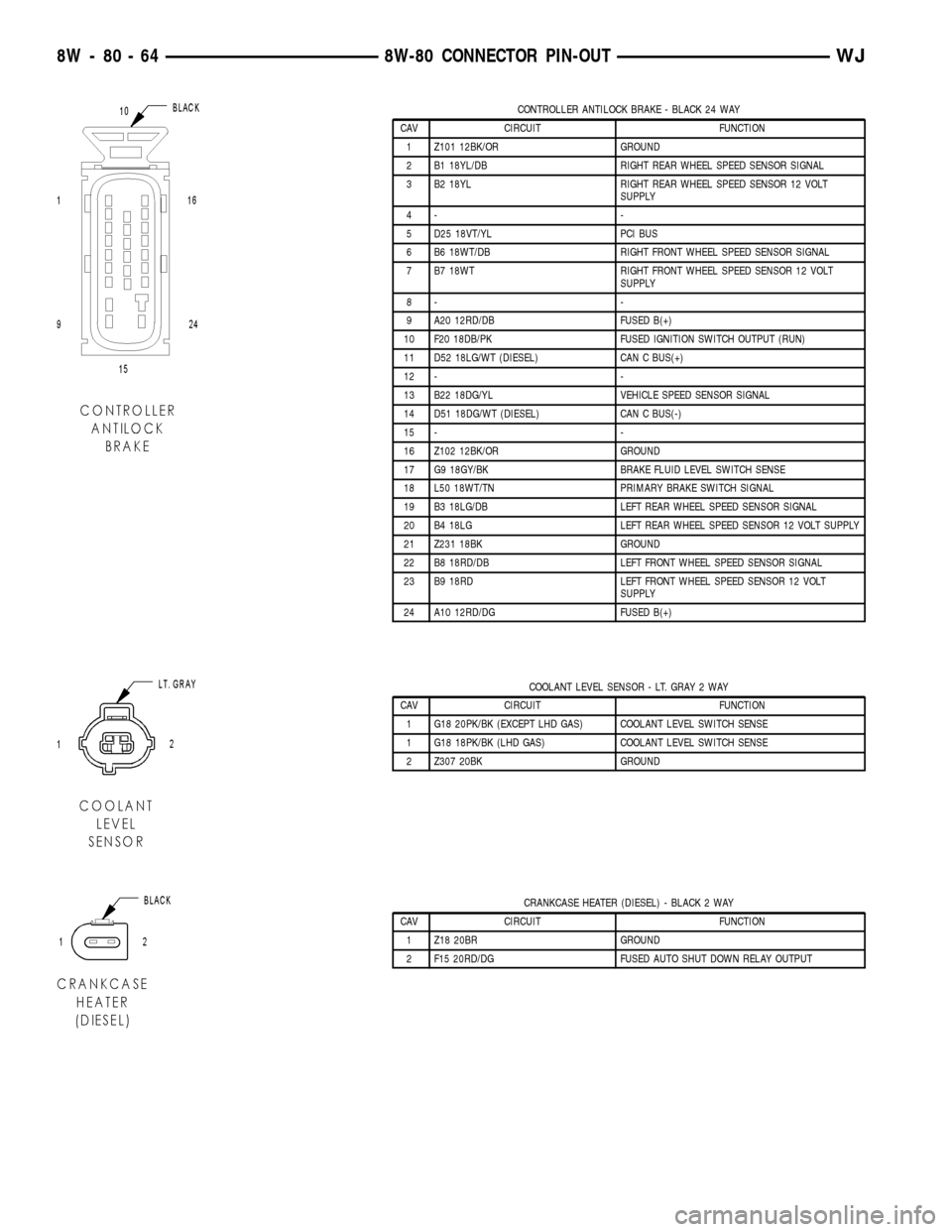
CONTROLLER ANTILOCK BRAKE - BLACK 24 WAY
CAV CIRCUIT FUNCTION
1 Z101 12BK/OR GROUND
2 B1 18YL/DB RIGHT REAR WHEEL SPEED SENSOR SIGNAL
3 B2 18YL RIGHT REAR WHEEL SPEED SENSOR 12 VOLT
SUPPLY
4- -
5 D25 18VT/YL PCI BUS
6 B6 18WT/DB RIGHT FRONT WHEEL SPEED SENSOR SIGNAL
7 B7 18WT RIGHT FRONT WHEEL SPEED SENSOR 12 VOLT
SUPPLY
8- -
9 A20 12RD/DB FUSED B(+)
10 F20 18DB/PK FUSED IGNITION SWITCH OUTPUT (RUN)
11 D52 18LG/WT (DIESEL) CAN C BUS(+)
12 - -
13 B22 18DG/YL VEHICLE SPEED SENSOR SIGNAL
14 D51 18DG/WT (DIESEL) CAN C BUS(-)
15 - -
16 Z102 12BK/OR GROUND
17 G9 18GY/BK BRAKE FLUID LEVEL SWITCH SENSE
18 L50 18WT/TN PRIMARY BRAKE SWITCH SIGNAL
19 B3 18LG/DB LEFT REAR WHEEL SPEED SENSOR SIGNAL
20 B4 18LG LEFT REAR WHEEL SPEED SENSOR 12 VOLT SUPPLY
21 Z231 18BK GROUND
22 B8 18RD/DB LEFT FRONT WHEEL SPEED SENSOR SIGNAL
23 B9 18RD LEFT FRONT WHEEL SPEED SENSOR 12 VOLT
SUPPLY
24 A10 12RD/DG FUSED B(+)
COOLANT LEVEL SENSOR - LT. GRAY 2 WAY
CAV CIRCUIT FUNCTION
1 G18 20PK/BK (EXCEPT LHD GAS) COOLANT LEVEL SWITCH SENSE
1 G18 18PK/BK (LHD GAS) COOLANT LEVEL SWITCH SENSE
2 Z307 20BK GROUND
CRANKCASE HEATER (DIESEL) - BLACK 2 WAY
CAV CIRCUIT FUNCTION
1 Z18 20BR GROUND
2 F15 20RD/DG FUSED AUTO SHUT DOWN RELAY OUTPUT
8W - 80 - 64 8W-80 CONNECTOR PIN-OUTWJ
Page 1186 of 2199

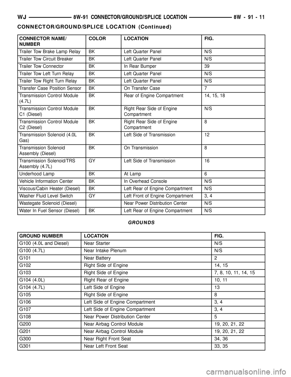
CONNECTOR NAME/
NUMBERCOLOR LOCATION FIG.
Trailer Tow Brake Lamp Relay BK Left Quarter Panel N/S
Trailer Tow Circuit Breaker BK Left Quarter Panel N/S
Trailer Tow Connector BK In Rear Bumper 39
Trailer Tow Left Turn Relay BK Left Quarter Panel N/S
Trailer Tow Right Turn Relay BK Left Quarter Panel N/S
Transfer Case Position Sensor BK On Transfer Case 7
Transmission Control Module
(4.7L)BK Rear of Engine Compartment 14, 15, 18
Transmission Control Module
C1 (Diesel)BK Right Rear Side of Engine
CompartmentN/S
Transmission Control Module
C2 (Diesel)BK Right Rear Side of Engine
Compartment8
Transmission Solenoid (4.0L
Gas)BK Left Side of Transmission 12
Transmission Solenoid
Assembly (Diesel)BK On Transmission 8
Transmission Solenoid/TRS
Assembly (4.7L)GY Left Side of Transmission 16
Underhood Lamp BK At Lamp 6
Vehicle Information Center BK In Overhead Console N/S
Viscous/Cabin Heater (Diesel) BK Left Rear of Engine Compartment N/S
Washer Fluid Level Switch GY Left Front of Engine Compartment 3, 4
Wastegate Solenoid (Diesel) Near Power Distribution Center N/S
Water In Fuel Sensor (Diesel) BK Left Rear of Engine Compartment N/S
GROUNDS
GROUND NUMBER LOCATION FIG.
G100 (4.0L and Diesel) Near Starter N/S
G100 (4.7L) Near Intake Plenum N/S
G101 Near Battery 2
G102 Right Side of Engine 14, 15
G103 Right Side of Engine 7, 8, 10, 11, 14, 15
G104 (4.0L) Right Rear of Engine 10, 11
G104 (4.7L) Left Side of Engine 13
G105 Right Side of Engine 8
G106 Left Side of Engine Compartment 3, 4
G107 Left Side of Engine Compartment 3, 4
G108 Near Power Distribution Center 5
G200 Near Airbag Control Module 19, 20, 21, 22
G201 Near Airbag Control Module 19, 20, 21, 22
G300 Near Right Front Seat 34, 36
G301 Near Left Front Seat 33, 35
WJ8W-91 CONNECTOR/GROUND/SPLICE LOCATION 8W - 91 - 11
CONNECTOR/GROUND/SPLICE LOCATION (Continued)
Page 1189 of 2199

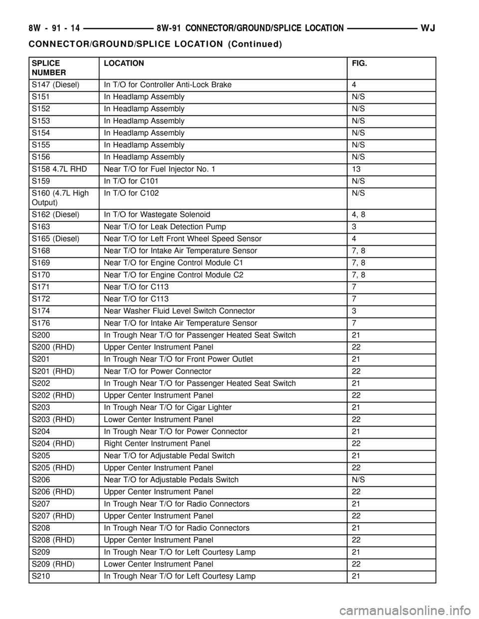
SPLICE
NUMBERLOCATION FIG.
S147 (Diesel) In T/O for Controller Anti-Lock Brake 4
S151 In Headlamp Assembly N/S
S152 In Headlamp Assembly N/S
S153 In Headlamp Assembly N/S
S154 In Headlamp Assembly N/S
S155 In Headlamp Assembly N/S
S156 In Headlamp Assembly N/S
S158 4.7L RHD Near T/O for Fuel Injector No. 1 13
S159 In T/O for C101 N/S
S160 (4.7L High
Output)In T/O for C102 N/S
S162 (Diesel) In T/O for Wastegate Solenoid 4, 8
S163 Near T/O for Leak Detection Pump 3
S165 (Diesel) Near T/O for Left Front Wheel Speed Sensor 4
S168 Near T/O for Intake Air Temperature Sensor 7, 8
S169 Near T/O for Engine Control Module C1 7, 8
S170 Near T/O for Engine Control Module C2 7, 8
S171 Near T/O for C113 7
S172 Near T/O for C113 7
S174 Near Washer Fluid Level Switch Connector 3
S176 Near T/O for Intake Air Temperature Sensor 7
S200 In Trough Near T/O for Passenger Heated Seat Switch 21
S200 (RHD) Upper Center Instrument Panel 22
S201 In Trough Near T/O for Front Power Outlet 21
S201 (RHD) Near T/O for Power Connector 22
S202 In Trough Near T/O for Passenger Heated Seat Switch 21
S202 (RHD) Upper Center Instrument Panel 22
S203 In Trough Near T/O for Cigar Lighter 21
S203 (RHD) Lower Center Instrument Panel 22
S204 In Trough Near T/O for Power Connector 21
S204 (RHD) Right Center Instrument Panel 22
S205 Near T/O for Adjustable Pedal Switch 21
S205 (RHD) Upper Center Instrument Panel 22
S206 Near T/O for Adjustable Pedals Switch N/S
S206 (RHD) Upper Center Instrument Panel 22
S207 In Trough Near T/O for Radio Connectors 21
S207 (RHD) Upper Center Instrument Panel 22
S208 In Trough Near T/O for Radio Connectors 21
S208 (RHD) Upper Center Instrument Panel 22
S209 In Trough Near T/O for Left Courtesy Lamp 21
S209 (RHD) Lower Center Instrument Panel 22
S210 In Trough Near T/O for Left Courtesy Lamp 21
8W - 91 - 14 8W-91 CONNECTOR/GROUND/SPLICE LOCATIONWJ
CONNECTOR/GROUND/SPLICE LOCATION (Continued)
Page 1520 of 2199

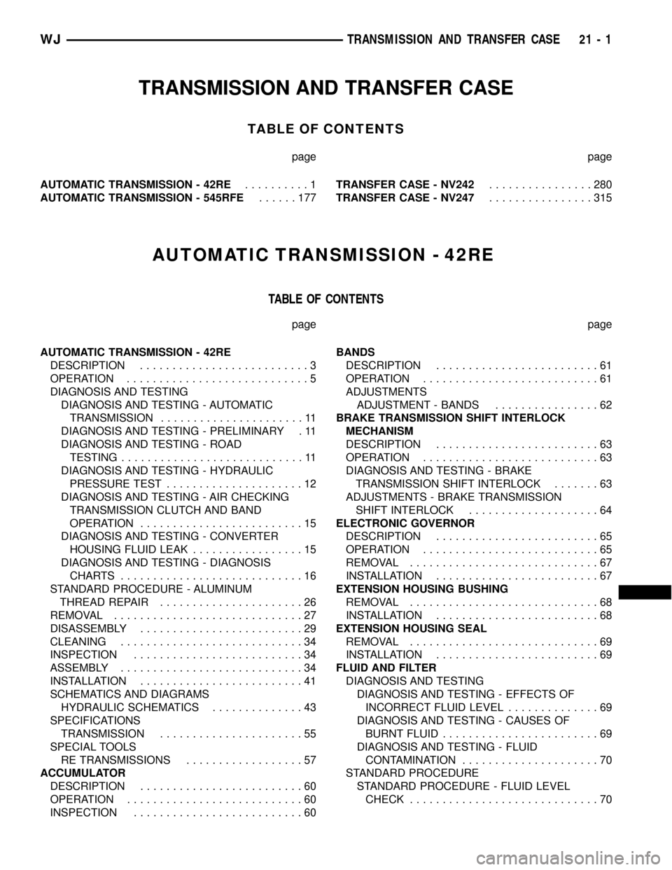
TRANSMISSION AND TRANSFER CASE
TABLE OF CONTENTS
page page
AUTOMATIC TRANSMISSION - 42RE..........1
AUTOMATIC TRANSMISSION - 545RFE......177TRANSFER CASE - NV242................280
TRANSFER CASE - NV247................315
AUTOMATIC TRANSMISSION - 42RE
TABLE OF CONTENTS
page page
AUTOMATIC TRANSMISSION - 42RE
DESCRIPTION..........................3
OPERATION............................5
DIAGNOSIS AND TESTING
DIAGNOSIS AND TESTING - AUTOMATIC
TRANSMISSION......................11
DIAGNOSIS AND TESTING - PRELIMINARY . 11
DIAGNOSIS AND TESTING - ROAD
TESTING............................11
DIAGNOSIS AND TESTING - HYDRAULIC
PRESSURE TEST.....................12
DIAGNOSIS AND TESTING - AIR CHECKING
TRANSMISSION CLUTCH AND BAND
OPERATION.........................15
DIAGNOSIS AND TESTING - CONVERTER
HOUSING FLUID LEAK.................15
DIAGNOSIS AND TESTING - DIAGNOSIS
CHARTS............................16
STANDARD PROCEDURE - ALUMINUM
THREAD REPAIR......................26
REMOVAL.............................27
DISASSEMBLY.........................29
CLEANING............................34
INSPECTION..........................34
ASSEMBLY............................34
INSTALLATION.........................41
SCHEMATICS AND DIAGRAMS
HYDRAULIC SCHEMATICS..............43
SPECIFICATIONS
TRANSMISSION......................55
SPECIAL TOOLS
RE TRANSMISSIONS..................57
ACCUMULATOR
DESCRIPTION.........................60
OPERATION...........................60
INSPECTION..........................60BANDS
DESCRIPTION.........................61
OPERATION...........................61
ADJUSTMENTS
ADJUSTMENT - BANDS................62
BRAKE TRANSMISSION SHIFT INTERLOCK
MECHANISM
DESCRIPTION.........................63
OPERATION...........................63
DIAGNOSIS AND TESTING - BRAKE
TRANSMISSION SHIFT INTERLOCK.......63
ADJUSTMENTS - BRAKE TRANSMISSION
SHIFT INTERLOCK....................64
ELECTRONIC GOVERNOR
DESCRIPTION.........................65
OPERATION...........................65
REMOVAL.............................67
INSTALLATION.........................67
EXTENSION HOUSING BUSHING
REMOVAL.............................68
INSTALLATION.........................68
EXTENSION HOUSING SEAL
REMOVAL.............................69
INSTALLATION.........................69
FLUID AND FILTER
DIAGNOSIS AND TESTING
DIAGNOSIS AND TESTING - EFFECTS OF
INCORRECT FLUID LEVEL..............69
DIAGNOSIS AND TESTING - CAUSES OF
BURNT FLUID........................69
DIAGNOSIS AND TESTING - FLUID
CONTAMINATION.....................70
STANDARD PROCEDURE
STANDARD PROCEDURE - FLUID LEVEL
CHECK.............................70
WJTRANSMISSION AND TRANSFER CASE 21 - 1