2002 JEEP GRAND CHEROKEE Seat cushion
[x] Cancel search: Seat cushionPage 1051 of 2199

Component Page
LIFTGATE FLIP-UP PUSH
BUTTON SWITCH................ 8W-80-97
LIFTGATE FLIP-UP RELEASE
SOLENOID...................... 8W-80-97
LIFTGATE POWER LOCK MOTOR..... 8W-80-97
LINE PRESSURE SENSOR (4.7L)...... 8W-80-98
MANIFOLD ABSOLUTE PRESSURE
SENSOR (4.0L)................... 8W-80-98
MANIFOLD ABSOLUTE PRESSURE
SENSOR (4.7L)................... 8W-80-98
MANUAL TEMPERATURE
CONTROL C1 (MTC).............. 8W-80-98
MANUAL TEMPERATURE
CONTROL C2 (MTC).............. 8W-80-99
MASS AIR FLOW SENSOR (DIESEL) . . . 8W-80-99
MODE DOOR MOTOR/ACTUATOR
(AZC).......................... 8W-80-99
NEEDLE MOVEMENT SENSOR
(DIESEL)....................... 8W-80-99
OUTPUT SPEED SENSOR (4.0L)...... 8W-80-99
OUTPUT SPEED SENSOR (4.7L)..... 8W-80-100
OVERHEAD MAP/COURTESY LAMP . . 8W-80-100
OXYGEN SENSOR 1/1 UPSTREAM.... 8W-80-100
OXYGEN SENSOR 1/2 DOWNSTREAM . 8W-80-100
OXYGEN SENSOR 2/1 UPSTREAM.... 8W-80-100
OXYGEN SENSOR 2/2
DOWNSTREAM................. 8W-80-101
PARK/NEUTRAL POSITION SWITCH
(4.0L).......................... 8W-80-101
PARK/NEUTRAL POSITION SWITCH
(DIESEL)...................... 8W-80-101
PASSENGER AIRBAG.............. 8W-80-101
PASSENGER BLEND DOOR
MOTOR/ACTUATOR (LHD) (AZC) . . . 8W-80-101
PASSENGER BLEND DOOR
MOTOR/ACTUATOR (RHD) (AZC) . . . 8W-80-102
PASSENGER CURTAIN AIRBAG...... 8W-80-102
PASSENGER DOOR LOCK MOTOR/AJAR
SWITCH....................... 8W-80-102
PASSENGER DOOR MODULE C1..... 8W-80-102
PASSENGER DOOR MODULE C2..... 8W-80-103
PASSENGER FRONT DOOR
COURTESY LAMP............... 8W-80-103
PASSENGER FRONT POWER
WINDOW MOTOR............... 8W-80-103
PASSENGER HEATED SEAT BACK
(PREMIUM I/III)................. 8W-80-103
PASSENGER HEATED SEAT CUSHION
(PREMIUM I/III)................. 8W-80-104
PASSENGER HEATED SEAT SWITCH . 8W-80-104
PASSENGER LUMBAR MOTOR
(MIDLINE/PREMIUM)............ 8W-80-104
PASSENGER LUMBAR SWITCH
(MIDLINE/PREMIUM)............ 8W-80-104
PASSENGER POWER MIRROR....... 8W-80-105Component Page
PASSENGER POWER SEAT FRONT
RISER MOTOR.................. 8W-80-105
PASSENGER POWER SEAT
HORIZONTAL MOTOR........... 8W-80-105
PASSENGER POWER SEAT REAR
RISER MOTOR.................. 8W-80-105
PASSENGER POWER SEAT RECLINER
MOTOR (MIDLINE/PREMIUM)..... 8W-80-106
PASSENGER POWER SEAT SWITCH
(MIDLINE/PREMIUM)............ 8W-80-106
PASSENGER REAR POWER
WINDOW MOTOR............... 8W-80-106
PASSENGER REAR POWER
WINDOW SWITCH............... 8W-80-106
PASSENGER SEAT BELT SWITCH.... 8W-80-106
PASSENGER SIDE IMPACT
SENSOR....................... 8W-80-107
POWER AMPLIFIER C1
(PREMIUM RADIO).............. 8W-80-107
POWER AMPLIFIER C2
(PREMIUM RADIO).............. 8W-80-107
POWER CONNECTOR.............. 8W-80-108
POWERTRAIN CONTROL
MODULE C1 (GAS).............. 8W-80-108
POWERTRAIN CONTROL
MODULE C2 (GAS).............. 8W-80-109
POWERTRAIN CONTROL
MODULE C3 (GAS).............. 8W-80-110
RADIATOR FAN MOTOR............ 8W-80-110
RADIATOR FAN RELAY............. 8W-80-111
RADIO C1........................ 8W-80-111
RADIO C2........................ 8W-80-111
RAIN SENSOR (AUTOWIPE)......... 8W-80-112
REAR POWER OUTLET............. 8W-80-112
REAR WASHER PUMP.............. 8W-80-112
REAR WIPER MOTOR.............. 8W-80-112
RECIRCULATION DOOR
MOTOR/ACTUATOR (AZC)......... 8W-80-112
RED BRAKE WARNING INDICATOR
SWITCH....................... 8W-80-113
REMOTE KEYLESS MODULE
(JAPAN)....................... 8W-80-113
RIGHT COURTESY LAMP........... 8W-80-113
RIGHT DOOR HANDLE
COURTESY LAMP............... 8W-80-113
RIGHT FOG LAMP................. 8W-80-113
RIGHT FRONT DOOR SPEAKER..... 8W-80-114
RIGHT FRONT IMPACT SENSOR..... 8W-80-114
RIGHT FRONT PARK LAMP......... 8W-80-114
RIGHT FRONT PARK/TURN SIGNAL LAMP
(EXCEPT BUILT-UP-EXPORT)...... 8W-80-114
RIGHT FRONT SIDE MARKER LAMP
(EXCEPT BUILT-UP-EXPORT)...... 8W-80-115
RIGHT FRONT TURN SIGNAL LAMP
(BUILT-UP-EXPORT)............. 8W-80-115
8W - 80 - 4 8W-80 CONNECTOR PIN-OUTWJ
Page 1116 of 2199
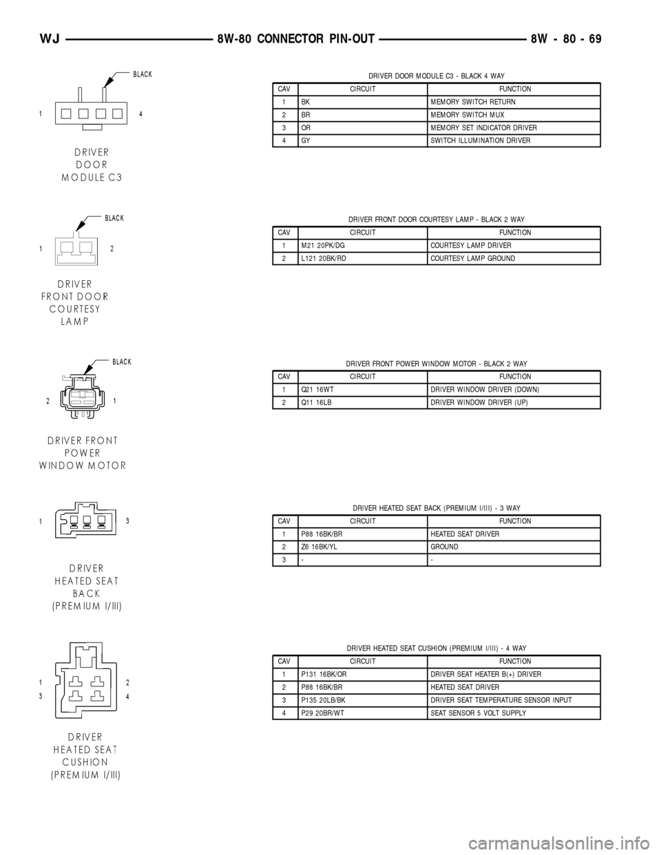
DRIVER DOOR MODULE C3 - BLACK 4 WAY
CAV CIRCUIT FUNCTION
1 BK MEMORY SWITCH RETURN
2 BR MEMORY SWITCH MUX
3 OR MEMORY SET INDICATOR DRIVER
4 GY SWITCH ILLUMINATION DRIVER
DRIVER FRONT DOOR COURTESY LAMP - BLACK 2 WAY
CAV CIRCUIT FUNCTION
1 M21 20PK/DG COURTESY LAMP DRIVER
2 L121 20BK/RD COURTESY LAMP GROUND
DRIVER FRONT POWER WINDOW MOTOR - BLACK 2 WAY
CAV CIRCUIT FUNCTION
1 Q21 16WT DRIVER WINDOW DRIVER (DOWN)
2 Q11 16LB DRIVER WINDOW DRIVER (UP)
DRIVER HEATED SEAT BACK (PREMIUM I/III)-3WAY
CAV CIRCUIT FUNCTION
1 P88 16BK/BR HEATED SEAT DRIVER
2 Z6 16BK/YL GROUND
3- -
DRIVER HEATED SEAT CUSHION (PREMIUM I/III)-4WAY
CAV CIRCUIT FUNCTION
1 P131 16BK/OR DRIVER SEAT HEATER B(+) DRIVER
2 P88 16BK/BR HEATED SEAT DRIVER
3 P135 20LB/BK DRIVER SEAT TEMPERATURE SENSOR INPUT
4 P29 20BR/WT SEAT SENSOR 5 VOLT SUPPLY
WJ8W-80 CONNECTOR PIN-OUT 8W - 80 - 69
Page 1151 of 2199
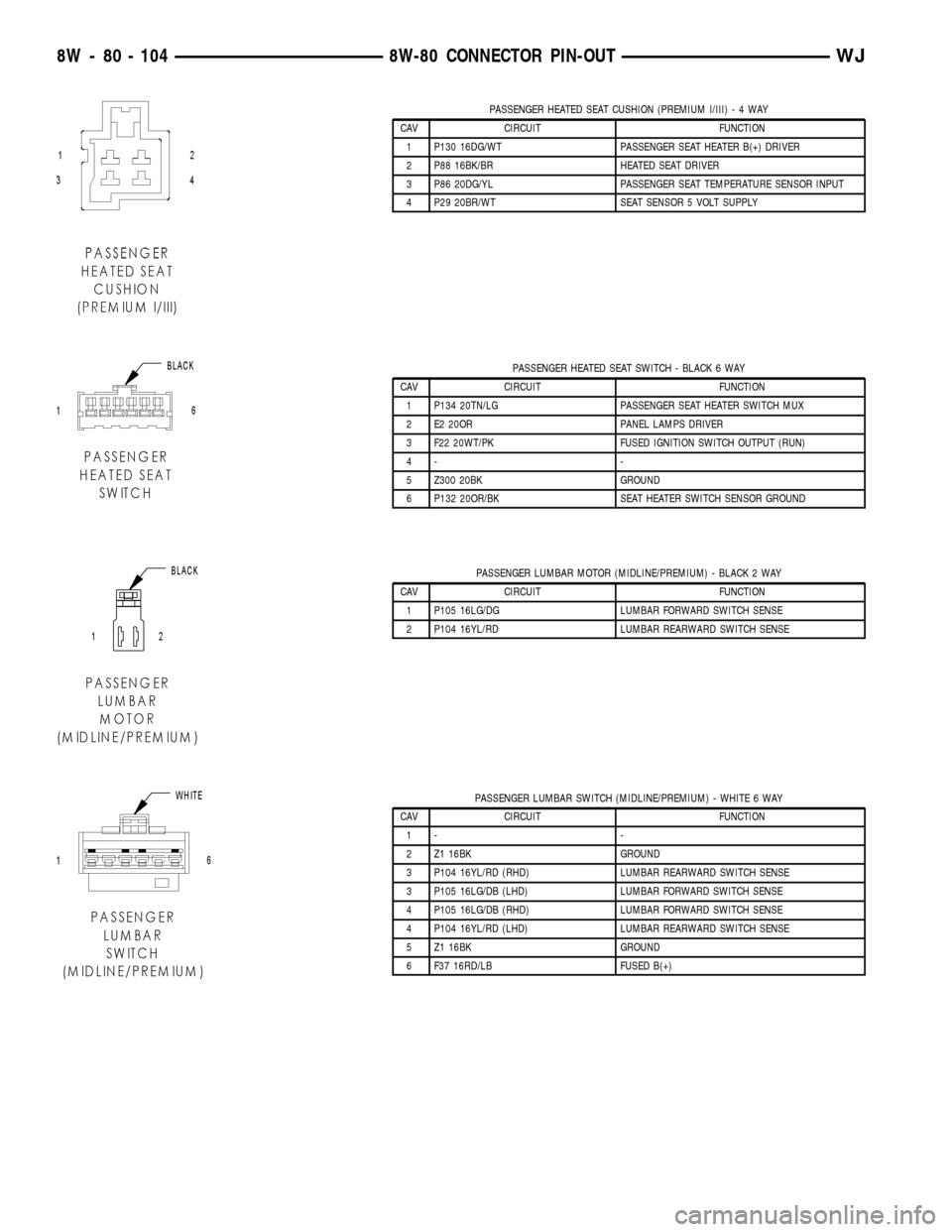
PASSENGER HEATED SEAT CUSHION (PREMIUM I/III)-4WAY
CAV CIRCUIT FUNCTION
1 P130 16DG/WT PASSENGER SEAT HEATER B(+) DRIVER
2 P88 16BK/BR HEATED SEAT DRIVER
3 P86 20DG/YL PASSENGER SEAT TEMPERATURE SENSOR INPUT
4 P29 20BR/WT SEAT SENSOR 5 VOLT SUPPLY
PASSENGER HEATED SEAT SWITCH - BLACK 6 WAY
CAV CIRCUIT FUNCTION
1 P134 20TN/LG PASSENGER SEAT HEATER SWITCH MUX
2 E2 20OR PANEL LAMPS DRIVER
3 F22 20WT/PK FUSED IGNITION SWITCH OUTPUT (RUN)
4- -
5 Z300 20BK GROUND
6 P132 20OR/BK SEAT HEATER SWITCH SENSOR GROUND
PASSENGER LUMBAR MOTOR (MIDLINE/PREMIUM) - BLACK 2 WAY
CAV CIRCUIT FUNCTION
1 P105 16LG/DG LUMBAR FORWARD SWITCH SENSE
2 P104 16YL/RD LUMBAR REARWARD SWITCH SENSE
PASSENGER LUMBAR SWITCH (MIDLINE/PREMIUM) - WHITE 6 WAY
CAV CIRCUIT FUNCTION
1- -
2 Z1 16BK GROUND
3 P104 16YL/RD (RHD) LUMBAR REARWARD SWITCH SENSE
3 P105 16LG/DB (LHD) LUMBAR FORWARD SWITCH SENSE
4 P105 16LG/DB (RHD) LUMBAR FORWARD SWITCH SENSE
4 P104 16YL/RD (LHD) LUMBAR REARWARD SWITCH SENSE
5 Z1 16BK GROUND
6 F37 16RD/LB FUSED B(+)
8W - 80 - 104 8W-80 CONNECTOR PIN-OUTWJ
Page 1179 of 2199
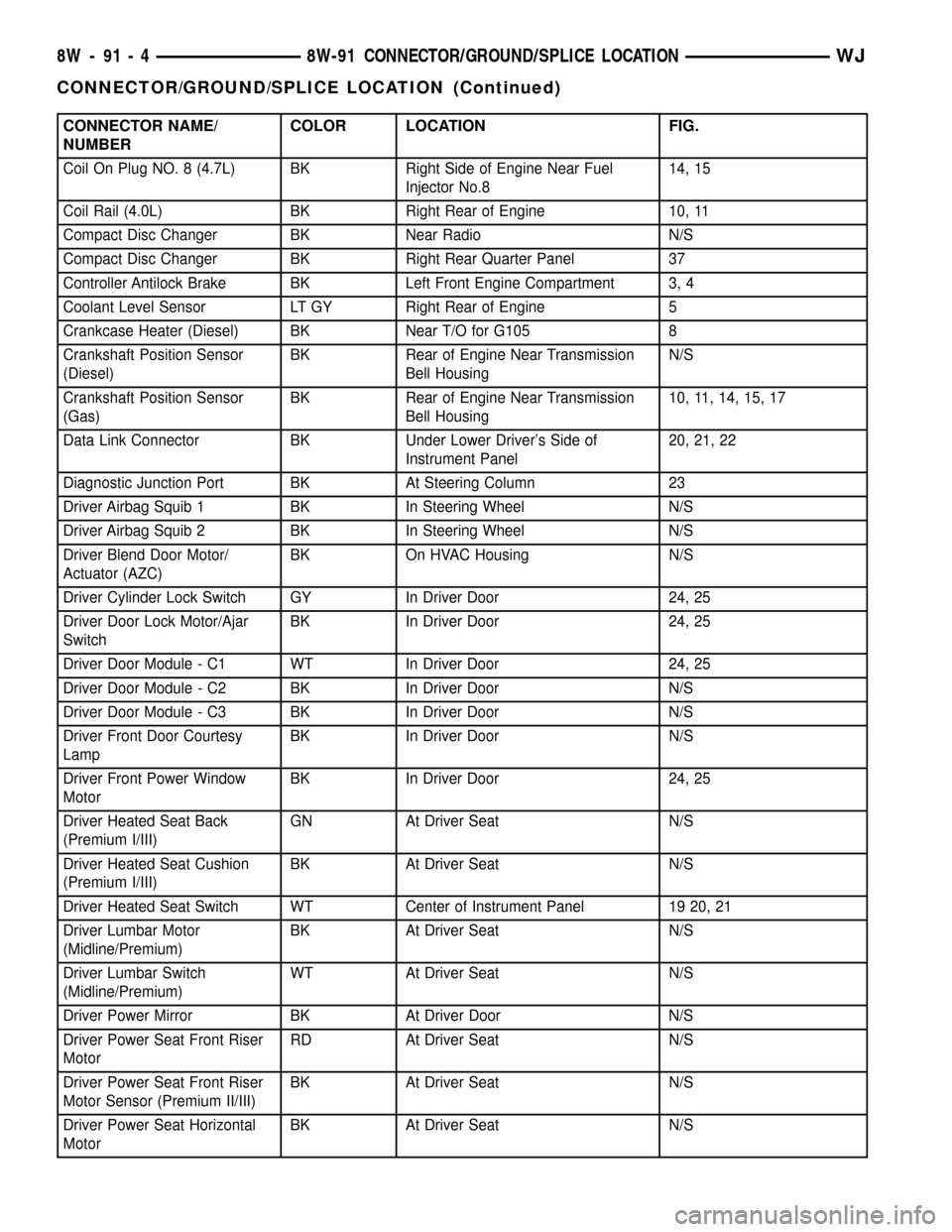
CONNECTOR NAME/
NUMBERCOLOR LOCATION FIG.
Coil On Plug NO. 8 (4.7L) BK Right Side of Engine Near Fuel
Injector No.814, 15
Coil Rail (4.0L) BK Right Rear of Engine 10, 11
Compact Disc Changer BK Near Radio N/S
Compact Disc Changer BK Right Rear Quarter Panel 37
Controller Antilock Brake BK Left Front Engine Compartment 3, 4
Coolant Level Sensor LT GY Right Rear of Engine 5
Crankcase Heater (Diesel) BK Near T/O for G105 8
Crankshaft Position Sensor
(Diesel)BK Rear of Engine Near Transmission
Bell HousingN/S
Crankshaft Position Sensor
(Gas)BK Rear of Engine Near Transmission
Bell Housing10, 11, 14, 15, 17
Data Link Connector BK Under Lower Driver's Side of
Instrument Panel20, 21, 22
Diagnostic Junction Port BK At Steering Column 23
Driver Airbag Squib 1 BK In Steering Wheel N/S
Driver Airbag Squib 2 BK In Steering Wheel N/S
Driver Blend Door Motor/
Actuator (AZC)BK On HVAC Housing N/S
Driver Cylinder Lock Switch GY In Driver Door 24, 25
Driver Door Lock Motor/Ajar
SwitchBK In Driver Door 24, 25
Driver Door Module - C1 WT In Driver Door 24, 25
Driver Door Module - C2 BK In Driver Door N/S
Driver Door Module - C3 BK In Driver Door N/S
Driver Front Door Courtesy
LampBK In Driver Door N/S
Driver Front Power Window
MotorBK In Driver Door 24, 25
Driver Heated Seat Back
(Premium I/III)GN At Driver Seat N/S
Driver Heated Seat Cushion
(Premium I/III)BK At Driver Seat N/S
Driver Heated Seat Switch WT Center of Instrument Panel 19 20, 21
Driver Lumbar Motor
(Midline/Premium)BK At Driver Seat N/S
Driver Lumbar Switch
(Midline/Premium)WT At Driver Seat N/S
Driver Power Mirror BK At Driver Door N/S
Driver Power Seat Front Riser
MotorRD At Driver Seat N/S
Driver Power Seat Front Riser
Motor Sensor (Premium II/III)BK At Driver Seat N/S
Driver Power Seat Horizontal
MotorBK At Driver Seat N/S
8W - 91 - 4 8W-91 CONNECTOR/GROUND/SPLICE LOCATIONWJ
CONNECTOR/GROUND/SPLICE LOCATION (Continued)
Page 1183 of 2199
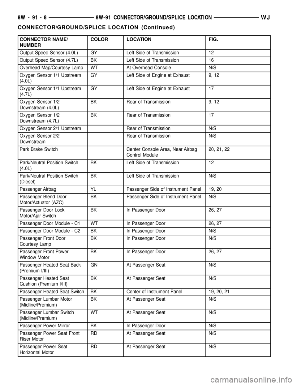
CONNECTOR NAME/
NUMBERCOLOR LOCATION FIG.
Output Speed Sensor (4.0L) GY Left Side of Transmission 12
Output Speed Sensor (4.7L) BK Left Side of Transmission 16
Overhead Map/Courtesy Lamp WT At Overhead Console N/S
Oxygen Sensor 1/1 Upstream
(4.0L)GY Left Side of Engine at Exhaust 9, 12
Oxygen Sensor 1/1 Upstream
(4.7L)GY Left Side of Engine at Exhaust 17
Oxygen Sensor 1/2
Downstream (4.0L)BK Rear of Transmission 9, 12
Oxygen Sensor 1/2
Downstream (4.7L)BK Rear of Transmission 17
Oxygen Sensor 2/1 Upstream Rear of Transmission N/S
Oxygen Sensor 2/2
DownstreamRear of Transmission N/S
Park Brake Switch Center Console Area, Near Airbag
Control Module20, 21, 22
Park/Neutral Position Switch
(4.0L)BK Left Side of Transmission 12
Park/Neutral Position Switch
(Diesel)BK Left Side of Transmission N/S
Passenger Airbag YL Passenger Side of Instrument Panel 19, 20
Passenger Blend Door
Motor/Actuator (AZC)BK Passenger Side of Instrument Panel N/S
Passenger Door Lock
Motor/Ajar SwitchBK In Passenger Door 26, 27
Passenger Door Module - C1 WT In Passenger Door 26, 27
Passenger Door Module - C2 BK In Passenger Door N/S
Passenger Front Door
Courtesy LampBK In Passenger Door N/S
Passenger Front Power
Window MotorBK In Passenger Door 26, 27
Passenger Heated Seat Back
(Premium I/III)GN At Passenger Seat N/S
Passenger Heated Seat
Cushion (Premium I/III)BK At Passenger Seat N/S
Passenger Heated Seat Switch BK Center of Instrument Panel 19, 20, 21
Passenger Lumbar Motor
(Midline/Premium)BK At Passenger Seat N/S
Passenger Lumbar Switch
(Midline/Premium)WT At Passenger Seat N/S
Passenger Power Mirror BK In Passenger Door N/S
Passenger Power Seat Front
Riser MotorRD At Passenger Seat N/S
Passenger Power Seat
Horizontal MotorRD At Passenger Seat N/S
8W - 91 - 8 8W-91 CONNECTOR/GROUND/SPLICE LOCATIONWJ
CONNECTOR/GROUND/SPLICE LOCATION (Continued)
Page 1579 of 2199

ACCUMULATOR
DESCRIPTION
The accumulator (Fig. 62) is a hydraulic device
that has the sole purpose of cushioning the applica-
tion of a band or clutch. The accumulator consists of
a dual-land piston and a spring located in a bore in
the transmission case. The 3-4 accumulator is located
in a housing attached to the side of the valve body
(Fig. 63).
OPERATION
Both the accumulator and the 3-4 accumulator
function the same. Line pressure is directed to the
small end of the piston when the transmission is
placed into a DRIVE position (Fig. 64), bottoming it
against the accumulator plate. When the 1-2 upshift
occurs (Fig. 65), line pressure is directed to the large
end of the piston and then to the kickdown servo. As
the line pressure reaches the accumulator, the com-
bination of spring pressure and line pressure forces
the piston away from the accumulator plate. This
causes a balanced pressure situation, which results
in a cushioned band application. After the kickdown
servo has become immovable, line pressure will fin-
ish pushing the accumulator up into its bore. When
the large end of the accumulator piston is seated in
its bore, the band or clutch is fully applied.
NOTE: The accumulator is shown in the inverted
position for illustrative purposes.
INSPECTION
Inspect the accumulator piston and seal rings (Fig.
66). Replace the seal rings if worn or cut. Replace the
piston if chipped or cracked.
Check condition of the accumulator inner and
outer springs (Fig. 66). Replace the springs if the
coils are cracked, distorted or collapsed.
Fig. 62 Accumulator
1 - ACCUMULATOR PISTON
2 - PISTON SPRING
Fig. 63 3-4 Accumulator and Housing
1 - ACCUMULATOR PISTON
2 - 3-4 ACCUMULATOR HOUSING
3 - TEFLON SEALS
4 - PISTON SPRING
5 - COVER PLATE AND SCREWS
Fig. 64 Accumulator in DRIVE - FIRST Gear Position
1 - LINE PRESSURE
21 - 60 AUTOMATIC TRANSMISSION - 42REWJ
Page 1593 of 2199

OPERATION
To apply the clutch, pressure is applied between
the clutch retainer and piston. The fluid pressure is
provided by the oil pump, transferred through the
control valves and passageways, and enters the
clutch through the hub of the reaction shaft support.
With pressure applied between the clutch retainer
and piston, the piston moves away from the clutch
retainer and compresses the clutch pack. This action
applies the clutch pack, allowing torque to flow
through the input shaft into the driving discs, and
into the clutch plates and pressure plate that are
lugged to the clutch retainer. The waved snap-ring is
used to cushion the application of the clutch pack.
When pressure is released from the piston, the
spring returns the piston to its fully released position
and disengages the clutch. The release spring also
helps to cushion the application of the clutch assem-
bly. When the clutch is in the process of being
released by the release spring, fluid flows through a
vent and one-way ball-check-valve located in the
clutch retainer. The check-valve is needed to elimi-
nate the possibility of plate drag caused by centrifu-
gal force acting on the residual fluid trapped in the
clutch piston retainer.
DISASSEMBLY
(1) Remove waved snap-ring and remove pressure
plate, clutch plates and clutch discs (Fig. 92).
(2) Compress clutch piston spring with Compressor
Tool C-3575-A (Fig. 93). Be sure legs of tool are
seated squarely on spring retainer before compress-
ing spring.
(3) Remove retainer snap-ring and remove com-
pressor tool.
(4) Remove spring retainer and clutch spring. Note
position of retainer on spring for assembly reference.
(5) Remove clutch piston from clutch retainer.
Remove piston by rotating it up and out of retainer.
(6) Remove seals from clutch retainer piston bore
and clutch retainer hub. Discard both seals as they
are not reusable.
INSPECTION
Inspect the front clutch components. Replace the
clutch discs if warped, worn, scored, burned or
charred, or if the facing is flaking off. Replace the
steel plates if heavily scored, warped, or broken. Be
sure the driving lugs on the plates are in good con-
dition. The lugs must not be bent, cracked or dam-
aged in any way.
Replace the clutch spring and spring retainer if
either is distorted, warped or broken.Check the lug grooves in the clutch retainer. The
steel plates should slide freely in the slots. Replace
the retainer if the grooves are worn or damaged.
Check action of the check ball in the retainer (Fig.
94). The ball must move freely and not stick.
NOTE: Inspect the clutch retainer bushings care-
fully (Fig. 95). The retainer bushings are NOT ser-
viceable. It will be necessary to replace the retainer
if either bushing is scored, or worn.
Inspect the piston and retainer seal surfaces for
nicks or scratches. Minor scratches can be removed
with crocus cloth. However, replace the piston and/or
retainer if the seal surfaces are seriously scored.
ASSEMBLY
NOTE: The 42RE transmission uses four plates and
discs for the front clutch.
(1) Soak clutch discs in transmission fluid while
assembling other clutch parts.
(2) Install new seals in the clutch retainer lower
groove and on outer diameter of the retainer hub. Be
sure lip of each seal faces interior of clutch retainer.
(3) Lubricate lips of the retainer seals with liberal
quantity of MopartDoor Ease. Then lubricate
retainer hub, bore and piston with light coat of trans-
mission fluid.
(4) Install clutch piston in retainer (Fig. 96). Use
twisting motion to seat piston in bottom of retainer.
CAUTION: Never push the clutch piston straight in.
This will fold the seals over causing leakage and
clutch slip.
(5) Position spring in clutch piston (Fig. 97).
(6) Position spring retainer on top of piston spring.
Make sure retainer is properly installed (Fig. 92).
(7) Compress piston spring and retainer with Com-
pressor Tool C-3575-A (Fig. 93). Then install new
snap-ring to secure spring retainer and spring.
(8) Install clutch plates and discs (Fig. 92). Install
steel plate then disc until all plates and discs are
installed. The front clutch uses 4 clutch discs and
plates in a 42RE transmission.
(9) Install pressure plate and waved snap-ring
(Fig. 92).
Clearance should be 1.70 to 3.40 mm (0.067 to
0.134 in.). If clearance is incorrect, clutch discs,
plates, pressure plates and snap-ring may have to be
changed.
21 - 74 AUTOMATIC TRANSMISSION - 42REWJ
FRONT CLUTCH (Continued)
Page 1877 of 2199
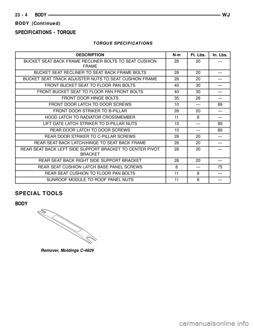
SPECIFICATIONS - TORQUE
TORQUE SPECIFICATIONS
DESCRIPTION N´m Ft. Lbs. In. Lbs.
BUCKET SEAT BACK FRAME RECLINER BOLTS TO SEAT CUSHION
FRAME28 20 Ð
BUCKET SEAT RECLINER TO SEAT BACK FRAME BOLTS 28 20 Ð
BUCKET SEAT TRACK ADJUSTER NUTS TO SEAT CUSHION FRAME 28 20 Ð
FRONT BUCKET SEAT TO FLOOR PAN BOLTS 40 30 Ð
FRONT BUCKET SEAT TO FLOOR PAN FRONT BOLTS 40 30 Ð
FRONT DOOR HINGE BOLTS 35 26 Ð
FRONT DOOR LATCH TO DOOR SCREWS 10 Ð 89
FRONT DOOR STRIKER TO B-PILLAR 28 20 Ð
HOOD LATCH TO RADIATOR CROSSMEMBER 11 8 Ð
LIFT GATE LATCH STRIKER TO D-PILLAR NUTS 10 Ð 89
REAR DOOR LATCH TO DOOR SCREWS 10 Ð 89
REAR DOOR STRIKER TO C-PILLAR SCREWS 28 20 Ð
REAR SEAT BACK LATCH/HINGE TO SEAT BACK FRAME 28 20 Ð
REAR SEAT BACK LEFT SIDE SUPPORT BRACKET TO CENTER PIVOT
BRACKET28 20 Ð
REAR SEAT BACK RIGHT SIDE SUPPORT BRACKET 28 20 Ð
REAR SEAT CUSHION LATCH BASE PANEL SCREWS 8 Ð 75
REAR SEAT CUSHION TO FLOOR PAN BOLTS 11 8 Ð
SUNROOF MODULE TO ROOF PANEL NUTS 11 8 Ð
SPECIAL TOOLS
BODY
Remover, Moldings C-4829
23 - 4 BODYWJ
BODY (Continued)