2002 JEEP GRAND CHEROKEE Fuel system
[x] Cancel search: Fuel systemPage 1300 of 2199

INSTALLATION
A gear-type oil pump is mounted at the underside
of the cylinder block opposite the No.4 main bearing.
(1) Install the oil pump on the cylinder block using
a replacement gasket. Tighten the bolts to 23 N´m
(17 ft. lbs.) torque.
(2) Install the oil pan (Refer to 9 - ENGINE/LU-
BRICATION/OIL PAN - INSTALLATION).
(3) Fill the oil pan with oil to the specified level.
INTAKE MANIFOLD
DESCRIPTION
The intake manifold (Fig. 83) is made of cast alu-
minum and uses eleven bolts to mount to the cylin-
der head. This mounting style improves sealing and
reduces the chance of leaks.
DIAGNOSIS AND TESTING - INTAKE
MANIFOLD LEAKAGE
An intake manifold air leak is characterized by
lower than normal manifold vacuum. Also, one or
more cylinders may not be functioning.
WARNING: USE EXTREME CAUTION WHEN THE
ENGINE IS OPERATING. DO NOT STAND IN A
DIRECT LINE WITH THE FAN. DO NOT PUT YOUR
HANDS NEAR THE PULLEYS, BELTS OR THE FAN.
DO NOT WEAR LOOSE CLOTHING.
(1) Start the engine.
(2) Spray a small stream of water at the suspected
leak area.
(3) If a change in RPM is observed the area of the
suspected leak has been found.
(4) Repair as required.
REMOVAL
NOTE: THE ENGINE INTAKE AND EXHAUST MANI-
FOLD MUST BE REMOVED AND INSTALLED
TOGETHER. THE MANIFOLDS USE A COMMON
GASKET AT THE CYLINDER HEAD.
(1) Disconnect the battery negative cable.
(2) Remove air cleaner inlet hose from the resona-
tor assembly.
(3) Remove the air cleaner assembly.
(4) Remove the throttle cable, vehicle speed control
cable (if equipped) and the transmission line pres-
sure cable (Refer to 21 - TRANSMISSION/TRANS-
AXLE/AUTOMATIC - AW4/THROTTLE VALVE
CABLE - REMOVAL).
(5) Disconnect the following electrical connections
and secure their harness out of the way:
²Throttle Position Sensor
²Idle Air Control Motor
²Coolant Temperature Sensor (at thermostat
housing)
²Intake Air Temperature Sensor
²Oxygen Sensor
²Crank Position Sensor
²Six (6) Fuel Injector Connectors
²Manifold Absolute Pressure (MAP) Sensor.
(6) Disconnect HVAC, and Brake Booster vacuum
supply hoses at the intake manifold.
(7) Perform the fuel pressure release procedure.
(Refer to 14 - FUEL SYSTEM/FUEL DELIVERY -
STANDARD PROCEDURE).
(8) Disconnect and remove the fuel system supply
line from the fuel rail assembly.
(9) Remove the accessory drive belt (Refer to 7 -
COOLING/ACCESSORY DRIVE/DRIVE BELTS -
REMOVAL).
(10) Remove the power steering pump from the
intake manifold and set aside.
(11) Raise the vehicle.
(12) Disconnect the exhaust pipes from the engine
exhaust manifolds.
(13) Lower the vehicle.
(14) Remove the intake manifold and exhaust
manifold bolts and manifolds (Fig. 84).
INSTALLATION
If the manifold is being replaced, ensure all the fit-
ting, etc. are transferred to the replacement mani-
fold.
(1) Install a new engine exhaust/intake manifold
gasket over the alignment dowels on the cylinder
head.
(2) Position the engine exhaust manifolds to the
cylinder head. Install fastener Number 3 and finger
tighten at this time (Fig. 84).
Fig. 83 Intake Manifold 4.0L Engine
WJENGINE - 4.0L 9 - 57
OIL PUMP (Continued)
Page 1301 of 2199
(3) Install intake manifold on the cylinder head
dowels.
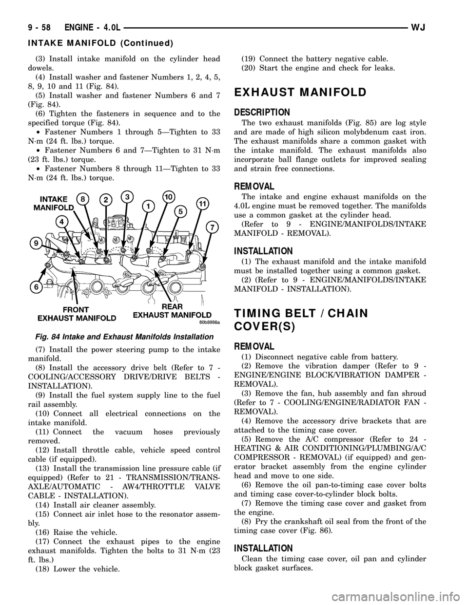
(4) Install washer and fastener Numbers 1, 2, 4, 5,
8, 9, 10 and 11 (Fig. 84).
(5) Install washer and fastener Numbers 6 and 7
(Fig. 84).
(6) Tighten the fasteners in sequence and to the
specified torque (Fig. 84).
²Fastener Numbers 1 through 5ÐTighten to 33
N´m (24 ft. lbs.) torque.
²Fastener Numbers 6 and 7ÐTighten to 31 N´m
(23 ft. lbs.) torque.
²Fastener Numbers 8 through 11ÐTighten to 33
N´m (24 ft. lbs.) torque.
(7) Install the power steering pump to the intake
manifold.
(8) Install the accessory drive belt (Refer to 7 -
COOLING/ACCESSORY DRIVE/DRIVE BELTS -
INSTALLATION).
(9) Install the fuel system supply line to the fuel
rail assembly.
(10) Connect all electrical connections on the
intake manifold.
(11) Connect the vacuum hoses previously
removed.
(12) Install throttle cable, vehicle speed control
cable (if equipped).
(13) Install the transmission line pressure cable (if
equipped) (Refer to 21 - TRANSMISSION/TRANS-
AXLE/AUTOMATIC - AW4/THROTTLE VALVE
CABLE - INSTALLATION).
(14) Install air cleaner assembly.
(15) Connect air inlet hose to the resonator assem-
bly.
(16) Raise the vehicle.
(17) Connect the exhaust pipes to the engine
exhaust manifolds. Tighten the bolts to 31 N´m (23
ft. lbs.)
(18) Lower the vehicle.(19) Connect the battery negative cable.
(20) Start the engine and check for leaks.
EXHAUST MANIFOLD
DESCRIPTION
The two exhaust manifolds (Fig. 85) are log style
and are made of high silicon molybdenum cast iron.
The exhaust manifolds share a common gasket with
the intake manifold. The exhaust manifolds also
incorporate ball flange outlets for improved sealing
and strain free connections.
REMOVAL
The intake and engine exhaust manifolds on the
4.0L engine must be removed together. The manifolds
use a common gasket at the cylinder head.
(Refer to 9 - ENGINE/MANIFOLDS/INTAKE
MANIFOLD - REMOVAL).
INSTALLATION
(1) The exhaust manifold and the intake manifold
must be installed together using a common gasket.
(2) (Refer to 9 - ENGINE/MANIFOLDS/INTAKE
MANIFOLD - INSTALLATION).
TIMING BELT / CHAIN
COVER(S)
REMOVAL
(1) Disconnect negative cable from battery.
(2) Remove the vibration damper (Refer to 9 -
ENGINE/ENGINE BLOCK/VIBRATION DAMPER -
REMOVAL).
(3) Remove the fan, hub assembly and fan shroud
(Refer to 7 - COOLING/ENGINE/RADIATOR FAN -
REMOVAL).
(4) Remove the accessory drive brackets that are
attached to the timing case cover.
(5) Remove the A/C compressor (Refer to 24 -
HEATING & AIR CONDITIONING/PLUMBING/A/C
COMPRESSOR - REMOVAL) (if equipped) and gen-
erator bracket assembly from the engine cylinder
head and move to one side.
(6) Remove the oil pan-to-timing case cover bolts
and timing case cover-to-cylinder block bolts.
(7) Remove the timing case cover and gasket from
the engine.
(8) Pry the crankshaft oil seal from the front of the
timing case cover (Fig. 86).
INSTALLATION
Clean the timing case cover, oil pan and cylinder
block gasket surfaces.
Fig. 84 Intake and Exhaust Manifolds Installation
9 - 58 ENGINE - 4.0LWJ
INTAKE MANIFOLD (Continued)
Page 1307 of 2199
DIAGNOSIS AND TESTING
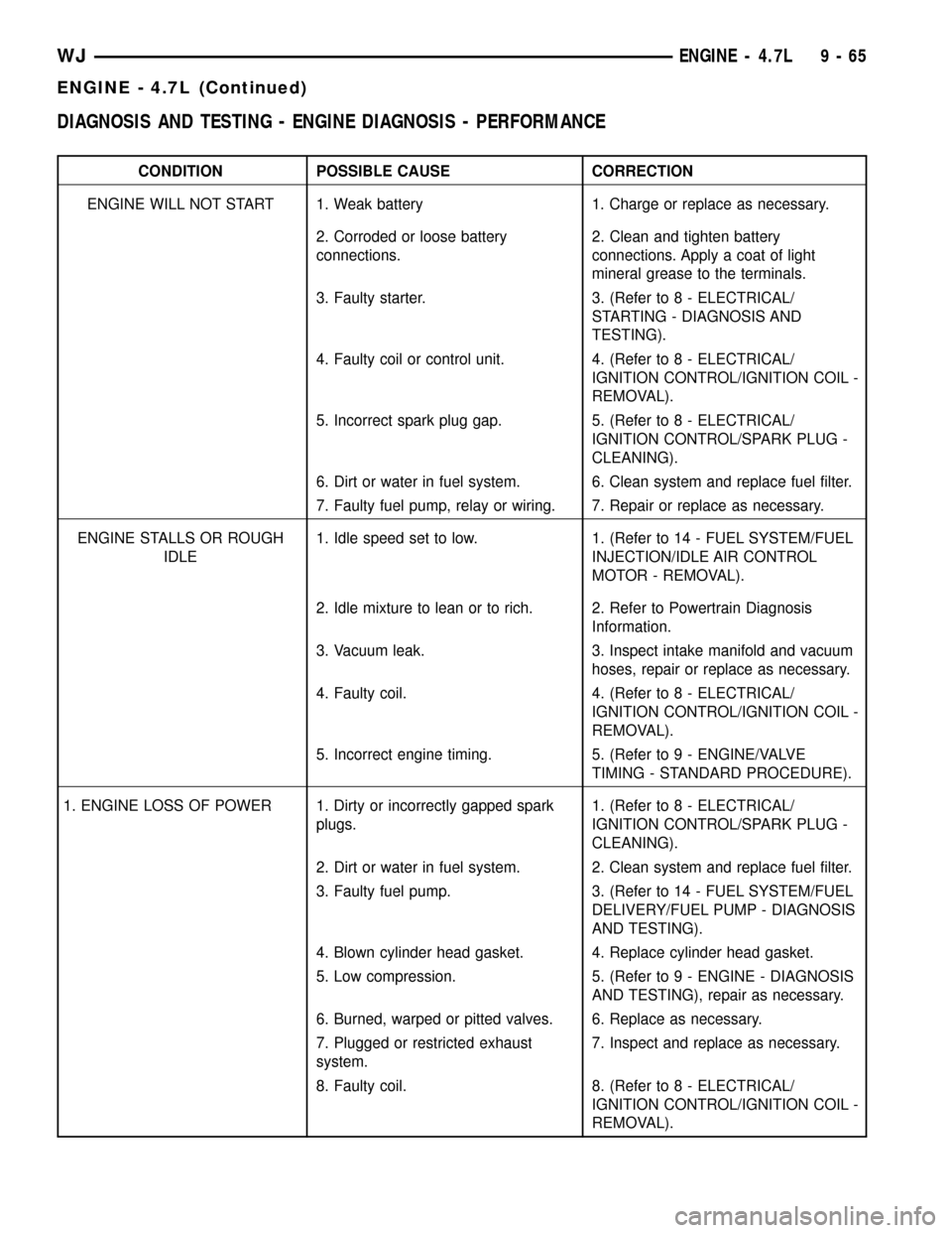
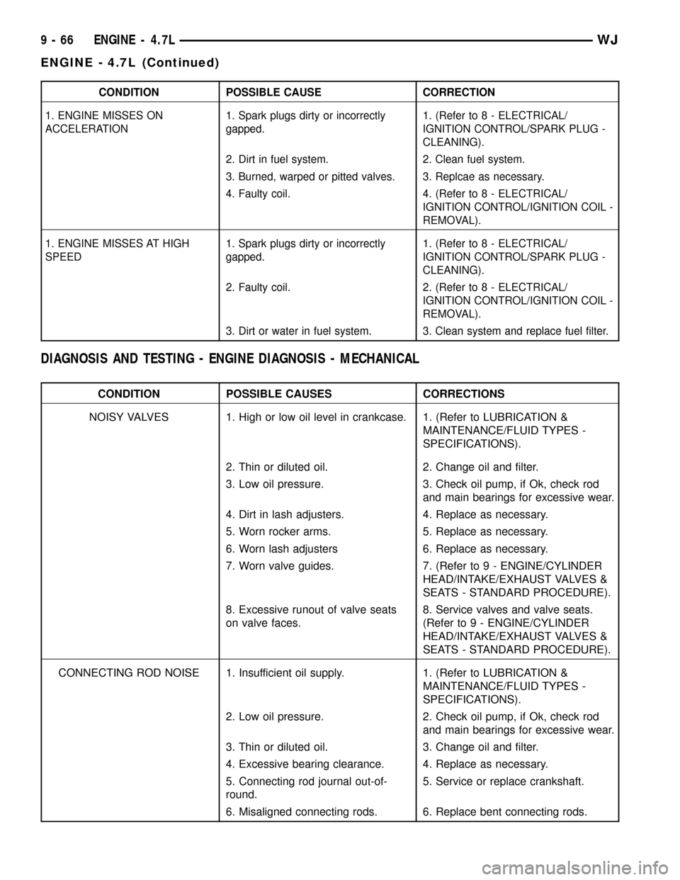
DIAGNOSIS AND TESTING - ENGINE
DIAGNOSIS - INTRODUCTION
Engine diagnosis is helpful in determining the
causes of malfunctions not detected and remedied by
routine maintenance.
These malfunctions may be classified as either per-
formance (e.g., engine idles rough and stalls) or
mechanical (e.g., a strange noise).
(Refer to 9 - ENGINE - DIAGNOSIS AND TEST-
ING)ÐPERFORMANCE and (Refer to 9 - ENGINE -
DIAGNOSIS AND TESTING)ÐMECHANICAL for
possible causes and corrections of malfunctions.
(Refer to 14 - FUEL SYSTEM/FUEL DELIVERY -
DIAGNOSIS AND TESTING) and (Refer to 14 -
FUEL SYSTEM/FUEL INJECTION - DIAGNOSIS
AND TESTING) for the fuel system diagnosis.
Additional tests and diagnostic procedures may be
necessary for specific engine malfunctions that can
not be isolated with the Service Diagnosis charts.
Information concerning additional tests and diagno-
sis is provided within the following diagnosis:
²Cylinder Compression Pressure Test (Refer to 9 -
ENGINE - DIAGNOSIS AND TESTING).
²Cylinder Combustion Pressure Leakage Test
(Refer to 9 - ENGINE - DIAGNOSIS AND TEST-
ING).
²Engine Cylinder Head Gasket Failure Diagnosis
(Refer to 9 - ENGINE/CYLINDER HEAD - DIAGNO-
SIS AND TESTING).
²Intake Manifold Leakage Diagnosis (Refer to 9 -
ENGINE/MANIFOLDS/INTAKE MANIFOLD -
DIAGNOSIS AND TESTING).
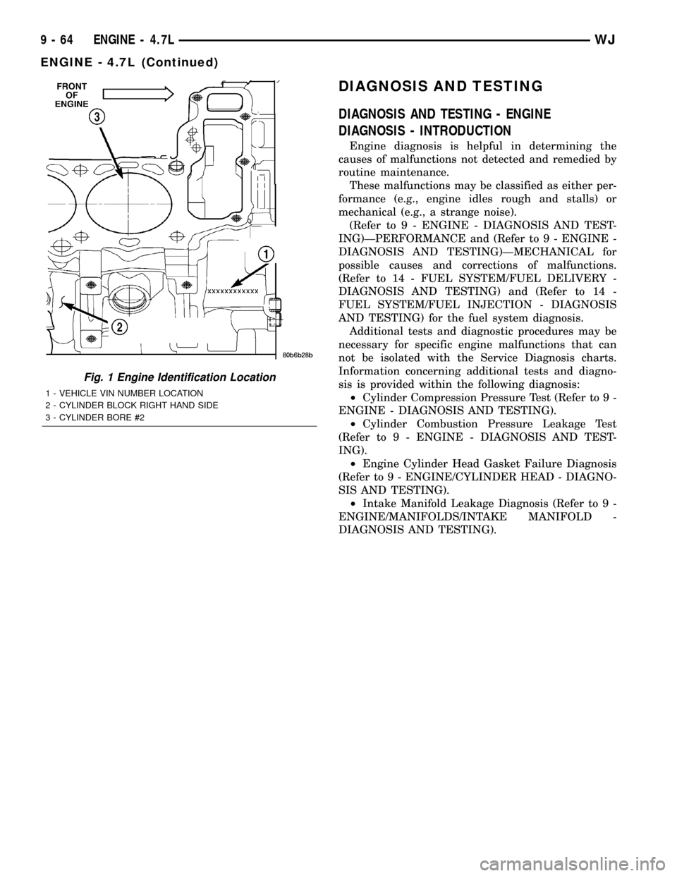
Fig. 1 Engine Identification Location
1 - VEHICLE VIN NUMBER LOCATION
2 - CYLINDER BLOCK RIGHT HAND SIDE
3 - CYLINDER BORE #2
9 - 64 ENGINE - 4.7LWJ
ENGINE - 4.7L (Continued)
Page 1308 of 2199
DIAGNOSIS AND TESTING - ENGINE DIAGNOSIS - PERFORMANCE
CONDITION POSSIBLE CAUSE CORRECTION
ENGINE WILL NOT START 1. Weak battery 1. Charge or replace as necessary.
2. Corroded or loose battery
connections.2. Clean and tighten battery
connections. Apply a coat of light
mineral grease to the terminals.
3. Faulty starter. 3. (Refer to 8 - ELECTRICAL/
STARTING - DIAGNOSIS AND
TESTING).
4. Faulty coil or control unit. 4. (Refer to 8 - ELECTRICAL/
IGNITION CONTROL/IGNITION COIL -
REMOVAL).
5. Incorrect spark plug gap. 5. (Refer to 8 - ELECTRICAL/
IGNITION CONTROL/SPARK PLUG -
CLEANING).
6. Dirt or water in fuel system. 6. Clean system and replace fuel filter.
7. Faulty fuel pump, relay or wiring. 7. Repair or replace as necessary.
ENGINE STALLS OR ROUGH
IDLE1. Idle speed set to low. 1. (Refer to 14 - FUEL SYSTEM/FUEL
INJECTION/IDLE AIR CONTROL
MOTOR - REMOVAL).
2. Idle mixture to lean or to rich. 2. Refer to Powertrain Diagnosis
Information.
3. Vacuum leak. 3. Inspect intake manifold and vacuum
hoses, repair or replace as necessary.
4. Faulty coil. 4. (Refer to 8 - ELECTRICAL/
IGNITION CONTROL/IGNITION COIL -
REMOVAL).
5. Incorrect engine timing. 5. (Refer to 9 - ENGINE/VALVE
TIMING - STANDARD PROCEDURE).
1. ENGINE LOSS OF POWER 1. Dirty or incorrectly gapped spark
plugs.1. (Refer to 8 - ELECTRICAL/
IGNITION CONTROL/SPARK PLUG -
CLEANING).
2. Dirt or water in fuel system. 2. Clean system and replace fuel filter.
3. Faulty fuel pump. 3. (Refer to 14 - FUEL SYSTEM/FUEL
DELIVERY/FUEL PUMP - DIAGNOSIS
AND TESTING).
4. Blown cylinder head gasket. 4. Replace cylinder head gasket.
5. Low compression. 5. (Refer to 9 - ENGINE - DIAGNOSIS
AND TESTING), repair as necessary.
6. Burned, warped or pitted valves. 6. Replace as necessary.
7. Plugged or restricted exhaust
system.7. Inspect and replace as necessary.
8. Faulty coil. 8. (Refer to 8 - ELECTRICAL/
IGNITION CONTROL/IGNITION COIL -
REMOVAL).
WJENGINE - 4.7L 9 - 65
ENGINE - 4.7L (Continued)
Page 1309 of 2199
CONDITION POSSIBLE CAUSE CORRECTION
1. ENGINE MISSES ON
ACCELERATION1. Spark plugs dirty or incorrectly
gapped.1. (Refer to 8 - ELECTRICAL/
IGNITION CONTROL/SPARK PLUG -
CLEANING).
2. Dirt in fuel system. 2. Clean fuel system.
3. Burned, warped or pitted valves. 3. Replcae as necessary.
4. Faulty coil. 4. (Refer to 8 - ELECTRICAL/
IGNITION CONTROL/IGNITION COIL -
REMOVAL).
1. ENGINE MISSES AT HIGH
SPEED1. Spark plugs dirty or incorrectly
gapped.1. (Refer to 8 - ELECTRICAL/
IGNITION CONTROL/SPARK PLUG -
CLEANING).
2. Faulty coil. 2. (Refer to 8 - ELECTRICAL/
IGNITION CONTROL/IGNITION COIL -
REMOVAL).
3. Dirt or water in fuel system. 3. Clean system and replace fuel filter.
DIAGNOSIS AND TESTING - ENGINE DIAGNOSIS - MECHANICAL
CONDITION POSSIBLE CAUSES CORRECTIONS
NOISY VALVES 1. High or low oil level in crankcase. 1. (Refer to LUBRICATION &
MAINTENANCE/FLUID TYPES -
SPECIFICATIONS).
2. Thin or diluted oil. 2. Change oil and filter.
3. Low oil pressure. 3. Check oil pump, if Ok, check rod
and main bearings for excessive wear.
4. Dirt in lash adjusters. 4. Replace as necessary.
5. Worn rocker arms. 5. Replace as necessary.
6. Worn lash adjusters 6. Replace as necessary.
7. Worn valve guides. 7. (Refer to 9 - ENGINE/CYLINDER
HEAD/INTAKE/EXHAUST VALVES &
SEATS - STANDARD PROCEDURE).
8. Excessive runout of valve seats
on valve faces.8. Service valves and valve seats.
(Refer to 9 - ENGINE/CYLINDER
HEAD/INTAKE/EXHAUST VALVES &
SEATS - STANDARD PROCEDURE).
CONNECTING ROD NOISE 1. Insufficient oil supply. 1. (Refer to LUBRICATION &
MAINTENANCE/FLUID TYPES -
SPECIFICATIONS).
2. Low oil pressure. 2. Check oil pump, if Ok, check rod
and main bearings for excessive wear.
3. Thin or diluted oil. 3. Change oil and filter.
4. Excessive bearing clearance. 4. Replace as necessary.
5. Connecting rod journal out-of-
round.5. Service or replace crankshaft.
6. Misaligned connecting rods. 6. Replace bent connecting rods.
9 - 66 ENGINE - 4.7LWJ
ENGINE - 4.7L (Continued)
Page 1311 of 2199
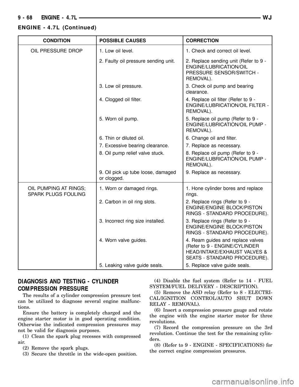
CONDITION POSSIBLE CAUSES CORRECTION
OIL PRESSURE DROP 1. Low oil level. 1. Check and correct oil level.
2. Faulty oil pressure sending unit. 2. Replace sending unit (Refer to 9 -
ENGINE/LUBRICATION/OIL
PRESSURE SENSOR/SWITCH -
REMOVAL).
3. Low oil pressure. 3. Check oil pump and bearing
clearance.
4. Clogged oil filter. 4. Replace oil filter (Refer to 9 -
ENGINE/LUBRICATION/OIL FILTER -
REMOVAL).
5. Worn oil pump. 5. Replace oil pump (Refer to 9 -
ENGINE/LUBRICATION/OIL PUMP -
REMOVAL).
6. Thin or diluted oil. 6. Change oil and filter.
7. Excessive bearing clearance. 7. Replace as necessary.
8. Oil pump relief valve stuck. 8. Replace oil pump (Refer to 9 -
ENGINE/LUBRICATION/OIL PUMP -
REMOVAL).
9. Oil pick up tube loose, damaged
or clogged.9. Replace as necessary.
OIL PUMPING AT RINGS;
SPARK PLUGS FOULING1. Worn or damaged rings. 1. Hone cylinder bores and replace
rings.
2. Carbon in oil ring slots. 2. Replace rings (Refer to 9 -
ENGINE/ENGINE BLOCK/PISTON
RINGS - STANDARD PROCEDURE).
3. Incorrect ring size installed. 3. Replace rings (Refer to 9 -
ENGINE/ENGINE BLOCK/PISTON
RINGS - STANDARD PROCEDURE).
4. Worn valve guides. 4. Ream guides and replace valves
(Refer to 9 - ENGINE/CYLINDER
HEAD/INTAKE/EXHAUST VALVES &
SEATS - STANDARD PROCEDURE).
5. Leaking valve guide seals. 5. Replace valve guide seals.
DIAGNOSIS AND TESTING - CYLINDER
COMPRESSION PRESSURE
The results of a cylinder compression pressure test
can be utilized to diagnose several engine malfunc-
tions.
Ensure the battery is completely charged and the
engine starter motor is in good operating condition.
Otherwise the indicated compression pressures may
not be valid for diagnosis purposes.
(1) Clean the spark plug recesses with compressed
air.
(2) Remove the spark plugs.
(3) Secure the throttle in the wide-open position.(4) Disable the fuel system (Refer to 14 - FUEL
SYSTEM/FUEL DELIVERY - DESCRIPTION).
(5) Remove the ASD relay (Refer to 8 - ELECTRI-
CAL/IGNITION CONTROL/AUTO SHUT DOWN
RELAY - REMOVAL).
(6) Insert a compression pressure gauge and rotate
the engine with the engine starter motor for three
revolutions.
(7) Record the compression pressure on the 3rd
revolution. Continue the test for the remaining cylin-
ders.
(8) (Refer to 9 - ENGINE - SPECIFICATIONS) for
the correct engine compression pressures.
9 - 68 ENGINE - 4.7LWJ
ENGINE - 4.7L (Continued)
Page 1315 of 2199

(13) Disconnect the engine block heater power
cable from the block heater.
(14) Lower vehicle.
(15) Remove throttle body resonator assembly and
inlet hose.
(16) Disconnect throttle and speed control cables.
(17) Disconnect tube from both the left and right
side crankcase breathers, then remove the breathers
(Fig. 5).
(18) Discharge A/C system (Refer to 24 - HEAT-
ING & AIR CONDITIONING/PLUMBING - STAN-
DARD PROCEDURE).(19) Remove radiator fan (Refer to 7 - COOLING/
ENGINE/RADIATOR FAN - REMOVAL) and acces-
sory drive belt (Refer to 7 - COOLING/ACCESSORY
DRIVE/DRIVE BELTS - REMOVAL).
(20) Remove A/C compressor (Refer to 24 - HEAT-
ING & AIR CONDITIONING/PLUMBING/A/C COM-
PRESSOR - REMOVAL).
(21) Disconnect transmission oil cooler lines at the
radiator.
(22) Disconnect radiator lower hose at the thermo-
stat housing.
(23) Remove A/C condenser (Refer to 24 - HEAT-
ING & AIR CONDITIONING/PLUMBING/A/C CON-
DENSER - REMOVAL).
(24) Remove radiator (Refer to 7 - COOLING/EN-
GINE/RADIATOR - REMOVAL).
(25) Remove generator (Refer to 8 - ELECTRICAL/
CHARGING/GENERATOR - REMOVAL).
(26) Disconnect the two heater hoses from the tim-
ing chain cover.
(27) Disconnect engine harness at the following
points :
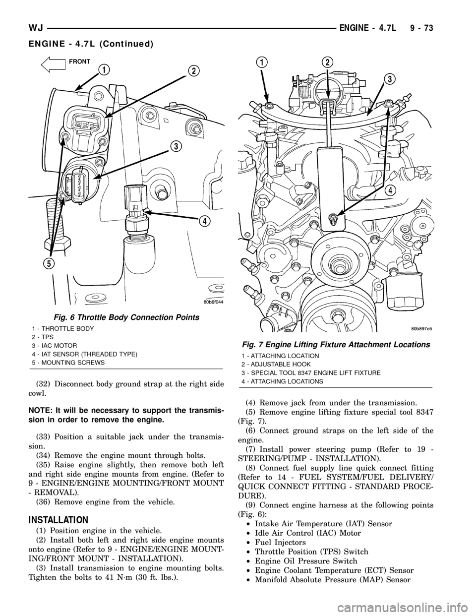
²Intake air temperature (IAT) sensor (Fig. 6)
²Fuel Injectors
²Throttle Position (TPS) Switch
²Idle Air Control (IAC) Motor
²Engine Oil Pressure Switch
²Engine Coolant Temperature (ECT) Sensor
²Manifold absolute pressure (MAP) Sensor
²Camshaft Position (CMP) Sensor
²Coil Over Plugs
(28) Release fuel rail pressure (Refer to 14 - FUEL
SYSTEM/FUEL DELIVERY - STANDARD PROCE-
DURE) then disconnect the fuel supply quick connect
fitting at the fuel rail (Refer to 14 - FUEL SYSTEM/
FUEL DELIVERY/QUICK CONNECT FITTING -
STANDARD PROCEDURE).
(29) Remove power steering pump and position out
of the way.
(30) Disconnect ground straps from the left side of
the engine.
(31) Install Engine Lifting Fixture Special Tool
8347 (Fig. 7)following these steps.
²Holding the lifting fixture at a slight angle, slide
the large bore in the front plate over the hex portion
of the lifting stud.
²Position the two remaining fixture arms onto
the two lifting studs in the cylinder heads.
²Pull foward and upward on the lifting fixture so
that the lifting stud rest in the slotted area below the
large bore.
²Secure the lifting fixture to the three studs
using three 7/16 ± 14 N/C locknuts.
²Make sure the lifting loop in the lifting fixture is
in the last hole (closest to the throttle body) to min-
imize the angle of engine during removal.
Fig. 4 Crankshaft Position Sensor
1 - CRANKSHAFT POSITION SENSOR
2 - CYLINDER HEAD COVER
3 - CAMSHAFT POSITION SENSOR
4 - RIGHT SIDE CYLINDER BLOCK
Fig. 5 Crankcase Breather Connection Points
1 - CRANKCASE BREATHERS
9 - 72 ENGINE - 4.7LWJ
ENGINE - 4.7L (Continued)
Page 1316 of 2199
(32) Disconnect body ground strap at the right side
cowl.
NOTE: It will be necessary to support the transmis-
sion in order to remove the engine.
(33) Position a suitable jack under the transmis-
sion.
(34) Remove the engine mount through bolts.
(35) Raise engine slightly, then remove both left
and right side engine mounts from engine. (Refer to
9 - ENGINE/ENGINE MOUNTING/FRONT MOUNT
- REMOVAL).
(36) Remove engine from the vehicle.
INSTALLATION
(1) Position engine in the vehicle.
(2) Install both left and right side engine mounts
onto engine (Refer to 9 - ENGINE/ENGINE MOUNT-
ING/FRONT MOUNT - INSTALLATION).
(3) Install transmission to engine mounting bolts.
Tighten the bolts to 41 N´m (30 ft. lbs.).(4) Remove jack from under the transmission.
(5) Remove engine lifting fixture special tool 8347
(Fig. 7).
(6) Connect ground straps on the left side of the
engine.
(7) Install power steering pump (Refer to 19 -
STEERING/PUMP - INSTALLATION).
(8) Connect fuel supply line quick connect fitting
(Refer to 14 - FUEL SYSTEM/FUEL DELIVERY/
QUICK CONNECT FITTING - STANDARD PROCE-
DURE).
(9) Connect engine harness at the following points
(Fig. 6):
²Intake Air Temperature (IAT) Sensor
²Idle Air Control (IAC) Motor
²Fuel Injectors
²Throttle Position (TPS) Switch
²Engine Oil Pressure Switch
²Engine Coolant Temperature (ECT) Sensor
²Manifold Absolute Pressure (MAP) Sensor
Fig. 6 Throttle Body Connection Points
1 - THROTTLE BODY
2 - TPS
3 - IAC MOTOR
4 - IAT SENSOR (THREADED TYPE)
5 - MOUNTING SCREWS
Fig. 7 Engine Lifting Fixture Attachment Locations
1 - ATTACHING LOCATION
2 - ADJUSTABLE HOOK
3 - SPECIAL TOOL 8347 ENGINE LIFT FIXTURE
4 - ATTACHING LOCATIONS
WJENGINE - 4.7L 9 - 73
ENGINE - 4.7L (Continued)