2002 JEEP GRAND CHEROKEE four wheel
[x] Cancel search: four wheelPage 610 of 2199

²Front Check Valve- The front washer system
check valve is integral to the wye fitting located in
the washer plumbing between the cowl plenum
washer hose and the front washer nozzles, and is
concealed beneath the cowl plenum cover/grille panel
at the base of the windshield.
²Front Washer Nozzle- Two fluidic front
washer nozzles are secured with integral snap fea-
tures to dedicated openings in the cowl plenum cover/
grille panel located near the base of the windshield.
²Front Washer Plumbing- The plumbing for
the front washer system consists of rubber hoses and
molded plastic fittings. The plumbing is routed along
the left side of the engine compartment from the
washer reservoir, and through the dash panel into
the cowl plenum to the front washer nozzle fittings
beneath the cowl plenum cover/grille panel.
²Front Washer Pump/Motor- The front washer
pump/motor unit is located in a dedicated hole on the
lower outboard side of the washer reservoir, behind
the inner fender liner ahead of the left front wheel.
The front washer pump is located ahead of and below
the rear washer pump.
²Front Wiper Arm- The two front wiper arms
are secured with nuts to the threaded studs on the
ends of the two wiper pivot shafts, which extend
through the cowl plenum cover/grille panel located
near the base of the windshield.
²Front Wiper Blade- The two front wiper
blades are secured to the two front wiper arms with
an integral latch, and are parked on the glass near
the bottom of the windshield when the front wiper
system is not in operation.
²Front Wiper Module- The front wiper pivot
shafts are the only visible components of the front
wiper module. The remainder of the module is con-
cealed within the cowl plenum beneath the cowl ple-
num cover/grille panel. The front wiper module
includes the module bracket, four rubber-isolated
wiper module mounts, the front wiper motor, the
wiper motor crank arm, the two wiper drive links,
and the two front wiper pivots.
²Rain Sensor Module- Models equipped with
the optional automatic wiper feature have a Rain
Sensor Module (RSM) located behind a trim cover on
a bracket bonded to the inside surface of the wind-
shield glass, just above the inside rear view mirror
mounting button.
²Right Multi-Function Switch- The right
(wiper) multi-function switch is secured to the right
side of the multi-function switch mounting housing
near the top of the steering column, just below the
steering wheel. Only the control stalk for the right
multi-function switch is visible, while the remainder
of the switch is concealed beneath the steering col-
umn shrouds. The right multi-function switch con-tains all of the switches and control circuitry for both
the front and rear wiper and washer systems.
²Washer Fluid Level Switch- The washer fluid
level switch is located in a dedicated hole near the
center of the forward surface of the washer reservoir,
behind the left front wheel house splash shield.
²Washer Reservoir- The washer reservoir is
concealed between the left inner fender shield and
the left outer fender panel, behind the inner fender
liner and ahead of the left front wheel. The washer
reservoir filler neck is the only visible portion of the
reservoir, and it is accessed from the left front corner
of the engine compartment.
²Wiper High-Low Relay- The wiper high-low
relay is an International Standards Organization
(ISO) micro relay located in the Power Distribution
Center (PDC) in the engine compartment near the
battery.
²Wiper On-Off Relay- The wiper on-off relay is
an International Standards Organization (ISO) micro
relay located in the Power Distribution Center (PDC)
in the engine compartment near the battery.
Hard wired circuitry connects the front wiper and
washer system components to the electrical system of
the vehicle. These hard wired circuits are integral to
several wire harnesses, which are routed throughout
the vehicle and retained by many different methods.
These circuits may be connected to each other, to the
vehicle electrical system and to the front wiper and
washer system components through the use of a com-
bination of soldered splices, splice block connectors,
and many different types of wire harness terminal
connectors and insulators. Refer to the appropriate
wiring information. The wiring information includes
wiring diagrams, proper wire and connector repair
procedures, further details on wire harness routing
and retention, as well as pin-out and location views
for the various wire harness connectors, splices and
grounds.
OPERATING MODES
The components of the front wiper and washer sys-
tem are designed to work in concert to provide the
following operating modes:
²Automatic Wiper- In models equipped with
the optional automatic wiper feature, the internal
circuitry of both the right (wiper) multi-function
switch, the rain sensor module, and the BCM work
in concert to provide an automatic wiper mode with
five sensitivity selections. The BCM tells the Rain
Sensor Module (RSM) when the automatic wiper
mode is selected and the manually selected sensitiv-
ity level, then the rain sensor module tells the BCM
each time enough water droplets have accumulated
within the wipe pattern on the windshield to require
front wiper operation. The BCM then automatically
WJFRONT WIPERS/WASHERS 8R - 3
FRONT WIPERS/WASHERS (Continued)
Page 642 of 2199

stalk is moved to the rear Wash position, the Wash
position circuitry within the switch directs battery
current to the rear washer pump/motor unit, and to
both the rear wiper motor control and rear washer
switch output signal inputs of the rear wiper module
electronic circuitry, which causes the wiper motor to
run at a fixed cycle for as long as the Wash mode is
selected plus about three additional fixed wipe cycles.
The rear wiper module electronic circuitry controls
the switching of battery current to the rear wiper
motor brush, which controls wiper motor operation.
The intermittent wipe and wipe-after-wash features
of the rear wiper and washer system are both pro-
vided by the rear wiper module electronic circuitry.
The rear wiper module electronic circuitry also mon-
itors the liftgate flip-up glass ajar switch and will
park the rear wiper blade off of the glass any time it
senses that the liftgate flip-up glass is ajar, the igni-
tion switch is turned to the Off position, or the right
multi-function switch control sleeve is moved to the
Off position. This feature ensures that the rear wiper
blade will not interfere with or be damaged by the
operation of the liftgate flip-up glass. However, if the
ignition switch is turned to the Off position or the
liftgate flip-up glass is opened while the rear wiper is
operating, the right multi-function switch control
sleeve must be cycled to the Off position and back to
the On or Delay position after the ignition switch is
turned back On or the liftgate flip-up glass is closed
before the rear wiper will operate again.
Refer to the owner's manual in the vehicle glove
box for more information on the features and opera-
tion of the rear wiper and washer system.
DIAGNOSIS AND TESTING - REAR WIPER &
WASHER SYSTEM
WIPER SYSTEM
The diagnosis found here addresses an electrically
inoperative rear wiper system. If the rear wiper
motor operates, but the wiper does not move on the
liftgate glass, replace the faulty rear wiper module. If
the wiper operates, but chatters, lifts, or does not
clear the glass, clean and inspect the wiper system
components as required. (Refer to 8 - ELECTRICAL/
REAR WIPERS/WASHERS - INSPECTION) and
(Refer to 8 - ELECTRICAL/REAR WIPERS/WASH-
ERS - CLEANING). Refer to the appropriate wiring
information. The wiring information includes wiring
diagrams, proper wire and connector repair proce-
dures, details of wire harness routing and retention,
connector pin-out information and location views for
the various wire harness connectors, splices and
grounds.WARNING: ON VEHICLES EQUIPPED WITH AIR-
BAGS, DISABLE THE AIRBAG SYSTEM BEFORE
ATTEMPTING ANY STEERING WHEEL, STEERING
COLUMN, OR INSTRUMENT PANEL COMPONENT
DIAGNOSIS OR SERVICE. DISCONNECT AND ISO-
LATE THE BATTERY NEGATIVE (GROUND) CABLE,
THEN WAIT TWO MINUTES FOR THE AIRBAG SYS-
TEM CAPACITOR TO DISCHARGE BEFORE PER-
FORMING FURTHER DIAGNOSIS OR SERVICE. THIS
IS THE ONLY SURE WAY TO DISABLE THE AIRBAG
SYSTEM. FAILURE TO TAKE THE PROPER PRE-
CAUTIONS COULD RESULT IN ACCIDENTAL AIR-
BAG DEPLOYMENT AND POSSIBLE PERSONAL
INJURY.
(1) Check that the interior lighting switch on the
control stalk of the left multi-function switch is not
in the dome lamp disable position. With all four
doors and the liftgate closed, open the liftgate flip-up
glass. The interior lamps should light. If not, depress
the cargo lamp lens to actuate the cargo lamp defeat
switch and the interior lamps should light. Close all
four doors, the liftgate and the liftgate flip-up glass.
Note whether the interior lamps remain lighted.
They should turn off after about thirty seconds. If
OK, go to Step 2. If not OK, go to Step 9.
(2) Check the fused B(+) fuse (Fuse8-15ampere)
in the Junction Block (JB). If OK, go to Step 3. If not
OK, repair the shorted circuit or component as
required and replace the faulty fuse.
(3) Check for battery voltage at the fused B(+) fuse
(Fuse8-15ampere) in the JB. If OK, go to Step 4. If
not OK, repair the open fused B(+) circuit between
the JB and the Power Distribution Center (PDC) as
required.
(4) Check the fused ignition switch output (run-
acc) fuse (Fuse 29 - 10 ampere) in the JB. If OK, go
to Step 5. If not OK, repair the shorted circuit or
component as required and replace the faulty fuse.
(5) Turn the ignition switch to the On position.
Check for battery voltage at the fused ignition switch
output (run-acc) fuse (Fuse 29 - 10 ampere) in the
JB. If OK, turn the ignition switch to the Off position
and go to Step 6. If not OK, repair the open fused
ignition switch output (run-acc) circuit between the
JB and the ignition switch as required.
(6) Disconnect and isolate the battery negative
cable. Disconnect the instrument panel wire harness
connector for the right multi-function switch from the
switch connector receptacle. Reconnect the battery
negative cable. Turn the ignition switch to the On
position. Check for battery voltage at the fused igni-
tion switch output (run-acc) circuit cavity of the
instrument panel wire harness connector for the
right multi-function switch. If OK, go to Step 7. If
not OK, repair the open fused ignition switch output
WJREAR WIPERS/WASHERS 8R - 35
REAR WIPERS/WASHERS (Continued)
Page 1230 of 2199
JUNCTION BLOCK
DESCRIPTION
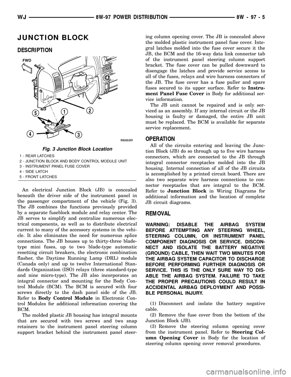
An electrical Junction Block (JB) is concealed
beneath the driver side of the instrument panel in
the passenger compartment of the vehicle (Fig. 3).
The JB combines the functions previously provided
by a separate fuseblock module and relay center. The
JB serves to simplify and centralize numerous elec-
trical components, as well as to distribute electrical
current to many of the accessory systems in the vehi-
cle. It also eliminates the need for numerous splice
connections. The JB houses up to thirty-three blade-
type mini fuses, up to two blade-type automatic
resetting circuit breakers, the electronic combination
flasher, the Daytime Running Lamp (DRL) module
(Canada only) and up to twelve International Stan-
dards Organization (ISO) relays (three standard-type
and nine micro-type). The JB also incorporates an
integral connector and mounting for the Body Con-
trol Module (BCM). The BCM is secured with four
screws directly to the dash panel side of the JB.
Refer toBody Control Modulein Electronic Con-
trol Modules for additional information covering the
BCM.
The molded plastic JB housing has integral mounts
that are secured with two screws and two snap
retainers to the instrument panel steering column
support bracket behind the instrument panel steer-ing column opening cover. The JB is concealed above
the molded plastic instrument panel fuse cover. Inte-
gral latches molded into the fuse cover secure it the
JB, the BCM and the 16-way data link connector tab
of the instrument panel steering column support
bracket. The fuse cover can be pulled downward to
disengage the latches and provide service access to
all of the fuses, relays and wire harness connectors of
the JB. The fuse cover has a fuse puller and spare
fuses secured to its upper surface. Refer toInstru-
ment Panel Fuse Coverin Body for additional ser-
vice information.
The JB unit cannot be repaired and is only ser-
viced as an assembly. If any internal circuit or the JB
housing is faulty or damaged, the entire JB unit
must be replaced. The BCM is available for separate
service replacement.
OPERATION
All of the circuits entering and leaving the Junc-
tion Block (JB) do so through up to five wire harness
connectors, which are connected to the JB through
integral connector receptacles molded into the JB
housing. Internal connection of all of the JB circuits
is accomplished by a printed circuit board. There are
also two separate wire harness connections to con-
nector receptacles that are integral to the BCM.
Refer toJunction Blockin Wiring Diagrams for
additional information and the location of complete
JB circuit diagrams.
REMOVAL
WARNING: DISABLE THE AIRBAG SYSTEM
BEFORE ATTEMPTING ANY STEERING WHEEL,
STEERING COLUMN, OR INSTRUMENT PANEL
COMPONENT DIAGNOSIS OR SERVICE. DISCON-
NECT AND ISOLATE THE BATTERY NEGATIVE
(GROUND) CABLE, THEN WAIT TWO MINUTES FOR
THE AIRBAG SYSTEM CAPACITOR TO DISCHARGE
BEFORE PERFORMING FURTHER DIAGNOSIS OR
SERVICE. THIS IS THE ONLY SURE WAY TO DIS-
ABLE THE AIRBAG SYSTEM. FAILURE TO TAKE
THE PROPER PRECAUTIONS COULD RESULT IN
ACCIDENTAL AIRBAG DEPLOYMENT AND POSSI-
BLE PERSONAL INJURY.
(1) Disconnect and isolate the battery negative
cable.
(2) Remove the fuse cover from the bottom of the
Junction Block (JB).
(3) Remove the steering column opening cover
from the instrument panel. Refer toSteering Col-
umn Opening Coverin Body for the location of
steering column opening cover removal procedures.
Fig. 3 Junction Block Location
1 - REAR LATCHES
2 - JUNCTION BLOCK AND BODY CONTROL MODULE UNIT
3 - INSTRUMENT PANEL FUSE COVER
4 - SIDE LATCH
5 - FRONT LATCHES
WJ8W-97 POWER DISTRIBUTION 8W - 97 - 5
Page 1261 of 2199
DESCRIPTION N´m Ft. In.
Lbs. Lbs.
Transmission Support Bracket
ÐBolt (Manual) 46 34 Ð
Transmission Support Bracket/
CushionÐBolt (4WD Auto) 75 55 Ð
Transmission Support Adaptor
BracketÐBolts (2WD Auto) 75 55 Ð
Exhaust Manifold/PipeÐNuts 27 20 Ð
Intake/Exhaust Manifold
Fasteners #1-5 33 24 Ð
Fasteners #6 and 7 14 Ð 126
Fasteners #8-11 33 24 Ð
Flywheel to Converter
HousingÐBolts38 28 Ð
Flywheel to CrankshaftÐBolts 143 105 Ð
Front Cover to BlockÐBolts
1/4-20 7 Ð 60
5/16-18 22 Ð 192
Fuel RailÐBolts/Stud 12 Ð 108
GeneratorÐBolts 57 42 Ð
Generator Bracket to EngineÐ
Bolts47 35 Ð
Idler Pulley to Cylinder
HeadÐBolt47 35 Ð
Main Bearing CapÐBolts 108 80 Ð
Oil Filter 18 Ð 156
Oil Filter Connector to
Adaptor 47 35 Ð
Block 68 50 Ð
Adaptor Bolts 102 50 Ð
Oil GalleyÐPlug 41 30 Ð
Oil PanÐBolts
1/4-20 9.5 Ð 84
5/16-18 15 Ð 132
Oil PanÐDrain Plug 34 25 Ð
Oil Pump
Mounting Bolts 23 Ð 204
Cover Bolts 8 Ð 70
Rocker Arm Assembly to
Cylinder
HeadÐCapscrews 30 21 Ð
Spark Plugs 37 27 ÐDESCRIPTION N´m Ft. In.
Lbs. Lbs.
Starter MotorÐMounting Bolts 45 33 Ð
Thermostat HousingÐBolts 18 Ð 156
Throttle BodyÐBolts 10 Ð 90
Vibration DamperÐBolt 108 80 Ð
Water Pump to BlockÐBolts 23 17 Ð
AIR CLEANER ELEMENT
REMOVAL - 4.0L
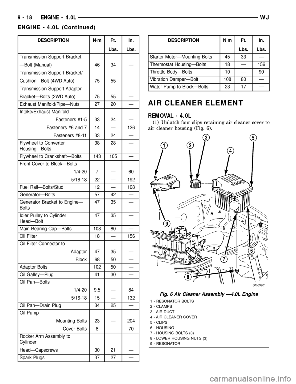
(1) Unlatch four clips retaining air cleaner cover to
air cleaner housing (Fig. 6).
Fig. 6 Air Cleaner Assembly Ð4.0L Engine
1 - RESONATOR BOLTS
2 - CLAMPS
3 - AIR DUCT
4 - AIR CLEANER COVER
5 - CLIPS
6 - HOUSING
7 - HOUSING BOLTS (3)
8 - LOWER HOUSING NUTS (3)
9 - RESONATOR
9 - 18 ENGINE - 4.0LWJ
ENGINE - 4.0L (Continued)
Page 1342 of 2199
(19) Remove the retaining bolt and the camshaft
drive gear.
CAUTION: Do not allow the engine to rotate. severe
damage to the valve train can occur.
CAUTION: Do not overlook the four smaller bolts at
the front of the cylinder head. Do not attempt to
remove the cylinder head without removing these
four bolts.
CAUTION: Do not hold or pry on the camshaft tar-
get wheel for any reason. A damaged target wheel
can result in a vehicle no start condition.
NOTE: The cylinder head is attached to the cylinder
block with fourteen bolts.
(20) Remove the cylinder head retaining bolts.
(21) Remove the cylinder head and gasket. Discard
the gasket.
CAUTION: Do not lay the cylinder head on its gas-
ket sealing surface, do to the design of the cylinder
head gasket any distortion to the cylinder head
sealing surface may prevent the gasket from prop-
erly sealing resulting in leaks.
CLEANING
To ensure engine gasket sealing, proper surface
preparation must be performed, especially with the
use of aluminum engine components. (Refer to 9 -
ENGINE - STANDARD PROCEDURE)
INSPECTION
(1) Inspect the cylinder head for out-of-flatness,
using a straightedge and a feeler gauge. If tolerances
exceed 0.0508 mm (0.002 in.) replace the cylinder
head.
(2) Inspect the valve seats for damage. Service the
valve seats as necessary.
(3) Inspect the valve guides for wear, cracks or
looseness. If either condition exist, replace the cylin-
der head.
INSTALLATION
NOTE: The cylinder head bolts are tightened using
a torque plus angle procedure. The bolts must be
examined BEFORE reuse. If the threads are necked
down the bolts should be replaced.
Necking can be checked by holding a straight edge
against the threads. If all the threads do not contact
the scale, the bolt should be replaced (Fig. 13).
CAUTION: When cleaning cylinder head and cylin-
der block surfaces, DO NOT use a metal scraper
because the surfaces could be cut or ground. Use
only a wooden or plastic scraper.
(1) Clean the cylinder head and cylinder block
mating surfaces (Refer to 9 - ENGINE - STANDARD
PROCEDURE).
(2) Position the new cylinder head gasket on the
locating dowels.
CAUTION: When installing cylinder head, use care
not damage the tensioner arm or the guide arm.
(3) Position the cylinder head onto the cylinder
block. Make sure the cylinder head seats fully over
the locating dowels.
NOTE: The four smaller cylinder head mounting
bolts require sealant to be added to them before
installing. Failure to do so may cause leaks.
(4) Lubricate the cylinder head bolt threads with
clean engine oil and install the ten M10 bolts.
(5) Coat the four M8 cylinder head bolts with
Mopar Lock and Seal Adhesivethen install the
bolts.
NOTE: The cylinder head bolts are tightened using
an angle torque procedure, however, the bolts are
not a torque-to-yield design.
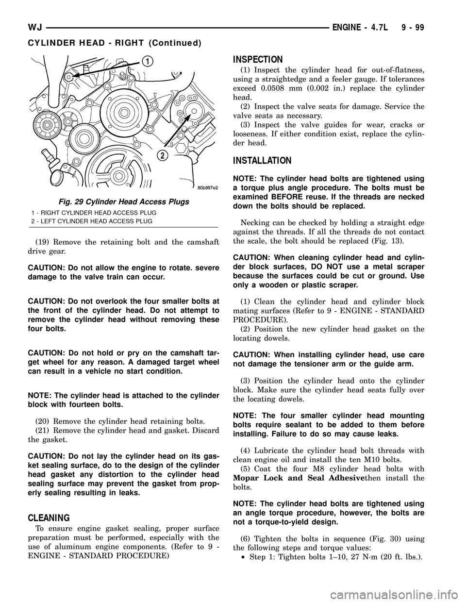
(6) Tighten the bolts in sequence (Fig. 30) using
the following steps and torque values:
²Step 1: Tighten bolts 1±10, 27 N´m (20 ft. lbs.).
Fig. 29 Cylinder Head Access Plugs
1 - RIGHT CYLINDER HEAD ACCESS PLUG
2 - LEFT CYLINDER HEAD ACCESS PLUG
WJENGINE - 4.7L 9 - 99
CYLINDER HEAD - RIGHT (Continued)
Page 1343 of 2199

²Step 2: Verify that bolts 1±10, all reached 27
N´m (20 ft. lbs.), by repeating step-1 without loosen-
ing the bolts. Tighten bolts 11 thru 14 to 14 N´m (10
ft. lbs.).
²Step 3: Tighten bolts 1±10, 90 degrees.
²Step 4: Tighten bolts 1±10, 90 degrees, again.
Tighten bolts 11±14, 26 N´m (19 ft. lbs.)
(7) Install the secondary chain and secondary
chain guide (Refer to 9 - ENGINE/VALVE TIMING/
TIMING BELT/CHAIN AND SPROCKETS -
INSTALLATION).
(8) Install the cylinder head access plug.
(9) Re-set and install the right side secondary
chain tensioner (Refer to 9 - ENGINE/VALVE TIM-
ING/TIMING BELT/CHAIN AND SPROCKETS -
INSTALLATION).
(10) Remove Special Tool 8515.
(11) Install the timing chain cover (Refer to 9 -
ENGINE/VALVE TIMING/TIMING BELT / CHAIN
COVER(S) - INSTALLATION).
(12) Install the crankshaft damper (Refer to 9 -
ENGINE/ENGINE BLOCK/VIBRATION DAMPER -
INSTALLATION).
(13) Install accessory drive belt (Refer to 7 -
COOLING/ACCESSORY DRIVE/DRIVE BELTS -
INSTALLATION).
(14) Install the cylinder head cover (Refer to 9 -
ENGINE/CYLINDER HEAD/CYLINDER HEAD
COVER(S) - INSTALLATION).
(15) Install the intake manifold (Refer to 9 -
ENGINE/MANIFOLDS/INTAKE MANIFOLD -
INSTALLATION).
(16) Install oil fill housing onto cylinder head.
(17) Refill the cooling system (Refer to 7 - COOL-
ING - STANDARD PROCEDURE).
(18) Raise the vehicle.
(19) Install the exhaust pipe onto the right
exhaust manifold.
(20) Lower the vehicle.
(21) Reconnect battery negitive cable.
(22) Start the engine and check for leaks.CAMSHAFT(S) - RIGHT
DESCRIPTION
The camshafts consist of powdered metal steel
lobes which are sinter-bonded to a steel tube. A steel
post or nose piece is friction-welded to the steel cam-
shaft tube. Five bearing journals are machined into
the camshaft, four on the steel tube and one on the
steel nose piece. Camshaft end play is controlled by
two thrust walls that border the nose piece journal.
Engine oil enters the hollow camshafts at the third
journal and lubricates every intake lobe rocker
through a drilled passage in the intake lobe.
REMOVAL
CAUTION: When the timing chain is removed and
the cylinder heads are still installed, DO NOT force-
fully rotate the camshafts or crankshaft indepen-
dently of each other. Severe valve and/or piston
damage can occur.
CAUTION: When removing the cam sprocket, timing
chains or camshaft, Failure to use special tool 8350
will result in hydraulic tensioner ratchet over exten-
sion, Requiring timing chain cover removal to re-set
the tensioner ratchet.
(1) Remove the cylinder head covers (Refer to 9 -
ENGINE/CYLINDER HEAD/CYLINDER HEAD
COVER(S) - REMOVAL).
(2) Set engine to TDC cylinder #1, camshaft
sprocket V8 marks at the 12 o'clock position.
(3) Mark one link on the secondary timing chain
on both sides of the V8 mark on the camshaft
sprocket to aid in installation.
CAUTION: Do not hold or pry on the camshaft tar-
get wheel for any reason, Severe damage will occur
to the target wheel. A damaged target wheel could
cause a vehicle no start condition.
(4) Loosen butDO NOTremove the camshaft
sprocket retaining bolt. Leave bolt snug against
sprocket.
NOTE: The timing chain tensioners must be
secured prior to removing the camshaft sprockets.
Failure to secure tensioners will allow the tension-
ers to extend, requiring timing chain cover removal
in order to reset tensioners.
CAUTION: Do not force wedge past the narrowest
point between the chain strands. Damage to the
tensioners may occur.
Fig. 30 Cylinder Head Tightening Sequence
9 - 100 ENGINE - 4.7LWJ
CYLINDER HEAD - RIGHT (Continued)
Page 1354 of 2199
Bearing
MarkSIZE USED WITH
JOURNAL SIZE
.025 US.025 mm 50.983-50.967 mm
(.001 in.) (2.0073-2.0066 in.)
Std.STANDARD 50.992-51.008 mm
(2.0076-2.0082 in.)
.250 US.250 mm 50.758-50.742 mm
(.010 in.) (1.9984-1.9978 in.)
(9) Repeat the Plastigage measurement to verify
your bearing selection prior to final assembly.
(10) Once you have selected the proper insert,
install the insert and cap. Tighten the connecting rod
bolts to 27 N´m (20 ft. lbs.) plus a 90É turn.
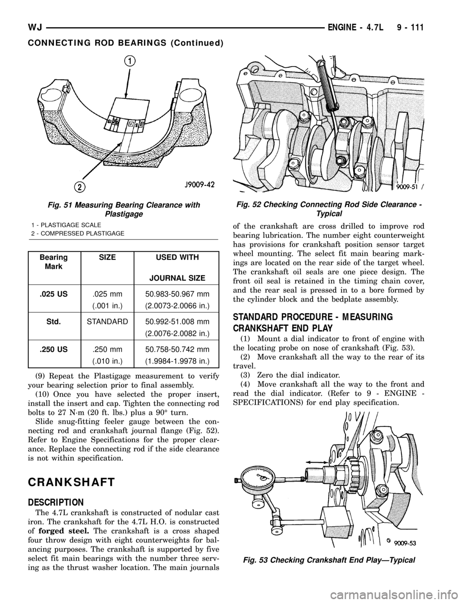
Slide snug-fitting feeler gauge between the con-
necting rod and crankshaft journal flange (Fig. 52).
Refer to Engine Specifications for the proper clear-
ance. Replace the connecting rod if the side clearance
is not within specification.
CRANKSHAFT
DESCRIPTION
The 4.7L crankshaft is constructed of nodular cast
iron. The crankshaft for the 4.7L H.O. is constructed
offorged steel.The crankshaft is a cross shaped
four throw design with eight counterweights for bal-
ancing purposes. The crankshaft is supported by five
select fit main bearings with the number three serv-
ing as the thrust washer location. The main journalsof the crankshaft are cross drilled to improve rod
bearing lubrication. The number eight counterweight
has provisions for crankshaft position sensor target
wheel mounting. The select fit main bearing mark-
ings are located on the rear side of the target wheel.
The crankshaft oil seals are one piece design. The
front oil seal is retained in the timing chain cover,
and the rear seal is pressed in to a bore formed by
the cylinder block and the bedplate assembly.
STANDARD PROCEDURE - MEASURING
CRANKSHAFT END PLAY
(1) Mount a dial indicator to front of engine with
the locating probe on nose of crankshaft (Fig. 53).
(2) Move crankshaft all the way to the rear of its
travel.
(3) Zero the dial indicator.
(4) Move crankshaft all the way to the front and
read the dial indicator. (Refer to 9 - ENGINE -
SPECIFICATIONS) for end play specification.
Fig. 51 Measuring Bearing Clearance with
Plastigage
1 - PLASTIGAGE SCALE
2 - COMPRESSED PLASTIGAGE
Fig. 52 Checking Connecting Rod Side Clearance -
Typical
Fig. 53 Checking Crankshaft End PlayÐTypical
WJENGINE - 4.7L 9 - 111
CONNECTING ROD BEARINGS (Continued)
Page 1460 of 2199
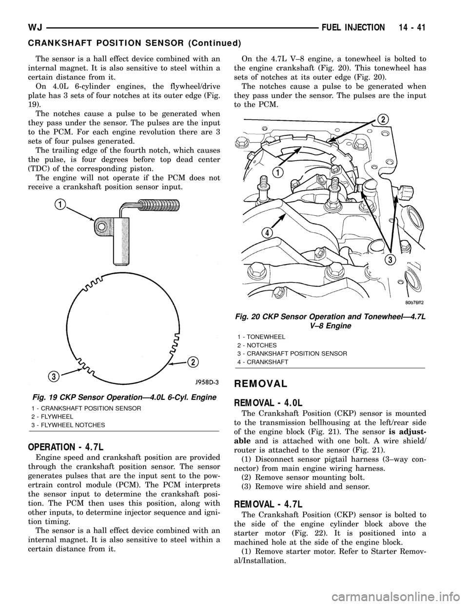
The sensor is a hall effect device combined with an
internal magnet. It is also sensitive to steel within a
certain distance from it.
On 4.0L 6-cylinder engines, the flywheel/drive
plate has 3 sets of four notches at its outer edge (Fig.
19).
The notches cause a pulse to be generated when
they pass under the sensor. The pulses are the input
to the PCM. For each engine revolution there are 3
sets of four pulses generated.
The trailing edge of the fourth notch, which causes
the pulse, is four degrees before top dead center
(TDC) of the corresponding piston.
The engine will not operate if the PCM does not
receive a crankshaft position sensor input.
OPERATION - 4.7L
Engine speed and crankshaft position are provided
through the crankshaft position sensor. The sensor
generates pulses that are the input sent to the pow-
ertrain control module (PCM). The PCM interprets
the sensor input to determine the crankshaft posi-
tion. The PCM then uses this position, along with
other inputs, to determine injector sequence and igni-
tion timing.
The sensor is a hall effect device combined with an
internal magnet. It is also sensitive to steel within a
certain distance from it.On the 4.7L V±8 engine, a tonewheel is bolted to
the engine crankshaft (Fig. 20). This tonewheel has
sets of notches at its outer edge (Fig. 20).
The notches cause a pulse to be generated when
they pass under the sensor. The pulses are the input
to the PCM.
REMOVAL
REMOVAL - 4.0L
The Crankshaft Position (CKP) sensor is mounted
to the transmission bellhousing at the left/rear side
of the engine block (Fig. 21). The sensoris adjust-
ableand is attached with one bolt. A wire shield/
router is attached to the sensor (Fig. 21).
(1) Disconnect sensor pigtail harness (3±way con-
nector) from main engine wiring harness.
(2) Remove sensor mounting bolt.
(3) Remove wire shield and sensor.
REMOVAL - 4.7L
The Crankshaft Position (CKP) sensor is bolted to
the side of the engine cylinder block above the
starter motor (Fig. 22). It is positioned into a
machined hole at the side of the engine block.
(1) Remove starter motor. Refer to Starter Remov-
al/Installation.
Fig. 19 CKP Sensor OperationÐ4.0L 6-Cyl. Engine
1 - CRANKSHAFT POSITION SENSOR
2 - FLYWHEEL
3 - FLYWHEEL NOTCHES
Fig. 20 CKP Sensor Operation and TonewheelÐ4.7L
V±8 Engine
1 - TONEWHEEL
2 - NOTCHES
3 - CRANKSHAFT POSITION SENSOR
4 - CRANKSHAFT
WJFUEL INJECTION 14 - 41
CRANKSHAFT POSITION SENSOR (Continued)