2002 JEEP GRAND CHEROKEE Diffe
[x] Cancel search: DiffePage 14 of 2199
Propylene-glycol/ethylene-glycol Mixtures can
cause the destabilization of various corrosion inhibi-
tors, causing damage to the various cooling system
components. Also, once ethylene-glycol and propy-
lene-glycol based coolants are mixed in the vehicle,
conventional methods of determining freeze point will
not be accurate. Both the refractive index and spe-
cific gravity differ between ethylene glycol and propy-
lene glycol.
DESCRIPTION - ENGINE COOLANT
WARNING: ANTIFREEZE IS AN ETHYLENE GLYCOL
BASE COOLANT AND IS HARMFUL IF SWAL-
LOWED OR INHALED. IF SWALLOWED, DRINK
TWO GLASSES OF WATER AND INDUCE VOMIT-
ING. IF INHALED, MOVE TO FRESH AIR AREA.
SEEK MEDICAL ATTENTION IMMEDIATELY. DO NOT
STORE IN OPEN OR UNMARKED CONTAINERS.
WASH SKIN AND CLOTHING THOROUGHLY AFTER
COMING IN CONTACT WITH ETHYLENE GLYCOL.
KEEP OUT OF REACH OF CHILDREN. DISPOSE OF
GLYCOL BASE COOLANT PROPERLY, CONTACT
YOUR DEALER OR GOVERNMENT AGENCY FOR
LOCATION OF COLLECTION CENTER IN YOUR
AREA. DO NOT OPEN A COOLING SYSTEM WHEN
THE ENGINE IS AT OPERATING TEMPERATURE OR
HOT UNDER PRESSURE, PERSONAL INJURY CAN
RESULT. AVOID RADIATOR COOLING FAN WHEN
ENGINE COMPARTMENT RELATED SERVICE IS
PERFORMED, PERSONAL INJURY CAN RESULT.
CAUTION: Use of Propylene Glycol based coolants
is not recommended, as they provide less freeze
protection and less corrosion protection.
The cooling system is designed around the coolant.
The coolant must accept heat from engine metal, in
the cylinder head area near the exhaust valves and
engine block. Then coolant carries the heat to the
radiator where the tube/fin radiator can transfer the
heat to the air.
The use of aluminum cylinder blocks, cylinder
heads, and water pumps requires special corrosion
protection. MopartAntifreeze/Coolant, 5
Year/100,000 Mile Formula (MS-9769), or the equiva-
lent ethylene glycol base coolant with organic corro-
sion inhibitors (called HOAT, for Hybrid Organic
Additive Technology) is recommended. This coolant
offers the best engine cooling without corrosion when
mixed with 50% Ethylene Glycol and 50% distilled
water to obtain a freeze point of -37ÉC (-35ÉF). If it
loses color or becomes contaminated, drain, flush,
and replace with fresh properly mixed coolant solu-
tion.CAUTION: MoparTAntifreeze/Coolant, 5
Year/100,000 Mile Formula (MS-9769) may not be
mixed with any other type of antifreeze. Mixing of
coolants other than specified (non-HOAT or other
HOAT), may result in engine damage that may not
be covered under the new vehicle warranty, and
decreased corrosion protection.
COOLANT PERFORMANCE
The required ethylene-glycol (antifreeze) and water
mixture depends upon climate and vehicle operating
conditions. The coolant performance of various mix-
tures follows:
Pure Water-Water can absorb more heat than a
mixture of water and ethylene-glycol. This is for pur-
pose of heat transfer only. Water also freezes at a
higher temperature and allows corrosion.
100 percent Ethylene-Glycol-The corrosion
inhibiting additives in ethylene-glycol need the pres-
ence of water to dissolve. Without water, additives
form deposits in system. These act as insulation
causing temperature to rise to as high as 149ÉC
(300ÉF). This temperature is hot enough to melt plas-
tic and soften solder. The increased temperature can
result in engine detonation. In addition, 100 percent
ethylene-glycol freezes at -22ÉC (-8ÉF).
50/50 Ethylene-Glycol and Water-Is the recom-
mended mixture, it provides protection against freez-
ing to -37ÉC (-34ÉF). The antifreeze concentration
must alwaysbe a minimum of 44 percent, year-
round in all climates. If percentage is lower, engine
parts may be eroded by cavitation. Maximum protec-
tion against freezing is provided with a 68 percent
antifreeze concentration, which prevents freezing
down to -67.7ÉC (-90ÉF). A higher percentage will
freeze at a warmer temperature. Also, a higher per-
centage of antifreeze can cause the engine to over-
heat because specific heat of antifreeze is lower than
that of water.
CAUTION: Richer antifreeze mixtures cannot be
measured with normal field equipment and can
cause problems associated with 100 percent ethyl-
ene-glycol.
COOLANT SELECTION AND ADDITIVES
The use of aluminum cylinder blocks, cylinder
heads and water pumps requires special corrosion
protection. Only MopartAntifreeze/Coolant, 5
Year/100,000 Mile Formula (glycol base coolant with
corrosion inhibitors called HOAT, for Hybrid Organic
Additive Technology) is recommended. This coolant
offers the best engine cooling without corrosion when
mixed with 50% distilled water to obtain to obtain a
freeze point of -37ÉC (-35ÉF). If it loses color or
WJLUBRICATION & MAINTENANCE 0 - 3
FLUID TYPES (Continued)
Page 17 of 2199
DESCRIPTION - ENGINE OIL - DIESEL
ENGINES
Use only Diesel Engine Oil meeting standardMIL-
2104Cor API ClassificationCD or higherorCCML
D4, D5.
SAE VISCOSITY GRADE
CAUTION: Low viscosity oils must have the proper
API quality or the CCMC G5 designation.
To assure of properly formulated engine oils, it is
recommended that SAE Grade 10W-40 engine oils
that meet Chrysler material standard MS-6395, be
used. European Grade 10W-40 oils are also accept-
able.
Oils of the SAE 5W-40 or 8W-80 grade number are
preferred when minimum temperatures consistently
fall below -12ÉC.
OPERATION - AUTOMATIC TRANSMISSION
FLUID
The automatic transmission fluid is selected based
upon several qualities. The fluid must provide a high
level of protection for the internal components by
providing a lubricating film between adjacent metal
components. The fluid must also be thermally stable
so that it can maintain a consistent viscosity through
a large temperature range. If the viscosity stays con-
stant through the temperature range of operation,
transmission operation and shift feel will remain con-
sistent. Transmission fluid must also be a good con-
ductor of heat. The fluid must absorb heat from the
internal transmission components and transfer that
heat to the transmission case.
FLUID FILL/CHECK
LOCATIONS
INSPECTION - FLUID FILL/CHECK LOCATIONS
The fluid fill/check locations and lubrication points
are located in each applicable group.
MAINTENANCE SCHEDULES
DESCRIPTION
9Maintenance Schedule Information not included in
this section, is located in the appropriate Owner's
Manual.9
LIFT POINTS
STANDARD PROCEDURE - HOISTING AND
JACKING RECOMMENDATIONS
FLOOR JACK
When properly positioned, a floor jack can be used
to lift a WJ vehicle (Fig. 7). Support the vehicle in
the raised position with jack stands at the front and
rear ends of the frame rails.
CAUTION: Do not attempt to lift a vehicle with a
floor jack positioned under:
²An axle tube.
²Aluminum differential.
²A body side sill.
²A steering linkage component.
²A drive shaft.
²The engine or transmission oil pan.
²The fuel tank.
²A front suspension arm.
HOIST
A vehicle can be lifted with:
²A single-post, frame-contact hoist.
²A twin-post, chassis hoist.
²A ramp-type, drive-on hoist.
NOTE: When a frame-contact type hoist is used,
verify that the lifting pads are positioned properly
(Fig. 7).
WARNING: THE HOISTING AND JACK LIFTING
POINTS PROVIDED ARE FOR A COMPLETE VEHI-
CLE. WHEN A CHASSIS OR DRIVETRAIN COMPO-
NENT IS REMOVED FROM A VEHICLE, THE
CENTER OF GRAVITY IS ALTERED MAKING SOME
HOISTING CONDITIONS UNSTABLE. PROPERLY
SUPPORT OR SECURE VEHICLE TO HOISTING
DEVICE WHEN THESE CONDITIONS EXIST.
0 - 6 LUBRICATION & MAINTENANCEWJ
FLUID TYPES (Continued)
Page 24 of 2199
WHEEL ALIGNMENT
TABLE OF CONTENTS
page page
WHEEL ALIGNMENT
DESCRIPTION..........................3
OPERATION............................3
STANDARD PROCEDURE
STANDARD PROCEDURE - CAMBER.......3STANDARD PROCEDURE - CASTER.......4
STANDARD PROCEDURE - TOE POSITION . . 4
SPECIFICATIONS
ALIGNMENT..........................5
WHEEL ALIGNMENT
DESCRIPTION
Wheel alignment involves the correct positioning of
the wheels in relation to the vehicle. The positioning
is accomplished through suspension and steering
linkage adjustments. An alignment is considered
essential for efficient steering, good directional stabil-
ity and to minimize tire wear. The most important
measurements of an alignment are caster, camber
and toe position (Fig. 1).
CAUTION: Never attempt to modify suspension or
steering components by heating or bending.
CAUTION: Components attached with a nut and cot-
ter pin must be torqued to specification. Then if the
slot in the nut does not line up with the cotter pin
hole, tighten nut until it is aligned. Never loosen the
nut to align the cotter pin hole.
NOTE: Periodic lubrication of the front suspension/
steering system components may be required. Rub-
ber bushings must never be lubricated, Refer to
Lubrication And Maintenance for the recommended
maintenance schedule.
OPERATION
²CASTERis the forward or rearward tilt of the
steering knuckle from vertical. Tilting the top of the
knuckle rearward provides positive caster. Tilting the
top of the knuckle forward provides negative caster.
Caster is a directional stability angle. This angle
enables the front wheels to return to a straight
ahead position after turns (Fig. 1).
²CAMBERis the inward or outward tilt of the
wheel relative to the center of the vehicle. Tilting the
top of the wheel inward provides negative camber.
Tilting the top of the wheel outward provides positive
camber. Incorrect camber will cause wear on theinside or outside edge of the tire. The angle is not
adjustable, damaged component(s) must be replaced
to correct the camber angle (Fig. 1).
²WHEEL TOE POSITIONis the difference
between the leading inside edges and trailing inside
edges of the front tires. Incorrect wheel toe position
is the most common cause of unstable steering and
uneven tire wear. The wheel toe position is thefinal
front wheel alignment adjustment (Fig. 1).
²STEERING AXIS INCLINATION ANGLEis
measured in degrees and is the angle that the steer-
ing knuckles are tilted. The inclination angle has a
fixed relationship with the camber angle. It will not
change except when a spindle or ball stud is dam-
aged or bent. The angle is not adjustable, damaged
component(s) must be replaced to correct the steering
axis inclination angle.
²THRUST ANGLEis the angle of the rear axle
relative to the centerline of the vehicle. Incorrect
thrust angle can cause off-center steering and exces-
sive tire wear. This angle is not adjustable, damaged
component(s) must be replaced to correct the thrust
angle (Fig. 1).
STANDARD PROCEDURE
STANDARD PROCEDURE - CAMBER
Before each alignment reading the vehicle should
be jounced (rear first, then front). Grasp each
bumper at the center and jounce the vehicle up and
down three times. Always release the bumper in the
down position.
To obtain an accurate alignment, a 4 wheel align-
ment machine must be used and the equipment cali-
bration verified.
The wheel camber angle is preset. This angle is not
adjustable and cannot be altered.
WJWHEEL ALIGNMENT 2 - 3
Page 26 of 2199

NOTE: Make sure the toe setting does not change
during clamp tightening.
(6) Verify alignment specifications, then turn the
engine off.
STEERING WHEEL CENTERING
NOTE: The steering wheel can be centered without
affecting the toe position.
(1) Loosen the drag link adjustment sleeve clamp
bolts.
(2) Turn the adjustment sleeve to center the
wheel.
(3) Position the clamp bolts as shown (Fig. 2)for
proper clearance.
(4) Tighten the clamp bolts to 68 N´m (50 ft. lbs.).
(5) Road test the vehicle to verify the wheel is cen-
tered.
SPECIFICATIONS
ALIGNMENT
NOTE: Specifications are in degrees.
FRONT WHEELS - STANDARD SUSPENSION
SPECIFICATIONS
DESCRIPTION SPECIFICATION
PREFERRED CASTER
+ 6.75ÉCAMBER
20.37ÉTOTAL
TOE-IN
+ 0.20É
RANGE + 6.0É to
+ 7.5É20.75É
to + 0.5É+ .14É to
+ .26É
MAX RT/LT
DIFFERENCE0.5É 0.5É 0.5É
FRONT WHEELS - UP-COUNTRY SUSPENSION
SPECIFICATIONS
DESCRIPTION SPECIFICATION
PREFERRED CASTER
+ 6.5ÉCAMBER
20.37ÉTOTAL
TOE-IN
+ 0.20É
RANGE + 5.7É to
+ 7.2É20.75É
to+0É+ 0.0É to
+ .36É
MAX RT/LT
DIFFERENCE0.5É 0.5É 0.06É
REAR AXLE
SPECIFICATIONS
DESCRIPTION SPECIFICATION
PREFERRED CAMBER
±.37ÉTHRUST
ANGLE
0ÉTOTAL
TOE-IN
+.37É
RANGE 0É to
±.75É 0.25É 0É to
+.70É
Fig. 2 Steering Linkage
1 - DRAG LINK ADJUSTMENT SLEEVE
2 - TIE ROD ADJUSTMENT SLEEVE
WJWHEEL ALIGNMENT 2 - 5
WHEEL ALIGNMENT (Continued)
Page 42 of 2199

STABILIZER BAR
DESCRIPTION
The stabilizer bar extends across the back side of
the rear axle. Links are connected between the bar
and frame rail brackets. The stabilizer bar and links
are isolated by rubber bushings.
OPERATION
The stabilizer bar is used to control vehicle body
roll, during turns. The bar helps control the vehicle
body in relationship to the suspension.
REMOVAL
(1) Raise and support the vehicle.
(2) Remove the stabilizer bar links from stabilizer
bar and frame mount. (Fig. 7).
(3) Remove the stabilizer bar retainer bolts.
(4) Remove the stabilizer bar.
INSTALLATION
(1) Position the stabilizer bar on the axle and
install the retainers and bolts. Ensure the bar is cen-
tered with equal spacing on both sides. Tighten the
bolts to 54 N´m (40 ft. lbs.).
(2) Install the links to the stabilizer bar and frame
brackets.
(3) Tighten the nuts at the stabilizer bar to 54
N´m (40 ft. lbs.).
(4) Tighten the nuts at the frame brackets to 92
N´m (68 ft. lbs.).
(5) Remove support and lower the vehicle.
UPPER BALL JOINT
DESCRIPTION - UPPER SUSPENSION ARM,
BUSHINGS, AND BALL JOINT
The suspension arm uses vertical spool bushings to
isolate road noise. The suspension arm is bolted
through bushings to cage nuts in the body and a ball
joint plate to the top of the differential housing.
OPERATION - UPPER SUSPENSION ARM,
BUSHINGS, AND BALL JOINT
The upper suspension arm provides fore/aft and
lateral location of the rear axle. The suspension arm
travel is limited through the use of jounce bumpers
in compression and shock absorbers in rebound.
REMOVAL
(1) Raise and support the vehicle.
(2) Support the rear axle with a hydraulic jack.
(3) Remove the ball joint nut from the top of the
upper suspension arm (Fig. 8).
(4) Separate ball joint from the arm with Remover
8278 (Fig. 9).
NOTE: It may be necessary to strike the upper con-
trol arm with a hammer to separate the ball joint
from the arm.
(5) Remove the ball joint mounting bolts (Fig.
10)from the differential housing.
(6) Remove the ball joint from the differential
housing.
Fig. 6 Isolator Spring Locator - Typical
1 - LOWER ISOLATOR
2 - SPRING LOCATOR
3 - COIL SPRING
Fig. 7 Rear Stabilizer Bar
1 - LINK
2 - RETAINER
3 - BUSHING
4 - STABILIZER BAR
WJREAR 2 - 21
SPRING (Continued)
Page 43 of 2199
INSTALLATION
(1) Install the ball joint on the differential hous-
ing.
(2) Install the ball joint mounting bolts and
tighten to 136 N´m (100 ft. lbs.).
(3) Raise the rear axle with a hydraulic jack to
align the upper arm with the ball joint.(4) Pull the arm down on the ball joint stud and
install anewnut. Tighten the nut to 142 N´m (105
ft. lbs.).
(5) Remove the supports and lower the vehicle.
UPPER CONTROL ARM
DESCRIPTION
The suspension arm uses vertical spool bushings to
isolate road noise. The suspension arm is bolted
through bushings to cage nuts in the body and a ball
joint plate to the top of the differential housing.
OPERATION
The upper suspension arm provides fore/aft and
lateral location of the rear axle. The suspension arm
travel is limited through the use of jounce bumpers
in compression and shock absorbers in rebound.
REMOVAL
(1) Raise and support the vehicle.
(2) Support the rear axle with a hydraulic jack.
(3) Remove the park brake cables and brake hose
from the arm (Fig. 11).
(4) Remove the ball joint nut from the top of the
upper suspension arm (Fig. 12).
(5) Separate ball joint from the arm with Remover
8278 (Fig. 13).
Fig. 8 Ball Joint Nut
1 - BALL JOINT NUT
2 - UPPER SUSPENSION ARM
Fig. 9 Separate Ball Joint
1 - REMOVER
2 - UPPER SUSPENSION ARM
3 - BALL JOINT STUD
Fig. 10 Ball Joint Mounting Bolts
1 - BALL JOINT
2 - MOUNTING BOLTS
2 - 22 REARWJ
UPPER BALL JOINT (Continued)
Page 46 of 2199

DIFFERENTIAL & DRIVELINE
TABLE OF CONTENTS
page page
PROPELLER SHAFT......................1
FRONT TUBE AXLE......................14
FRONT AXLE - 186FBI....................15REAR AXLE - 198RBI.....................50
REAR AXLE - 226RBA....................90
PROPELLER SHAFT
TABLE OF CONTENTS
page page
PROPELLER SHAFT
DIAGNOSIS AND TESTING................1
STANDARD PROCEDURES................3
SPECIFICATIONS........................5
SPECIAL TOOLS........................5
PROPELLER SHAFT - FRONT
REMOVAL.............................6
INSTALLATION..........................6
PROPELLER SHAFT - FRONT 4.7L
REMOVAL.............................6INSTALLATION..........................7
PROPELLER SHAFT - REAR
REMOVAL.............................7
INSTALLATION..........................7
SINGLE CARDAN UNIVERSAL JOINTS
DISASSEMBLY..........................8
ASSEMBLY.............................9
DOUBLE CARDAN UNIVERSAL JOINTS
DISASSEMBLY..........................9
ASSEMBLY............................10
PROPELLER SHAFT
DIAGNOSIS AND TESTING
VIBRATION
Tires that are out-of-round, or wheels that are
unbalanced, will cause a low frequency vibration.
(Refer to 22 - TIRES/WHEELS - DIAGNOSIS AND
TESTING)
Brake rotors that are unbalanced will cause a
harsh, low frequency vibration. (Refer to 5 - BRAKES
- DIAGNOSIS AND TESTING)Driveline vibration can also result from loose or
damaged engine mounts.
Propeller shaft vibration increases as the vehicle
speed is increased. A vibration that occurs within a
specific speed range is not usually caused by a pro-
peller shaft being unbalanced. Defective universal
joints, or an incorrect propeller shaft angle, are usu-
ally the cause of such a vibration.
WJDIFFERENTIAL & DRIVELINE 3 - 1
Page 48 of 2199
(10) Start the engine and re-check for vibration. If
there is little or no change in vibration, move the
clamp to one of the other three positions. Repeat the
vibration test.
(11) If there is no difference in vibration at the
other positions, the source of the vibration may not
be propeller shaft.
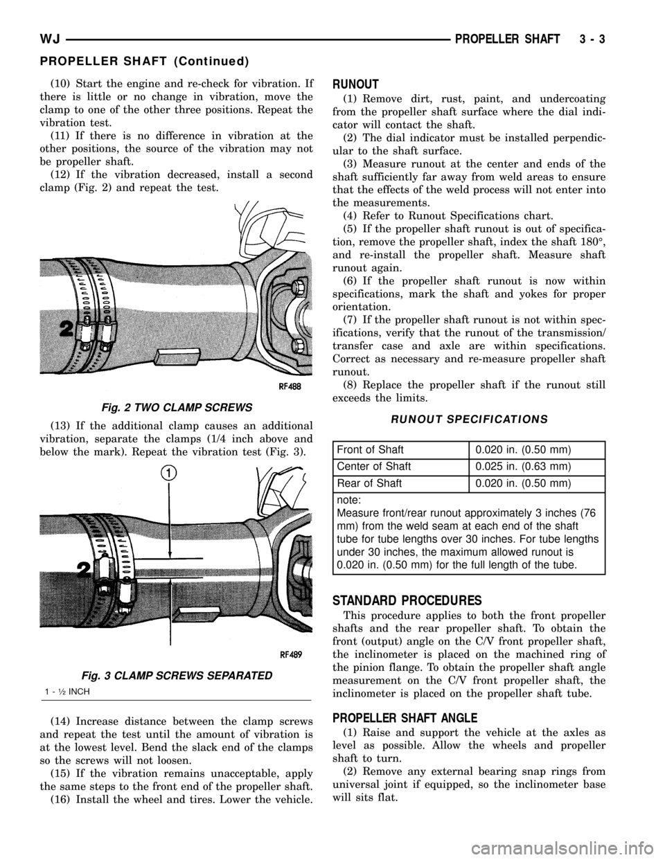
(12) If the vibration decreased, install a second
clamp (Fig. 2) and repeat the test.
(13) If the additional clamp causes an additional
vibration, separate the clamps (1/4 inch above and
below the mark). Repeat the vibration test (Fig. 3).
(14) Increase distance between the clamp screws
and repeat the test until the amount of vibration is
at the lowest level. Bend the slack end of the clamps
so the screws will not loosen.
(15) If the vibration remains unacceptable, apply
the same steps to the front end of the propeller shaft.
(16) Install the wheel and tires. Lower the vehicle.RUNOUT
(1) Remove dirt, rust, paint, and undercoating
from the propeller shaft surface where the dial indi-
cator will contact the shaft.
(2) The dial indicator must be installed perpendic-
ular to the shaft surface.
(3) Measure runout at the center and ends of the
shaft sufficiently far away from weld areas to ensure
that the effects of the weld process will not enter into
the measurements.
(4) Refer to Runout Specifications chart.
(5) If the propeller shaft runout is out of specifica-
tion, remove the propeller shaft, index the shaft 180É,
and re-install the propeller shaft. Measure shaft
runout again.
(6) If the propeller shaft runout is now within
specifications, mark the shaft and yokes for proper
orientation.
(7) If the propeller shaft runout is not within spec-
ifications, verify that the runout of the transmission/
transfer case and axle are within specifications.
Correct as necessary and re-measure propeller shaft
runout.
(8) Replace the propeller shaft if the runout still
exceeds the limits.
RUNOUT SPECIFICATIONS
Front of Shaft 0.020 in. (0.50 mm)
Center of Shaft 0.025 in. (0.63 mm)
Rear of Shaft 0.020 in. (0.50 mm)
note:
Measure front/rear runout approximately 3 inches (76
mm) from the weld seam at each end of the shaft
tube for tube lengths over 30 inches. For tube lengths
under 30 inches, the maximum allowed runout is
0.020 in. (0.50 mm) for the full length of the tube.
STANDARD PROCEDURES
This procedure applies to both the front propeller
shafts and the rear propeller shaft. To obtain the
front (output) angle on the C/V front propeller shaft,
the inclinometer is placed on the machined ring of
the pinion flange. To obtain the propeller shaft angle
measurement on the C/V front propeller shaft, the
inclinometer is placed on the propeller shaft tube.
PROPELLER SHAFT ANGLE
(1) Raise and support the vehicle at the axles as
level as possible. Allow the wheels and propeller
shaft to turn.
(2) Remove any external bearing snap rings from
universal joint if equipped, so the inclinometer base
will sits flat.
Fig. 2 TWO CLAMP SCREWS
Fig. 3 CLAMP SCREWS SEPARATED
1 - ó INCH
WJPROPELLER SHAFT 3 - 3
PROPELLER SHAFT (Continued)