2002 JEEP GRAND CHEROKEE Oil pan removal
[x] Cancel search: Oil pan removalPage 1285 of 2199
CRANKSHAFT OIL SEAL -
REAR
REMOVAL
The crankshaft rear main bearing oil seal consists
of two half pieces of viton with a single lip that effec-
tively seals the rear of the crankshaft. Replace the
upper and lower seal halves as a unit to ensure leak-
free operation.
(1) Remove transmission inspection cover.
(2) Remove oil pan. (Refer to 9 - ENGINE/LUBRI-
CATION/OIL PAN - REMOVAL)
(3) Remove main bearing cap brace.
(4) Remove rear main bearing cap (No.7).
(5) Push upper seal out of the groove. Ensure that
the crankshaft and seal groove are not damaged.
(6) Remove lower half of the seal from the bearing
cap.
INSTALLATION
The crankshaft rear main bearing oil seal consists
of two half pieces of viton with a single lip that effec-
tively seals the rear of the crankshaft. Replace the
upper and lower seal halves as a unit to ensure leak-
free operation.
(1) Wipe the seal surface area of the crankshaft
until it is clean.
(2) Apply a thin coat of engine oil.
(3) Coat lip of the seal with engine oil.
(4) Carefully position the upper seal into the
groove in the cylinder block. The lip of the seal faces
toward the front of the engine.
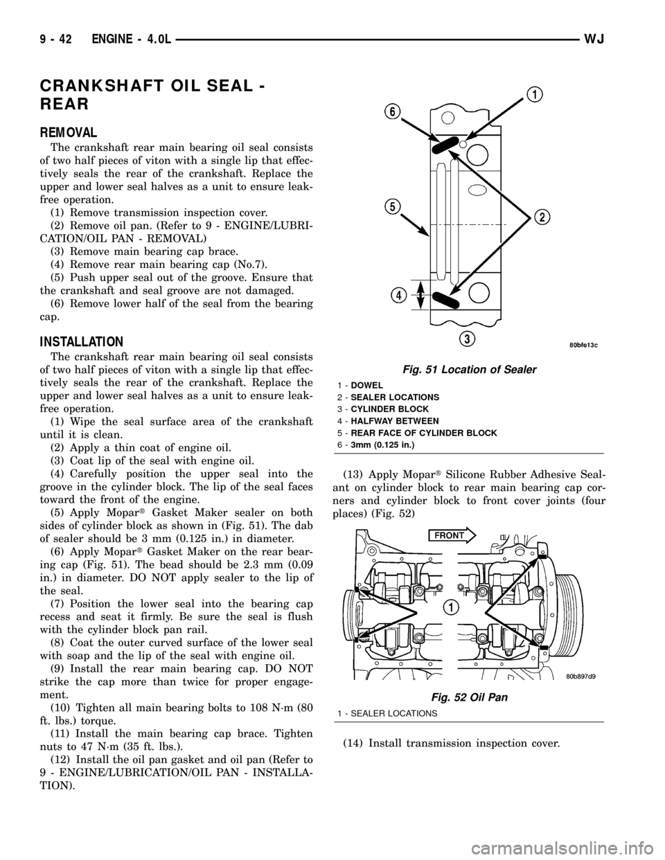
(5) Apply MopartGasket Maker sealer on both
sides of cylinder block as shown in (Fig. 51). The dab
of sealer should be 3 mm (0.125 in.) in diameter.
(6) Apply MopartGasket Maker on the rear bear-
ing cap (Fig. 51). The bead should be 2.3 mm (0.09
in.) in diameter. DO NOT apply sealer to the lip of
the seal.
(7) Position the lower seal into the bearing cap
recess and seat it firmly. Be sure the seal is flush
with the cylinder block pan rail.
(8) Coat the outer curved surface of the lower seal
with soap and the lip of the seal with engine oil.
(9) Install the rear main bearing cap. DO NOT
strike the cap more than twice for proper engage-
ment.
(10) Tighten all main bearing bolts to 108 N´m (80
ft. lbs.) torque.
(11) Install the main bearing cap brace. Tighten
nuts to 47 N´m (35 ft. lbs.).
(12) Install the oil pan gasket and oil pan (Refer to
9 - ENGINE/LUBRICATION/OIL PAN - INSTALLA-
TION).(13) Apply MopartSilicone Rubber Adhesive Seal-
ant on cylinder block to rear main bearing cap cor-
ners and cylinder block to front cover joints (four
places) (Fig. 52)
(14) Install transmission inspection cover.
Fig. 51 Location of Sealer
1-DOWEL
2-SEALER LOCATIONS
3-CYLINDER BLOCK
4-HALFWAY BETWEEN
5-REAR FACE OF CYLINDER BLOCK
6-3mm (0.125 in.)
Fig. 52 Oil Pan
1 - SEALER LOCATIONS
9 - 42 ENGINE - 4.0LWJ
Page 1288 of 2199
PISTON SIZE CHART
CYLINDER BORE SIZE PISTON LETTER SIZE
98.438 - 98.448 mm
(3.8755 - 3.8759 in.)A
98.448 - 98.458 mm
(3.8759 - 3.8763 in.)B
98.458 - 98.468 mm
(3.8763 - 3.8767 in.)C
98.468 - 98.478 mm
(3.8767 - 3.8771 in.)D
98.478 - 98.488 mm
(3.8771 - 3.8775 in.)E
98.488 - 98.498 mm
(3.8775 - 3.8779 in.)F
REMOVAL
(1) Remove the engine cylinder head cover. (Refer
to 9 - ENGINE/CYLINDER HEAD/CYLINDER
HEAD COVER(S) - REMOVAL).
(2) Remove the rocker arms, bridges and pivots.
(3) Remove the push rods.
(4) Remove the engine cylinder head. (Refer to 9 -
ENGINE/CYLINDER HEAD - REMOVAL).
(5) Position the pistons one at a time near the bot-
tom of the stroke. Use a ridge reamer to remove theridge from the top end of the cylinder walls. Use a
protective cloth to collect the cuttings.
(6) Raise the vehicle.
(7) Drain the engine oil.
(8) Remove the oil pan and gasket. (Refer to 9 -
ENGINE/LUBRICATION/OIL PAN - REMOVAL).
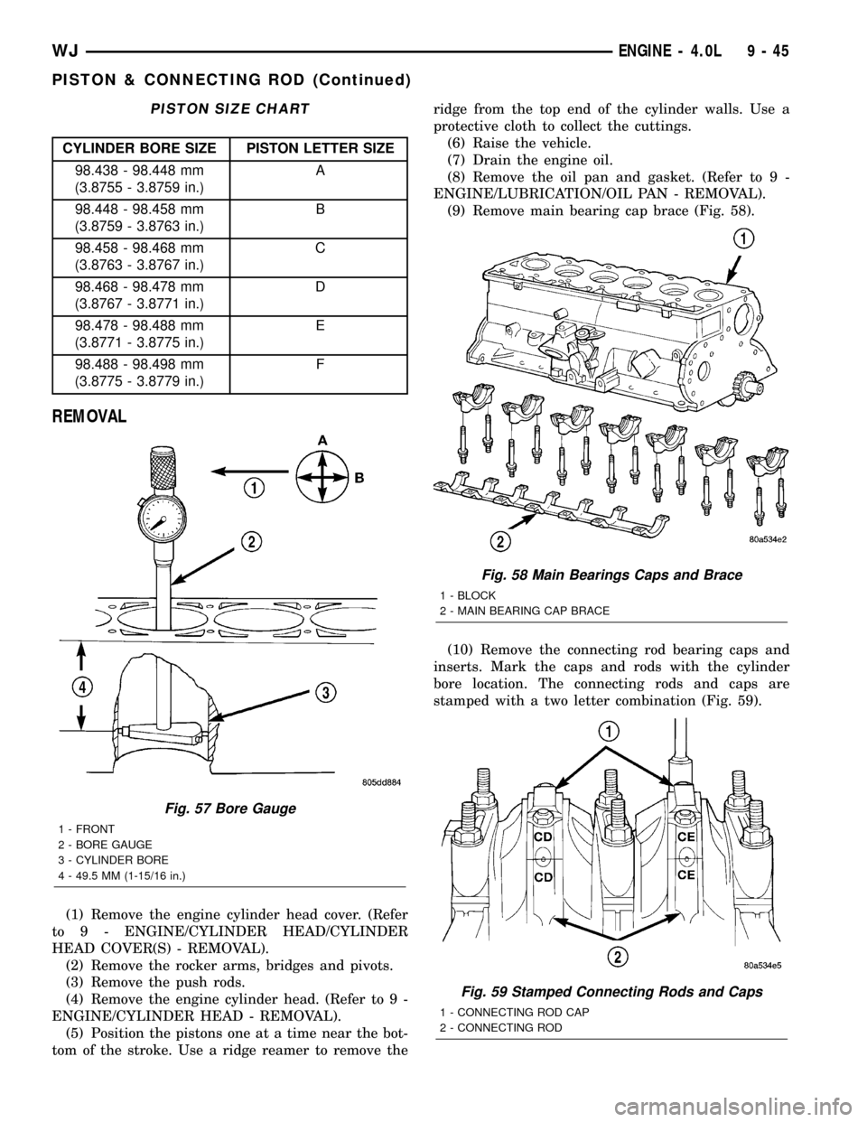
(9) Remove main bearing cap brace (Fig. 58).
(10) Remove the connecting rod bearing caps and
inserts. Mark the caps and rods with the cylinder
bore location. The connecting rods and caps are
stamped with a two letter combination (Fig. 59).
Fig. 57 Bore Gauge
1 - FRONT
2 - BORE GAUGE
3 - CYLINDER BORE
4 - 49.5 MM (1-15/16 in.)
Fig. 58 Main Bearings Caps and Brace
1 - BLOCK
2 - MAIN BEARING CAP BRACE
Fig. 59 Stamped Connecting Rods and Caps
1 - CONNECTING ROD CAP
2 - CONNECTING ROD
WJENGINE - 4.0L 9 - 45
PISTON & CONNECTING ROD (Continued)
Page 1292 of 2199
VIBRATION DAMPER
REMOVAL
(1) Disconnect negative cable from battery.
(2) Remove the serpentine drive belt (Refer to 7 -
COOLING/ACCESSORY DRIVE/DRIVE BELTS -
REMOVAL) and fan shroud.
(3) Remove the vibration damper retaining bolt
and washer.
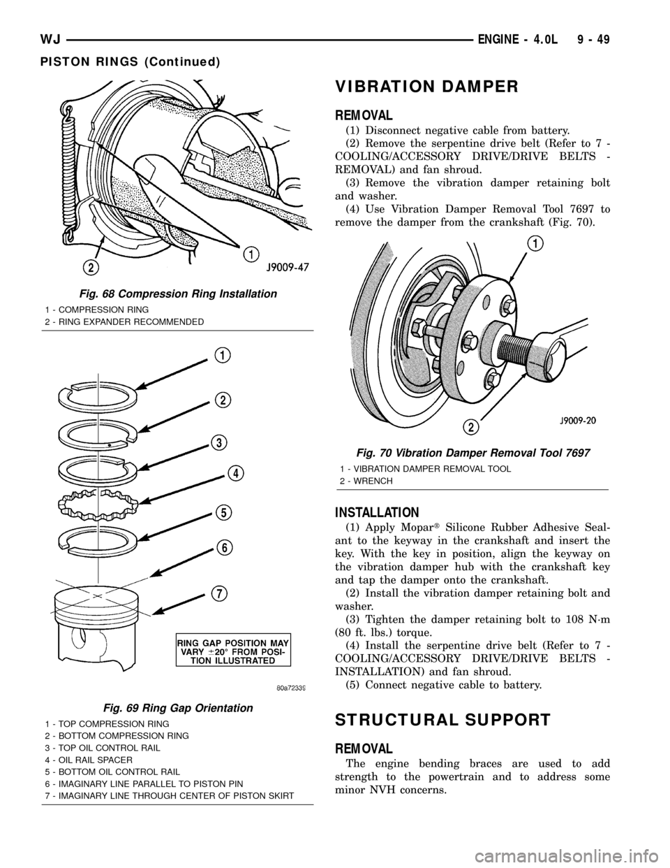
(4) Use Vibration Damper Removal Tool 7697 to
remove the damper from the crankshaft (Fig. 70).
INSTALLATION
(1) Apply MopartSilicone Rubber Adhesive Seal-
ant to the keyway in the crankshaft and insert the
key. With the key in position, align the keyway on
the vibration damper hub with the crankshaft key
and tap the damper onto the crankshaft.
(2) Install the vibration damper retaining bolt and
washer.
(3) Tighten the damper retaining bolt to 108 N´m
(80 ft. lbs.) torque.
(4) Install the serpentine drive belt (Refer to 7 -
COOLING/ACCESSORY DRIVE/DRIVE BELTS -
INSTALLATION) and fan shroud.
(5) Connect negative cable to battery.
STRUCTURAL SUPPORT
REMOVAL
The engine bending braces are used to add
strength to the powertrain and to address some
minor NVH concerns.
Fig. 68 Compression Ring Installation
1 - COMPRESSION RING
2 - RING EXPANDER RECOMMENDED
Fig. 69 Ring Gap Orientation
1 - TOP COMPRESSION RING
2 - BOTTOM COMPRESSION RING
3 - TOP OIL CONTROL RAIL
4 - OIL RAIL SPACER
5 - BOTTOM OIL CONTROL RAIL
6 - IMAGINARY LINE PARALLEL TO PISTON PIN
7 - IMAGINARY LINE THROUGH CENTER OF PISTON SKIRT
Fig. 70 Vibration Damper Removal Tool 7697
1 - VIBRATION DAMPER REMOVAL TOOL
2 - WRENCH
WJENGINE - 4.0L 9 - 49
PISTON RINGS (Continued)
Page 1293 of 2199
NOTE: Before the engine or the transmission can
be removed the engine bending braces must be
removed.
(1) Raise and support vehicle.
NOTE: Both left and right side bending braces are
removed the sameway. Only the right side is
shown.
NOTE: The exhaust does not require removal to
preform this procedure.
(2) Remove the exhaust hanger bracket retaining
bolt.
(3) Remove locknut and transmission bending
brace bar.
(4) Remove engine-to-bending brace retaining bolt,
bending brace bar and cross bar.
INSTALLATION
NOTE: DO NOT tighten the retaining hardware until
all bending braces are in place.
(1) Position the cross brace into the engine-to-
transmission brace, then position the engine-to-trans-
mission brace and install retaining bolt.
(2) Position the transmission bending brace onto
through brace and install new locknut.
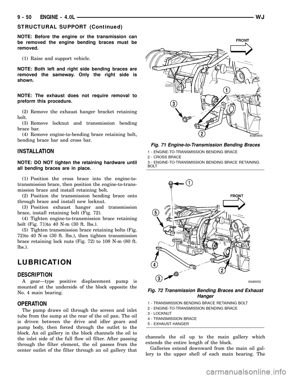
(3) Position exhaust hanger and transmission
brace, install retaining bolt (Fig. 72).
(4) Tighten engine-to-transmission brace retaining
bolt (Fig. 71)to 40 N´m (30 ft. lbs.).
(5) Tighten transmission brace retaining bolts (Fig.
72)to 40 N´m (30 ft. lbs.), then tighten transmission
brace retaining lock nuts (Fig. 72) to 108 N´m (80 ft.
lbs.).
LUBRICATION
DESCRIPTION
A gearÐtype positive displacement pump is
mounted at the underside of the block opposite the
No. 4 main bearing.
OPERATION
The pump draws oil through the screen and inlet
tube from the sump at the rear of the oil pan. The oil
is driven between the drive and idler gears and
pump body, then forced through the outlet to the
block. An oil gallery in the block channels the oil to
the inlet side of the full flow oil filter. After passing
through the filter element, the oil passes from the
center outlet of the filter through an oil gallery thatchannels the oil up to the main gallery which
extends the entire length of the block.
Galleries extend downward from the main oil gal-
lery to the upper shell of each main bearing. The
Fig. 71 Engine-to-Transmission Bending Braces
1 - ENGINE-TO-TRANSMISSION BENDING BRACE
2 - CROSS BRACE
3 - ENGINE-TO-TRANSMISSION BENDING BRACE RETAINING
BOLT
Fig. 72 Transmission Bending Braces and Exhaust
Hanger
1 - TRANSMISSION BENDING BRACE RETAINING BOLT
2 - ENGINE-TO-TRANSMISSION BENDING BRACE
3 - LOCKNUT
4 - TRANSMISSION BRACE
5 - EXHAUST HANGER
9 - 50 ENGINE - 4.0LWJ
STRUCTURAL SUPPORT (Continued)
Page 1296 of 2199
(5) If the leak is not detected, very slowly turn the
crankshaft and watch for leakage. If a leak is
detected between the crankshaft and seal while
slowly turning the crankshaft, it is possible the
crankshaft seal surface is damaged. The seal area on
the crankshaft could have minor nicks or scratches
that can be polished out with emery cloth.
CAUTION: Use extreme caution when crankshaft
polishing is necessary to remove minor nicks and
scratches. The crankshaft seal flange is especially
machined to complement the function of the rear oil
seal.
(6) For bubbles that remain steady with shaft
rotation, no further inspection can be done until dis-
assembled.
OIL
STANDARD PROCEDURE - ENGINE OIL
SERVICE
ENGINE OIL CHANGE
Change engine oil at mileage and time intervals
described in Maintenance Schedules.
Run engine until achieving normal operating tem-
perature.
(1) Position the vehicle on a level surface and turn
engine off.
(2) Hoist and support vehicle on safety stands.
(3) Remove oil fill cap.
(4) Place a suitable drain pan under crankcase
drain.
(5) Remove drain plug from crankcase and allow
oil to drain into pan. Inspect drain plug threads for
stretching or other damage. Replace drain plug if
damaged.
(6) Install drain plug in crankcase.
(7) Replace engine oil filter. (Refer to 9 - ENGINE/
LUBRICATION/OIL FILTER - REMOVAL).
(8) Lower vehicle and fill crankcase with specified
type of engine oil (Refer to LUBRICATION & MAIN-
TENANCE/FLUID TYPES - DESCRIPTION) and
amount of engine oil (Refer to LUBRICATION &
MAINTENANCE - SPECIFICATIONS).
(9) Install oil fill cap.
(10) Start engine and inspect for leaks.
(11) Stop engine and inspect oil level. Refer to
CRANKCASE OIL LEVEL INSPECTION .
USED ENGINE OIL DISPOSAL
Care should be exercised when disposing used
engine oil after it has been drained from a vehicle
engine.
CRANKCASE OIL LEVEL INSPECTION
CAUTION: Do not overfill crankcase with engine oil,
oil foaming and oil pressure loss can result.
The engine oil level indicator (Dipstick) is located
at the right rear of the 4.0L engine. Inspect engine
oil level approximately every 800 kilometers (500
miles). Unless the engine has exhibited loss of oil
pressure, run the engine for about five minutes
before checking oil level. Checking engine oil level on
a cold engine is not accurate.
To ensure proper lubrication of an engine, the
engine oil must be maintained at an acceptable level.
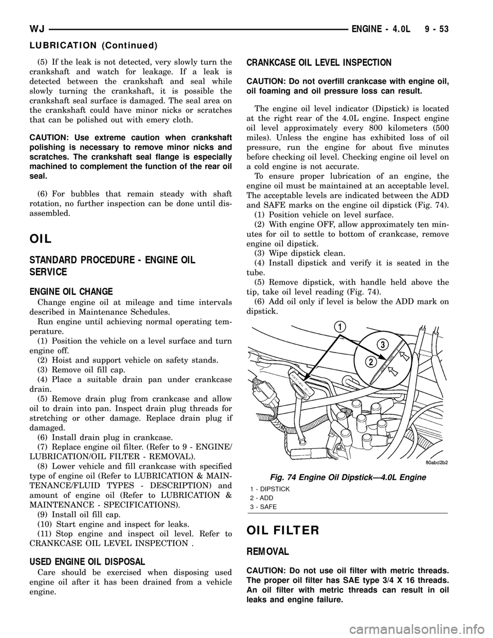
The acceptable levels are indicated between the ADD
and SAFE marks on the engine oil dipstick (Fig. 74).
(1) Position vehicle on level surface.
(2) With engine OFF, allow approximately ten min-
utes for oil to settle to bottom of crankcase, remove
engine oil dipstick.
(3) Wipe dipstick clean.
(4) Install dipstick and verify it is seated in the
tube.
(5) Remove dipstick, with handle held above the
tip, take oil level reading (Fig. 74).
(6) Add oil only if level is below the ADD mark on
dipstick.
OIL FILTER
REMOVAL
CAUTION: Do not use oil filter with metric threads.
The proper oil filter has SAE type 3/4 X 16 threads.
An oil filter with metric threads can result in oil
leaks and engine failure.
Fig. 74 Engine Oil DipstickÐ4.0L Engine
1 - DIPSTICK
2 - ADD
3 - SAFE
WJENGINE - 4.0L 9 - 53
LUBRICATION (Continued)
Page 1297 of 2199
All Jeep engines are equipped with a high quality
full-flow, throw-away type oil filter. DaimlerChrysler
Corporation recommends a Mopartor equivalent oil
filter be used.
(1) Position a drain pan under the oil filter.
(2) Using a suitable oil filter wrench loosen filter.
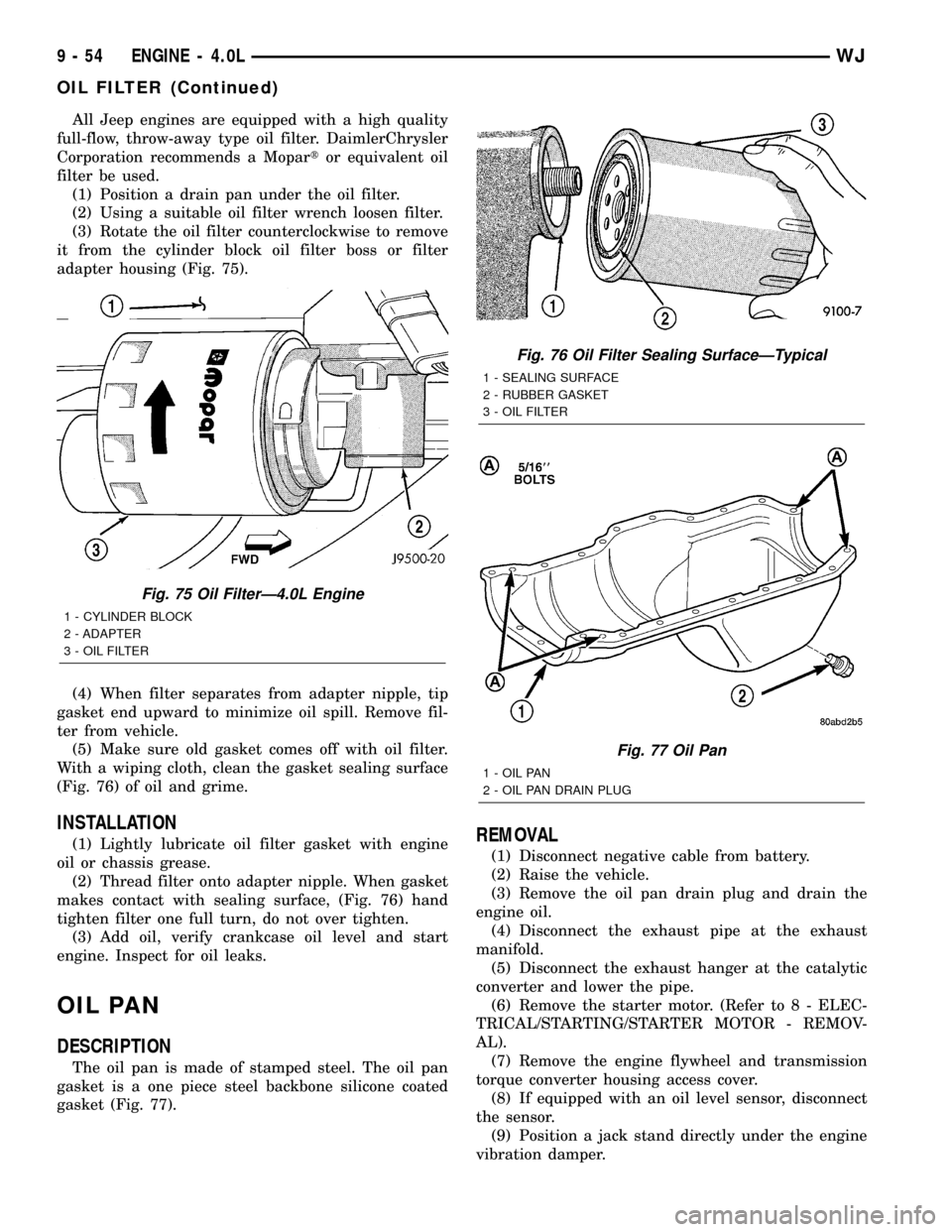
(3) Rotate the oil filter counterclockwise to remove
it from the cylinder block oil filter boss or filter
adapter housing (Fig. 75).
(4) When filter separates from adapter nipple, tip
gasket end upward to minimize oil spill. Remove fil-
ter from vehicle.
(5) Make sure old gasket comes off with oil filter.
With a wiping cloth, clean the gasket sealing surface
(Fig. 76) of oil and grime.
INSTALLATION
(1) Lightly lubricate oil filter gasket with engine
oil or chassis grease.
(2) Thread filter onto adapter nipple. When gasket
makes contact with sealing surface, (Fig. 76) hand
tighten filter one full turn, do not over tighten.
(3) Add oil, verify crankcase oil level and start
engine. Inspect for oil leaks.
OIL PAN
DESCRIPTION
The oil pan is made of stamped steel. The oil pan
gasket is a one piece steel backbone silicone coated
gasket (Fig. 77).
REMOVAL
(1) Disconnect negative cable from battery.
(2) Raise the vehicle.
(3) Remove the oil pan drain plug and drain the
engine oil.
(4) Disconnect the exhaust pipe at the exhaust
manifold.
(5) Disconnect the exhaust hanger at the catalytic
converter and lower the pipe.
(6) Remove the starter motor. (Refer to 8 - ELEC-
TRICAL/STARTING/STARTER MOTOR - REMOV-
AL).
(7) Remove the engine flywheel and transmission
torque converter housing access cover.
(8) If equipped with an oil level sensor, disconnect
the sensor.
(9) Position a jack stand directly under the engine
vibration damper.
Fig. 75 Oil FilterÐ4.0L Engine
1 - CYLINDER BLOCK
2 - ADAPTER
3 - OIL FILTER
Fig. 76 Oil Filter Sealing SurfaceÐTypical
1 - SEALING SURFACE
2 - RUBBER GASKET
3 - OIL FILTER
Fig. 77 Oil Pan
1 - OIL PAN
2 - OIL PAN DRAIN PLUG
9 - 54 ENGINE - 4.0LWJ
OIL FILTER (Continued)
Page 1298 of 2199
(10) Place a piece of wood (2 x 2) between the jack
stand and the engine vibration damper.
(11) Remove the engine mount through bolts.
(12) Using the jack stand, raise the engine until
adequate clearance is obtained to remove the oil pan.
(13) Remove transmission oil cooling lines (if
equipped) and oxygen sensor wiring supports that
are attached to the oil pan studs.
(14) Remove the oil pan bolts and studs. Carefully
slide the oil pan and gasket to the rear. If equipped
with an oil level sensor, take care not to damage the
sensor.
INSTALLATION
(1) Clean the block and pan gasket surfaces.
(2) Fabricate 4 alignment dowels from 1 1/2 x 1/4
inch bolts. Cut the head off the bolts and cut a slot
into the top of the dowel. This will allow easier
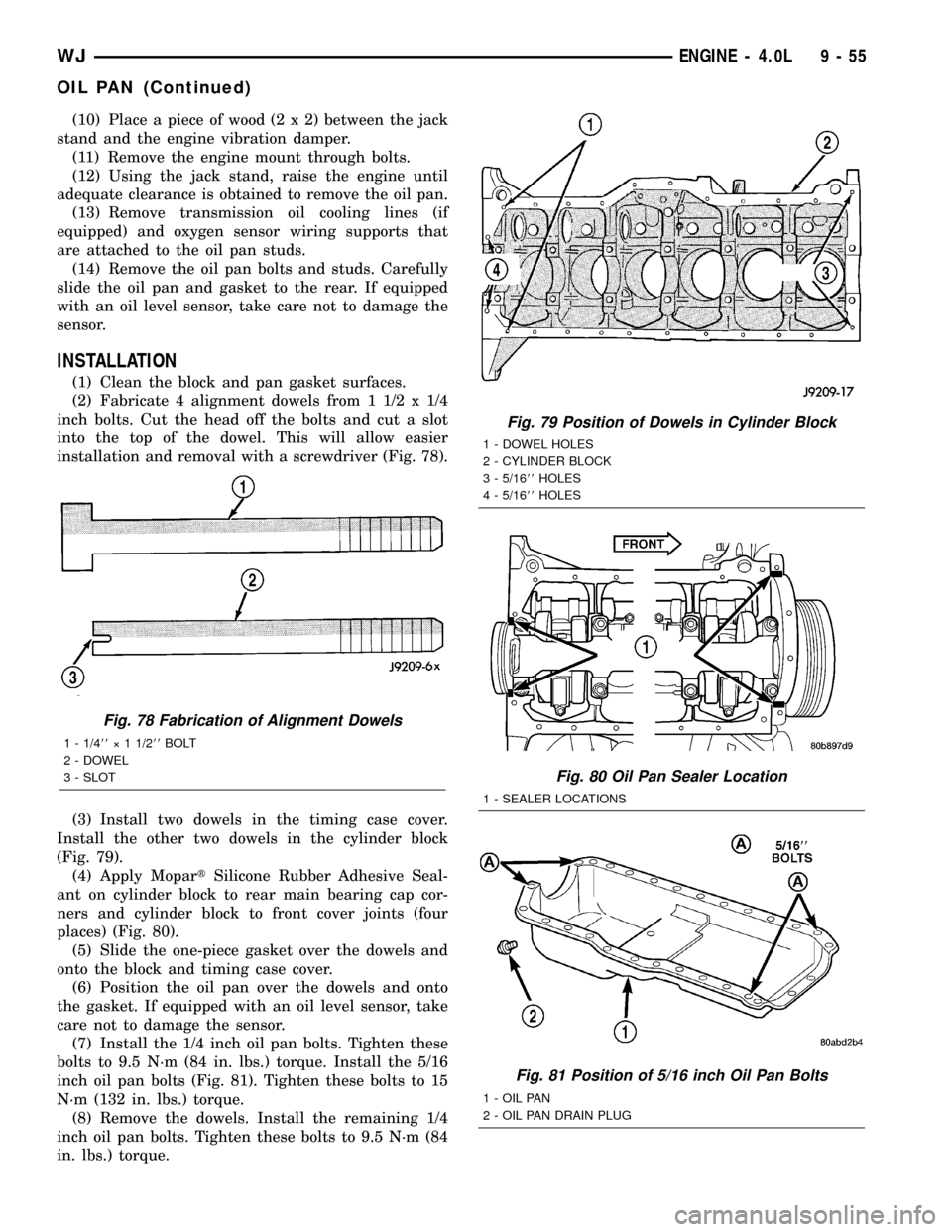
installation and removal with a screwdriver (Fig. 78).
(3) Install two dowels in the timing case cover.
Install the other two dowels in the cylinder block
(Fig. 79).
(4) Apply MopartSilicone Rubber Adhesive Seal-
ant on cylinder block to rear main bearing cap cor-
ners and cylinder block to front cover joints (four
places) (Fig. 80).
(5) Slide the one-piece gasket over the dowels and
onto the block and timing case cover.
(6) Position the oil pan over the dowels and onto
the gasket. If equipped with an oil level sensor, take
care not to damage the sensor.
(7) Install the 1/4 inch oil pan bolts. Tighten these
bolts to 9.5 N´m (84 in. lbs.) torque. Install the 5/16
inch oil pan bolts (Fig. 81). Tighten these bolts to 15
N´m (132 in. lbs.) torque.
(8) Remove the dowels. Install the remaining 1/4
inch oil pan bolts. Tighten these bolts to 9.5 N´m (84
in. lbs.) torque.
Fig. 78 Fabrication of Alignment Dowels
1 - 1/488ý 1 1/288BOLT
2 - DOWEL
3 - SLOT
Fig. 79 Position of Dowels in Cylinder Block
1 - DOWEL HOLES
2 - CYLINDER BLOCK
3 - 5/1688HOLES
4 - 5/1688HOLES
Fig. 80 Oil Pan Sealer Location
1 - SEALER LOCATIONS
Fig. 81 Position of 5/16 inch Oil Pan Bolts
1 - OIL PAN
2 - OIL PAN DRAIN PLUG
WJENGINE - 4.0L 9 - 55
OIL PAN (Continued)
Page 1299 of 2199
(9) Lower the engine until it is properly located on
the engine mounts.
(10) Install the through bolts and tighten the nuts.
(11) Lower the jack stand and remove the piece of
wood.
(12) Install the engine flywheel and transmission
torque converter housing access cover.
(13) Install the engine starter motor. (Refer to 8 -
ELECTRICAL/STARTING/STARTER MOTOR -
INSTALLATION).
(14) Connect the exhaust pipe to the hanger and to
the engine exhaust manifold.
(15) Install transmission oil cooling lines (if
equipped) and oxygen sensor wiring supports that
attach to the oil pan studs.
(16) Install the oil pan drain plug (Fig. 81).
Tighten the plug to 34 N´m (25 ft. lbs.) torque.
(17) Lower the vehicle.
(18) Connect negative cable to battery.
(19) Fill the oil pan with engine oil to the specified
level.
WARNING: USE EXTREME CAUTION WHEN THE
ENGINE IS OPERATING. DO NOT STAND IN A
DIRECT LINE WITH THE FAN. DO NOT PUT YOUR
HANDS NEAR THE PULLEYS, BELTS OR FAN. DO
NOT WEAR LOOSE CLOTHING.
(20) Start the engine and inspect for leaks.
ENGINE OIL PRESSURE
SENSOR
DESCRIPTION
The 3±wire, solid-state engine oil pressure sensor
(sending unit) is located in an engine oil pressure
gallery.
OPERATION
The oil pressure sensor uses three circuits. They
are:
²A 5±volt power supply from the Powertrain Con-
trol Module (PCM)
²A sensor ground through the PCM's sensor
return
²A signal to the PCM relating to engine oil pres-
sure
The oil pressure sensor has a 3±wire electrical
function very much like the Manifold Absolute Pres-
sure (MAP) sensor. Meaning different pressures
relate to different output voltages.
A 5±volt supply is sent to the sensor from the PCM
to power up the sensor. The sensor returns a voltage
signal back to the PCM relating to engine oil pres-
sure. This signal is then transferred (bussed) to theinstrument panel on either a CCD or PCI bus circuit
(depending on vehicle line) to operate the oil pressure
gauge and the check gauges lamp. Ground for the
sensor is provided by the PCM through a low-noise
sensor return.
OIL PUMP
REMOVAL
A gear-type oil pump is mounted at the underside
of the cylinder block opposite the No.4 main bearing.
(1) Drain the engine oil.
(2) Remove the oil pan (Refer to 9 - ENGINE/LU-
BRICATION/OIL PAN - REMOVAL).
(3) Remove the pump-to-cylinder block attaching
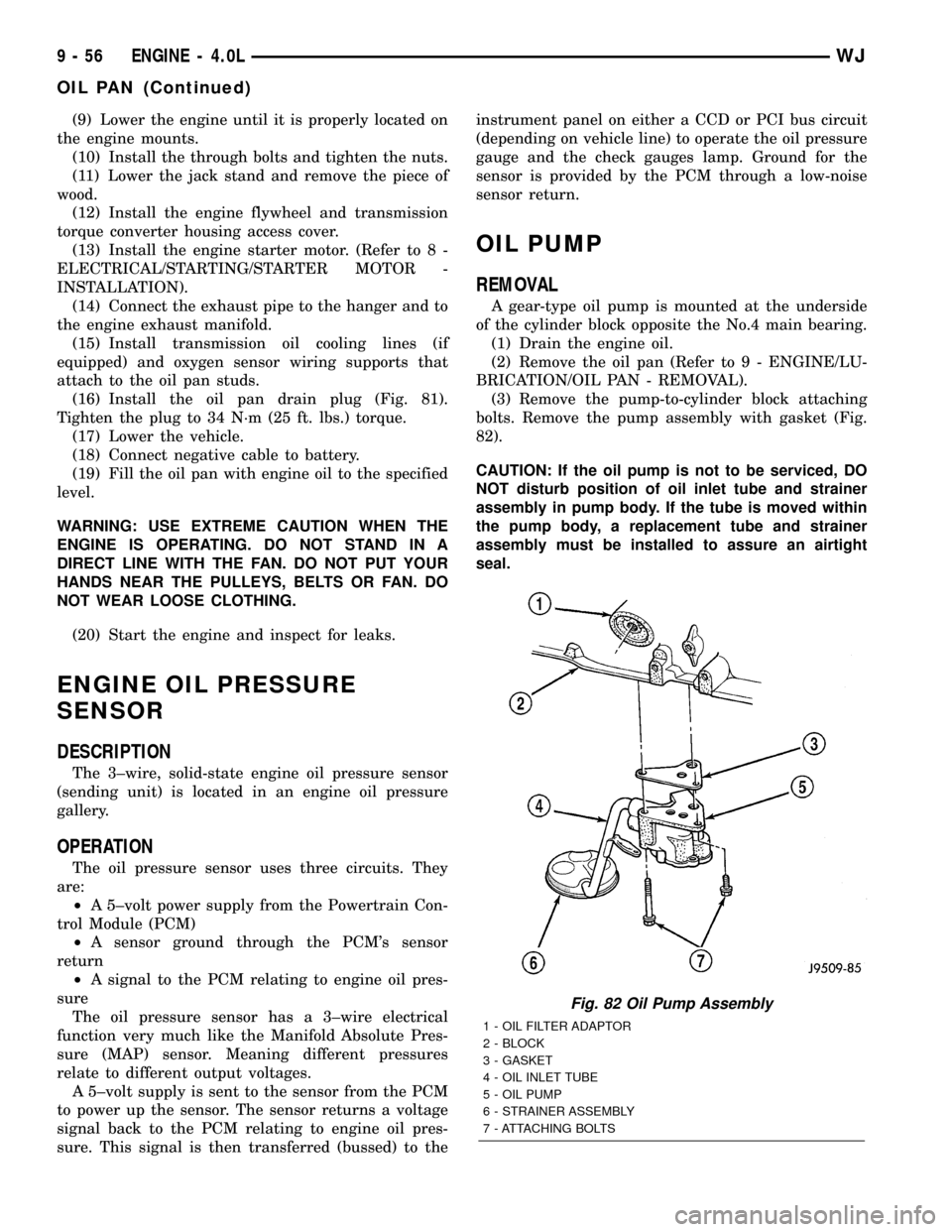
bolts. Remove the pump assembly with gasket (Fig.
82).
CAUTION: If the oil pump is not to be serviced, DO
NOT disturb position of oil inlet tube and strainer
assembly in pump body. If the tube is moved within
the pump body, a replacement tube and strainer
assembly must be installed to assure an airtight
seal.
Fig. 82 Oil Pump Assembly
1 - OIL FILTER ADAPTOR
2 - BLOCK
3 - GASKET
4 - OIL INLET TUBE
5 - OIL PUMP
6 - STRAINER ASSEMBLY
7 - ATTACHING BOLTS
9 - 56 ENGINE - 4.0LWJ
OIL PAN (Continued)