2002 JEEP GRAND CHEROKEE Oil pan removal
[x] Cancel search: Oil pan removalPage 501 of 2199

the engine compartment. This relay can be energized
by the BCM to sound the horns as an audible alert
for the RKE panic function and, if the Sound Horn
on Lock programmable feature is enabled, as an
audible verification for the RKE lock event. (Refer to
8 - ELECTRICAL/HORN/HORN RELAY - DESCRIP-
TION).
LOW BEAM HEADLAMP RELAY
The low beam headlamp relay is a electromechan-
ical device that switches battery current to the head-
lamp low beams when the BCM grounds the relay
coil. The low beam headlamp relay is located in the
junction block in the passenger compartment. This
relay can be energized by the BCM to flash the head-
lamp low beams as an optical alert for the RKE panic
function. (Refer to 8 - ELECTRICAL/LAMPS/LIGHT-
ING - EXTERIOR/HEADLAMP - DESCRIPTION).
DESCRIPTION - LIFTGATE FLIP-UP GLASS
POWER RELEASE SYSTEM
A power operated liftgate flip-up glass release sys-
tem is standard factory installed equipment on this
model. The liftgate flip-up glass power release system
allows the flip-up glass latch to be released electri-
cally by depressing a switch located on the bottom of
the liftgate license plate lamp housing unit, above
the license plate on the outside of the liftgate.
The liftgate flip-up glass release system operates
on non-switched battery current supplied through a
fuse in the junction block so that the system remains
functional, regardless of the ignition switch position.
However, a limit switch that is integral to the liftgate
latch actuator unit opens to prevent the flip-up glass
latch from being actuated when the liftgate latch is
locked.
The liftgate flip-up glass power release system
includes the following components:
²Liftgate Flip-Up Glass Limit Switch- The
liftgate flip-up glass limit switch is integral to the
liftgate latch unit. (Refer to 23 - BODY/DECKLID/
HATCH/LIFTGATE/TAILGATE/LATCH - REMOVAL)
and (Refer to 23 - BODY/DECKLID/HATCH/LIFT-
GATE/TAILGATE/LATCH - INSTALLATION).
²Liftgate Flip-Up Glass Release Motor- The
liftgate flip-up glass release motor is integral to the
liftgate flip-up glass latch unit. (Refer to 23 - BODY/
DECKLID/HATCH/LIFTGATE/TAILGATE/FLIP-UP
GLASS LATCH - REMOVAL) and (Refer to 23 -
BODY/DECKLID/HATCH/LIFTGATE/TAILGATE/
FLIP-UP GLASS LATCH - INSTALLATION).
²Liftgate Flip-Up Glass Release Switch- The
liftgate flip-up glass release switch is integral to the
liftgate license plate lamp housing. (Refer to 23 -
BODY/DECKLID/HATCH/LIFTGATE/TAILGATE/
FLIP-UP GLASS SWITCH - REMOVAL) and (Referto 23 - BODY/DECKLID/HATCH/LIFTGATE/TAIL-
GATE/FLIP-UP GLASS SWITCH - INSTALLATION).
Hard wired circuitry connects the liftgate flip-up
glass power release system components to the electri-
cal system of the vehicle. These hard wired circuits
are integral to several wire harnesses, which are
routed throughout the vehicle and retained by many
different methods. These circuits may be connected to
each other, to the vehicle electrical system and to the
liftgate flip-up glass power release system compo-
nents through the use of a combination of soldered
splices, splice block connectors, and many different
types of wire harness terminal connectors and insu-
lators. Refer to the appropriate wiring information.
The wiring information includes wiring diagrams,
proper wire and connector repair procedures, further
details on wire harness routing and retention, as well
as pin-out and location views for the various wire
harness connectors, splices and grounds.OPERATION
OPERATION - POWER LOCK SYSTEM
The Passenger Door Module (PDM) contains the
power door lock control logic and a power lock switch.
The Driver Door Module (DDM) contains a power
lock switch and controls the output to the driver side
front door power lock motor, while the PDM controls
the output to the power lock motors for the remain-
ing doors and the liftgate.
When the power lock switch on the DDM is used to
lock or unlock the doors, the DDM sends a control
output to the driver side front door power lock motor
and sends lock or unlock request messages to the
PDM over the Programmable Communications Inter-
face (PCI) data bus. The PDM responds to these mes-
sages by sending control outputs to the power lock
motors of the remaining doors and the liftgate. When
the power lock switch on the PDM is used to lock or
unlock the doors, the PDM sends control outputs to
the power lock motors in the passenger side front
door, both rear doors and the liftgate, then sends lock
or unlock request messages to the DDM over the Pro-
grammable Communications Interface (PCI) data
bus. The DDM responds to these messages by send-
ing control outputs to the power lock motor of the
driver side front door.
In order to support the auto door locks and unlock
on exit features, if enabled, the power lock system
logic in the PDM needs to know the door ajar switch
status, vehicle speed, and transmission gear selector
lever position. The passenger side front door ajar
switch is the only hard wired input to the PDM. The
PDM obtains the remaining information from mes-
sages it receives from other electronic modules over
the PCI data bus network.
8N - 4 POWER LOCKSWJ
POWER LOCKS (Continued)
Page 616 of 2199

WASHER SYSTEM
The washer system components should be
inspected periodically, not just when washer perfor-
mance problems are experienced. This inspection
should include the following points:
(1) Check for ice or other foreign material in the
washer reservoir. If contaminated, clean and flush
the washer system. (Refer to 8 - ELECTRICAL/
FRONT WIPERS/WASHERS - CLEANING).
(2) Inspect the washer plumbing for pinched, leak-
ing, deteriorated, or incorrectly routed hoses and
damaged or disconnected hose fittings. Replace dam-
aged or deteriorated hoses and hose fittings. Leaking
washer hoses can sometimes be repaired by cutting
the hose at the leak and splicing it back together
using an in-line connector fitting. Similarly, sections
of deteriorated hose can be cut out and replaced by
splicing in new sections of hose using in-line connec-
tor fittings. Whenever routing a washer hose or a
wire harness containing a washer hose, it must be
routed away from hot, sharp, or moving parts. Also,
sharp bends that might pinch the washer hose must
be avoided.
FRONT CHECK VALVE
DESCRIPTION
A front washer system check valve is standard
equipment on this model. The front check valve is
integral to the front washer nozzle plumbing wye fit-
ting located in the cowl plenum beneath the cowl ple-
num cover/grille panel near the base of the
windshield. The check valve consists of a molded
plastic body with a round center section. Three
barbed hose nipples are formed in a wye configura-
tion on the outside circumference of the center sec-
tion of the valve body. Within the check valve body, a
small check valve operated by a small coiled spring
restricts flow through the unit until the valve is
unseated by a predetermined inlet fluid pressure.
The front check valve cannot be adjusted or repaired
and, if faulty or damaged, it must be replaced.
OPERATION
The front check valve provides more than one func-
tion in this application. It serves as a wye connector
fitting between the cowl grille panel and washer noz-
zle sections of the front washer supply hose. It also
prevents washer fluid from draining out of the front
washer supply hoses back to the washer reservoir.
This drain-back would result in a lengthy delay from
when the front washer switch is actuated until
washer fluid was dispensed through the front washer
nozzles, because the front washer pump would have
to refill the front washer plumbing from the reservoir
to the nozzles. Finally, the front check valve prevents
washer fluid from siphoning through the front
washer nozzles after the front washer system is
turned Off. When the front washer pump pressurizes
and pumps washer fluid from the reservoir through
the front washer plumbing, the fluid pressure over-
rides the spring pressure applied to the check valve
and unseats the valve, allowing washer fluid to flow
toward the front washer nozzles. When the front
washer pump stops operating, spring pressure seats
the check valve and fluid flow in either direction
within the front washer plumbing is prevented.
REMOVAL
(1) Disconnect and isolate the battery negative
cable.
(2) Remove the wiper arms from the wiper pivots.
(Refer to 8 - ELECTRICAL/FRONT WIPERS/WASH-
ERS/FRONT WIPER ARMS - REMOVAL).
(3) Open the hood and pull the hood to plenum
seal off of the forward flanges of the cowl grille cover
and the plenum panel.
Fig. 2 Wiper Blade Inspection
1 - WORN OR UNEVEN EDGES
2 - ROAD FILM OR FOREIGN MATERIAL DEPOSITS
3 - HARD, BRITTLE, OR CRACKED
4 - DEFORMED OR FATIGUED
5 - SPLIT
6 - DAMAGED SUPPORT COMPONENTS
WJFRONT WIPERS/WASHERS 8R - 9
FRONT WIPERS/WASHERS (Continued)
Page 646 of 2199

along the left roof side rail to the rear of the vehicle.
At the rear of the vehicle, the headliner hose is
routed above the headliner and along the upper lift-
gate opening panel toward the right side of the vehi-
cle. The headliner hose then passes through a hole
with a rubber grommet in the upper liftgate opening
panel and through another hole with a rubber grom-
met into the upper inner liftgate panel to the rear
washer nozzle.
Washer hose is available for service only as roll
stock, which must then be cut to length. The head-
liner washer hose is integral to the headliner unit
and, if faulty or damaged, the headliner unit must be
replaced. The molded plastic washer hose fittings
cannot be repaired. If these fittings are faulty or
damaged, they must be replaced.
OPERATION
Washer fluid in the washer reservoir is pressurized
and fed by the rear washer pump/motor through the
rear washer system plumbing and fittings to the rear
washer nozzle on the liftgate outer panel above the
liftgate glass. Whenever routing the washer hose or a
wire harness containing a washer hose, it must be
routed away from hot, sharp, or moving parts; and,
sharp bends that might pinch the hose must be
avoided.
REAR WASHER NOZZLE
DESCRIPTION
The rear washer nozzle is a fluidic type unit that
includes an integral check valve (Fig. 3). The nozzle
is constructed of molded plastic and has a rubber
seal and integral snap features on the back of it. The
nozzle is secured by a snap fit in a dedicated mount-
ing hole in the liftgate outer panel above the liftgate
flip-up glass. Within the rear nozzle body, a small
check ball is held against an integral valve seat at
the inlet end of the nozzle by a small coiled spring.
The rear washer nozzle and check valve unit cannot
be adjusted or repaired. If faulty or damaged, the
entire nozzle and check valve unit must be replaced.
OPERATION
The rear washer nozzle is designed to dispense
washer fluid into the wiper pattern area on the out-
side of the liftgate glass. Pressurized washer fluid is
fed to the nozzle from the washer reservoir by the
rear washer pump/motor through a single hose,
which is attached to a barbed nipple on the back of
the rear washer nozzle. The rear washer nozzle
incorporates a fluidic design, which causes the nozzle
to emit the pressurized washer fluid as an oscillating
stream to more effectively cover a larger area of the
glass area to be cleaned. The integral rear nozzle
check valve prevents washer fluid from draining out
of the rear washer supply hoses back to the washer
reservoir. This drain-back would result in a lengthy
delay from when the rear washer switch is actuated
until washer fluid was dispensed through the rear
washer nozzle, because the rear washer pump would
have to refill the rear washer plumbing from the res-
ervoir to the nozzle. The check valve also prevents
washer fluid from siphoning through the rear washer
nozzle after the rear washer system is turned Off.
When the rear washer pump pressurizes and pumps
washer fluid from the reservoir through the rear
washer plumbing, the fluid pressure overrides the
spring pressure applied to the check ball within the
valve and unseats the check ball, allowing washer
fluid to flow to the rear washer nozzle. When the
rear washer pump stops operating, spring pressure
seats the check ball in the valve and fluid flow in
either direction within the rear washer plumbing is
prevented.
REMOVAL
The check valve for the rear washer nozzle is inte-
gral to the nozzle.
(1) Using a trim stick or another suitable wide
flat-bladed tool, gently pry at the sides of the rear
washer nozzle to release the snap features that
secure it in the mounting hole of the liftgate outer
panel.
Fig. 3 Rear Washer Nozzle
1 - HEADLINER WASHER HOSE
2 - ROOF PANEL
3 - REAR WASHER NOZZLE
4 - LIFTGATE
WJREAR WIPERS/WASHERS 8R - 39
REAR WASHER HOSES/TUBES (Continued)
Page 1245 of 2199
REMOVAL
REMOVAL - CAMSHAFT BEARINGS.......31
REMOVAL - CAMSHAFT................31
INSPECTION
INSPECTION - CAMSHAFT BEARINGS.....31
INSPECTION - CAMSHAFT..............31
INSTALLATION
INSTALLATION - CAMSHAFT BEARINGS . . . 32
INSTALLATION - CAMSHAFT............32
CONNECTING ROD BEARINGS
STANDARD PROCEDURE - FITTING
CONNECTING ROD BEARINGS..........33
CRANKSHAFT
DESCRIPTION.........................35
CRANKSHAFT MAIN BEARINGS
STANDARD PROCEDURE - FITTING
CRANKSHAFT MAIN BEARINGS..........36
REMOVAL.............................39
INSPECTION..........................40
INSTALLATION.........................40
CRANKSHAFT OIL SEAL - FRONT
REMOVAL.............................41
INSTALLATION.........................41
CRANKSHAFT OIL SEAL - REAR
REMOVAL.............................42
INSTALLATION.........................42
HYDRAULIC LIFTERS
DESCRIPTION.........................43
REMOVAL.............................43
CLEANING............................43
INSPECTION..........................43
INSTALLATION.........................43
PISTON & CONNECTING ROD
DESCRIPTION.........................44
STANDARD PROCEDURE - PISTON FITTING . 44
REMOVAL.............................45
INSTALLATION.........................46
PISTON RINGS
STANDARD PROCEDURE - PISTON RING
FITTING.............................47
VIBRATION DAMPER
REMOVAL.............................49
INSTALLATION.........................49STRUCTURAL SUPPORT
REMOVAL.............................49
INSTALLATION.........................50
LUBRICATION
DESCRIPTION.........................50
OPERATION...........................50
DIAGNOSIS AND TESTING
DIAGNOSIS AND TESTING - ENGINE OIL
PRESSURE..........................51
DIAGNOSIS AND TESTING - ENGINE OIL
LEAK...............................51
OIL
STANDARD PROCEDURE - ENGINE OIL
SERVICE............................53
OIL FILTER
REMOVAL.............................53
INSTALLATION.........................54
OIL PAN
DESCRIPTION.........................54
REMOVAL.............................54
INSTALLATION.........................55
ENGINE OIL PRESSURE SENSOR
DESCRIPTION.........................56
OPERATION...........................56
OIL PUMP
REMOVAL.............................56
INSTALLATION.........................57
INTAKE MANIFOLD
DESCRIPTION.........................57
DIAGNOSIS AND TESTING - INTAKE
MANIFOLD LEAKAGE..................57
REMOVAL.............................57
INSTALLATION.........................57
EXHAUST MANIFOLD
DESCRIPTION.........................58
REMOVAL.............................58
INSTALLATION.........................58
TIMING BELT / CHAIN COVER(S)
REMOVAL.............................58
INSTALLATION.........................58
TIMING BELT/CHAIN AND SPROCKETS
REMOVAL.............................60
INSTALLATION.........................60
ENGINE - 4.0L
DESCRIPTION
The 4.0 Liter (242 CID) six-cylinder engine is an
In-line, lightweight, overhead valve engine. This
engine is designed for unleaded fuel.
The engine cylinder head has dual quench-type
combustion chambers that create turbulence and fast
burning of the air/fuel mixture. This results in better
fuel economy.
The cylinders are numbered 1 through 6 from front
to rear. The firing order is 1-5-3-6-2-4 (Fig. 1).The crankshaft rotation is clockwise, when viewed
from the front of the engine. The crankshaft rotates
within seven main bearings. The camshaft rotates
within four bearings.
The engine Build Date Code is located on a
machined surface on the right side of the cylinder
block between the No.2 and No.3 cylinders (Fig. 2).
The digits of the code identify:
²1st DigitÐThe year (8 = 1998).
²2nd & 3rd DigitsÐThe month (01 - 12).
²4th & 5th DigitsÐThe engine type/fuel system/
compression ratio (MX = A 4.0 Liter (242 CID) 8.7:1
compression ratio engine with a multi-point fuel
injection system).
9 - 2 ENGINE - 4.0LWJ
Page 1254 of 2199
CAUTION: DO NOT use engine or transmission oil,
mineral spirits, or kerosene.
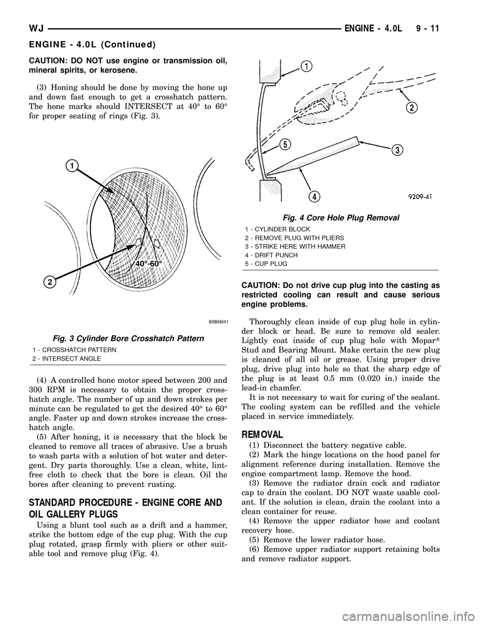
(3) Honing should be done by moving the hone up
and down fast enough to get a crosshatch pattern.
The hone marks should INTERSECT at 40É to 60É
for proper seating of rings (Fig. 3).
(4) A controlled hone motor speed between 200 and
300 RPM is necessary to obtain the proper cross-
hatch angle. The number of up and down strokes per
minute can be regulated to get the desired 40É to 60É
angle. Faster up and down strokes increase the cross-
hatch angle.
(5) After honing, it is necessary that the block be
cleaned to remove all traces of abrasive. Use a brush
to wash parts with a solution of hot water and deter-
gent. Dry parts thoroughly. Use a clean, white, lint-
free cloth to check that the bore is clean. Oil the
bores after cleaning to prevent rusting.
STANDARD PROCEDURE - ENGINE CORE AND
OIL GALLERY PLUGS
Using a blunt tool such as a drift and a hammer,
strike the bottom edge of the cup plug. With the cup
plug rotated, grasp firmly with pliers or other suit-
able tool and remove plug (Fig. 4).CAUTION: Do not drive cup plug into the casting as
restricted cooling can result and cause serious
engine problems.
Thoroughly clean inside of cup plug hole in cylin-
der block or head. Be sure to remove old sealer.
Lightly coat inside of cup plug hole with Mopart
Stud and Bearing Mount. Make certain the new plug
is cleaned of all oil or grease. Using proper drive
plug, drive plug into hole so that the sharp edge of
the plug is at least 0.5 mm (0.020 in.) inside the
lead-in chamfer.
It is not necessary to wait for curing of the sealant.
The cooling system can be refilled and the vehicle
placed in service immediately.
REMOVAL
(1) Disconnect the battery negative cable.
(2) Mark the hinge locations on the hood panel for
alignment reference during installation. Remove the
engine compartment lamp. Remove the hood.
(3) Remove the radiator drain cock and radiator
cap to drain the coolant. DO NOT waste usable cool-
ant. If the solution is clean, drain the coolant into a
clean container for reuse.
(4) Remove the upper radiator hose and coolant
recovery hose.
(5) Remove the lower radiator hose.
(6) Remove upper radiator support retaining bolts
and remove radiator support.
Fig. 3 Cylinder Bore Crosshatch Pattern
1 - CROSSHATCH PATTERN
2 - INTERSECT ANGLE
Fig. 4 Core Hole Plug Removal
1 - CYLINDER BLOCK
2 - REMOVE PLUG WITH PLIERS
3 - STRIKE HERE WITH HAMMER
4 - DRIFT PUNCH
5 - CUP PLUG
WJENGINE - 4.0L 9 - 11
ENGINE - 4.0L (Continued)
Page 1261 of 2199
DESCRIPTION N´m Ft. In.
Lbs. Lbs.
Transmission Support Bracket
ÐBolt (Manual) 46 34 Ð
Transmission Support Bracket/
CushionÐBolt (4WD Auto) 75 55 Ð
Transmission Support Adaptor
BracketÐBolts (2WD Auto) 75 55 Ð
Exhaust Manifold/PipeÐNuts 27 20 Ð
Intake/Exhaust Manifold
Fasteners #1-5 33 24 Ð
Fasteners #6 and 7 14 Ð 126
Fasteners #8-11 33 24 Ð
Flywheel to Converter
HousingÐBolts38 28 Ð
Flywheel to CrankshaftÐBolts 143 105 Ð
Front Cover to BlockÐBolts
1/4-20 7 Ð 60
5/16-18 22 Ð 192
Fuel RailÐBolts/Stud 12 Ð 108
GeneratorÐBolts 57 42 Ð
Generator Bracket to EngineÐ
Bolts47 35 Ð
Idler Pulley to Cylinder
HeadÐBolt47 35 Ð
Main Bearing CapÐBolts 108 80 Ð
Oil Filter 18 Ð 156
Oil Filter Connector to
Adaptor 47 35 Ð
Block 68 50 Ð
Adaptor Bolts 102 50 Ð
Oil GalleyÐPlug 41 30 Ð
Oil PanÐBolts
1/4-20 9.5 Ð 84
5/16-18 15 Ð 132
Oil PanÐDrain Plug 34 25 Ð
Oil Pump
Mounting Bolts 23 Ð 204
Cover Bolts 8 Ð 70
Rocker Arm Assembly to
Cylinder
HeadÐCapscrews 30 21 Ð
Spark Plugs 37 27 ÐDESCRIPTION N´m Ft. In.
Lbs. Lbs.
Starter MotorÐMounting Bolts 45 33 Ð
Thermostat HousingÐBolts 18 Ð 156
Throttle BodyÐBolts 10 Ð 90
Vibration DamperÐBolt 108 80 Ð
Water Pump to BlockÐBolts 23 17 Ð
AIR CLEANER ELEMENT
REMOVAL - 4.0L
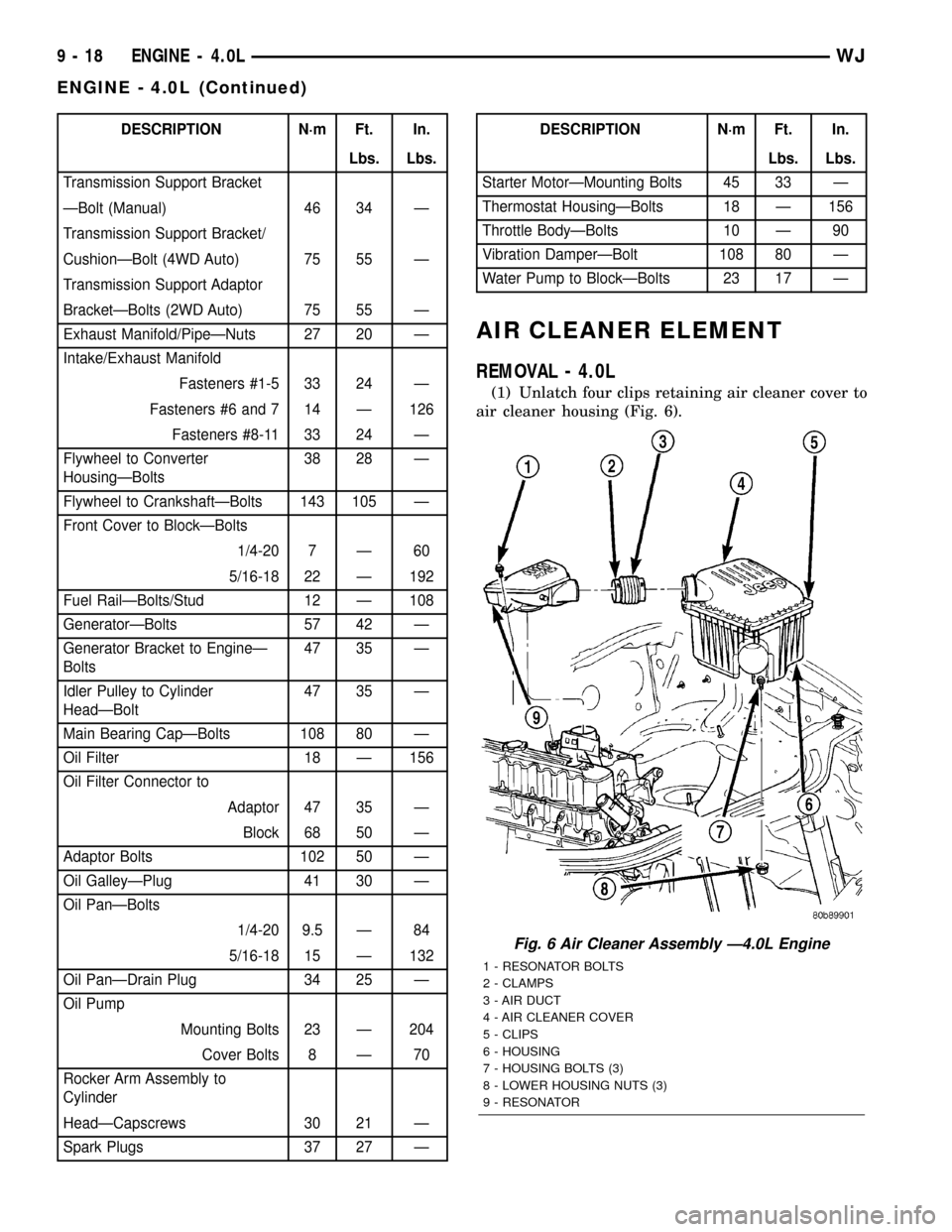
(1) Unlatch four clips retaining air cleaner cover to
air cleaner housing (Fig. 6).
Fig. 6 Air Cleaner Assembly Ð4.0L Engine
1 - RESONATOR BOLTS
2 - CLAMPS
3 - AIR DUCT
4 - AIR CLEANER COVER
5 - CLIPS
6 - HOUSING
7 - HOUSING BOLTS (3)
8 - LOWER HOUSING NUTS (3)
9 - RESONATOR
9 - 18 ENGINE - 4.0LWJ
ENGINE - 4.0L (Continued)
Page 1282 of 2199
REMOVAL
(1) Disconnect negative cable from battery.
(2) Remove the spark plugs (Refer to 8 - ELEC-
TRICAL/IGNITION CONTROL/SPARK PLUG -
REMOVAL).
(3) Raise the vehicle.
(4) Remove the oil pan (Refer to 9 - ENGINE/LU-
BRICATION/OIL PAN - REMOVAL) and oil pump
(Refer to 9 - ENGINE/LUBRICATION/OIL PUMP -
REMOVAL).
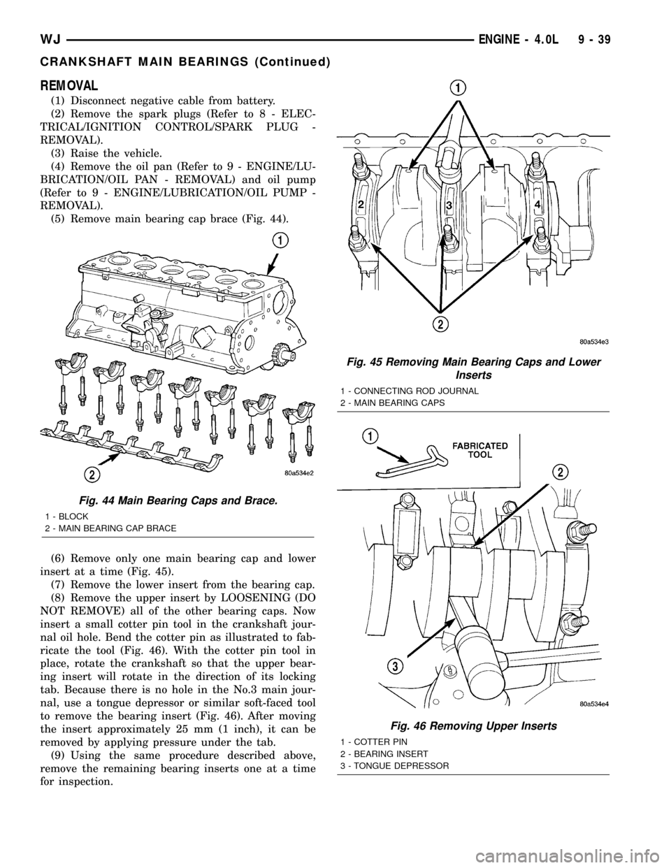
(5) Remove main bearing cap brace (Fig. 44).
(6) Remove only one main bearing cap and lower
insert at a time (Fig. 45).
(7) Remove the lower insert from the bearing cap.
(8) Remove the upper insert by LOOSENING (DO
NOT REMOVE) all of the other bearing caps. Now
insert a small cotter pin tool in the crankshaft jour-
nal oil hole. Bend the cotter pin as illustrated to fab-
ricate the tool (Fig. 46). With the cotter pin tool in
place, rotate the crankshaft so that the upper bear-
ing insert will rotate in the direction of its locking
tab. Because there is no hole in the No.3 main jour-
nal, use a tongue depressor or similar soft-faced tool
to remove the bearing insert (Fig. 46). After moving
the insert approximately 25 mm (1 inch), it can be
removed by applying pressure under the tab.
(9) Using the same procedure described above,
remove the remaining bearing inserts one at a time
for inspection.
Fig. 44 Main Bearing Caps and Brace.
1 - BLOCK
2 - MAIN BEARING CAP BRACE
Fig. 45 Removing Main Bearing Caps and Lower
Inserts
1 - CONNECTING ROD JOURNAL
2 - MAIN BEARING CAPS
Fig. 46 Removing Upper Inserts
1 - COTTER PIN
2 - BEARING INSERT
3 - TONGUE DEPRESSOR
WJENGINE - 4.0L 9 - 39
CRANKSHAFT MAIN BEARINGS (Continued)
Page 1284 of 2199
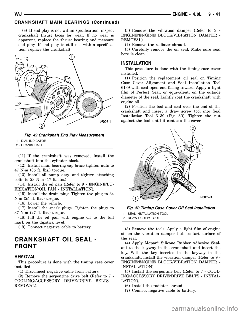
(e) If end play is not within specification, inspect
crankshaft thrust faces for wear. If no wear is
apparent, replace the thrust bearing and measure
end play. If end play is still not within specifica-
tion, replace the crankshaft.
(11) If the crankshaft was removed, install the
crankshaft into the cylinder block.
(12) Install main bearing cap brace tighten nuts to
47 N´m (35 ft. lbs.) torque.
(13) Install oil pump assy. and tighten attaching
bolts to 23 N´m (17 ft. lbs.)
(14) Install the oil pan (Refer to 9 - ENGINE/LU-
BRICATION/OIL PAN - INSTALLATION).
(15) Install the drain plug. Tighten the plug to 34
N´m (25 ft. lbs.) torque.
(16) Lower the vehicle.
(17) Install the spark plugs. Tighten the plugs to
37 N´m (27 ft. lbs.) torque.
(18) Fill the oil pan with engine oil to the full
mark on the dipstick level.
(19) Connect negative cable to battery.
CRANKSHAFT OIL SEAL -
FRONT
REMOVAL
This procedure is done with the timing case cover
installed.
(1) Disconnect negative cable from battery.
(2) Remove the serpentine drive belt (Refer to 7 -
COOLING/ACCESSORY DRIVE/DRIVE BELTS -
REMOVAL).(3) Remove the vibration damper (Refer to 9 -
ENGINE/ENGINE BLOCK/VIBRATION DAMPER -
REMOVAL).
(4) Remove the radiator shroud.
(5) Carefully remove the oil seal. Make sure seal
bore is clean.
INSTALLATION
This procedure is done with the timing case cover
installed.
(1) Position the replacement oil seal on Timing
Case Cover Alignment and Seal Installation Tool
6139 with seal open end facing inward. Apply a light
film of Perfect Seal, or equivalent, on the outside
diameter of the seal. Lightly coat the crankshaft with
engine oil.
(2) Position the tool and seal over the end of the
crankshaft and insert a draw screw tool into Seal
Installation Tool 6139 (Fig. 50). Tighten the nut
against the tool until it contacts the cover.
(3) Remove the tools. Apply a light film of engine
oil on the vibration damper hub contact surface of
the seal.
(4) Apply MopartSilicone Rubber Adhesive Seal-
ant to the keyway in the crankshaft and insert the
key. With the key inserted in the keyway in the
crankshaft, install the vibration damper (Refer to 9 -
ENGINE/ENGINE BLOCK/VIBRATION DAMPER -
INSTALLATION).
(5) Install the serpentine belt (Refer to 7 - COOL-
ING/ACCESSORY DRIVE/DRIVE BELTS - INSTAL-
LATION).
(6) Install the radiator shroud.
(7) Connect negative cable to battery.
Fig. 49 Crankshaft End Play Measurement
1 - DIAL INDICATOR
2 - CRANKSHAFT
Fig. 50 Timing Case Cover Oil Seal Installation
1 - SEAL INSTALLATION TOOL
2 - DRAW SCREW TOOL
WJENGINE - 4.0L 9 - 41
CRANKSHAFT MAIN BEARINGS (Continued)