2002 JEEP GRAND CHEROKEE Indicator
[x] Cancel search: IndicatorPage 147 of 2199
(14) Remove differential case and dummy bearings
from the housing.
(15) Install the pinion gear in the housing. Install
the pinion yoke and establish the correct pinion
rotating torque.
(16) Install differential case and Dummy Bearings
6929-A in the housing.
(17) Install a single dummy shim in the ring gear
side. Install bearing caps and tighten bolts snug.
(18) Seat ring gear side dummy bearing (Fig. 16).
(19) Position the dial indicator plunger on a flat
surface between the ring gear bolt heads. (Fig. 17).
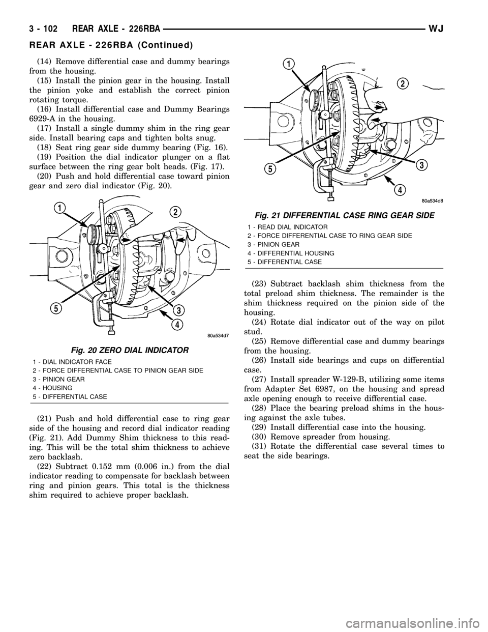
(20) Push and hold differential case toward pinion
gear and zero dial indicator (Fig. 20).
(21) Push and hold differential case to ring gear
side of the housing and record dial indicator reading
(Fig. 21). Add Dummy Shim thickness to this read-
ing. This will be the total shim thickness to achieve
zero backlash.
(22) Subtract 0.152 mm (0.006 in.) from the dial
indicator reading to compensate for backlash between
ring and pinion gears. This total is the thickness
shim required to achieve proper backlash.(23) Subtract backlash shim thickness from the
total preload shim thickness. The remainder is the
shim thickness required on the pinion side of the
housing.
(24) Rotate dial indicator out of the way on pilot
stud.
(25) Remove differential case and dummy bearings
from the housing.
(26) Install side bearings and cups on differential
case.
(27) Install spreader W-129-B, utilizing some items
from Adapter Set 6987, on the housing and spread
axle opening enough to receive differential case.
(28) Place the bearing preload shims in the hous-
ing against the axle tubes.
(29) Install differential case into the housing.
(30) Remove spreader from housing.
(31) Rotate the differential case several times to
seat the side bearings.
Fig. 20 ZERO DIAL INDICATOR
1 - DIAL INDICATOR FACE
2 - FORCE DIFFERENTIAL CASE TO PINION GEAR SIDE
3 - PINION GEAR
4 - HOUSING
5 - DIFFERENTIAL CASE
Fig. 21 DIFFERENTIAL CASE RING GEAR SIDE
1 - READ DIAL INDICATOR
2 - FORCE DIFFERENTIAL CASE TO RING GEAR SIDE
3 - PINION GEAR
4 - DIFFERENTIAL HOUSING
5 - DIFFERENTIAL CASE
3 - 102 REAR AXLE - 226RBAWJ
REAR AXLE - 226RBA (Continued)
Page 148 of 2199
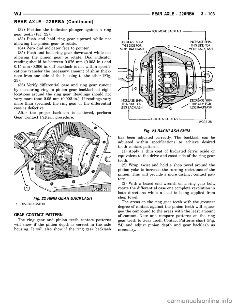
(32) Position the indicator plunger against a ring
gear tooth (Fig. 22).
(33) Push and hold ring gear upward while not
allowing the pinion gear to rotate.
(34) Zero dial indicator face to pointer.
(35) Push and hold ring gear downward while not
allowing the pinion gear to rotate. Dial indicator
reading should be between 0.076 mm (0.003 in.) and
0.15 mm (0.006 in.). If backlash is not within specifi-
cations transfer the necessary amount of shim thick-
ness from one side of the housing to the other (Fig.
23).
(36) Verify differential case and ring gear runout
by measuring ring to pinion gear backlash at eight
locations around the ring gear. Readings should not
vary more than 0.05 mm (0.002 in.). If readings vary
more than specified, the ring gear or the differential
case is defective.
After the proper backlash is achieved, perform
Gear Contact Pattern procedure.
GEAR CONTACT PATTERN
The ring gear and pinion teeth contact patterns
will show if the pinion depth is correct in the axle
housing. It will also show if the ring gear backlashhas been adjusted correctly. The backlash can be
adjusted within specifications to achieve desired
tooth contact patterns.
(1) Apply a thin coat of hydrated ferric oxide or
equivalent to the drive and coast side of the ring gear
teeth.
(2) Wrap, twist and hold a shop towel around the
pinion yoke to increase the turning resistance of the
pinion. This will provide a more distinct contact pat-
tern.
(3) With a boxed end wrench on a ring gear bolt,
rotate the differential case one complete revolution in
both directions while a load is being applied from
shop towel.
The areas on the ring gear teeth with the greatest
degree of contact against the pinion teeth will squee-
gee the compound to the areas with the least amount
of contact. Note and compare patterns on the ring
gear teeth to Gear Tooth Contact Patterns chart (Fig.
24) and adjust pinion depth and gear backlash as
necessary.
Fig. 22 RING GEAR BACKLASH
1 - DIAL INDICATOR
Fig. 23 BACKLASH SHIM
WJREAR AXLE - 226RBA 3 - 103
REAR AXLE - 226RBA (Continued)
Page 152 of 2199

Installer C-4308
Installer C-4340
Pilot Studs C-3288-B
Dial Indicator C-3339
Trac-lok Tool C-4487
Installer C-3972-A
Installer D-129
Remover D-103
Spreader
Installer 6448
WJREAR AXLE - 226RBA 3 - 107
REAR AXLE - 226RBA (Continued)
Page 161 of 2199

(9) Install a Pilot Stud C-3288-B at the left side of
the differential housing. Attach Dial Indicator C-3339
to pilot stud. Load the indicator plunger against the
opposite side of the housing (Fig. 47) and zero the
indicator.
CAUTION: Never spread the housing over 0.38 mm
(0.015 in). If housing is over-spread, it could dis-
torted and damaged the housing.
(10) Spread housing enough to remove the differ-
ential case from the housing. Measure the distance
with the dial indicator (Fig. 48).
(11) Remove the dial indicator.
(12) While holding the differential case in position,
remove the differential bearing cap bolts and caps.
(13) Remove differential from the housing and tag
differential bearing cups to indicate location (Fig. 49).
(14) Remove spreader from housing.
Fig. 47 DIAL INDICATOR LOCATION
1 - CLAMP
2 - DIAL INDICATOR
3 - LEVER ADAPTER
4 - SPREADER
5 - PILOT STUD
Fig. 48 SPREAD DIFFERENTIAL HOUSING
1 - DIAL INDICATOR
2 - SPREADER
Fig. 49 DIFFERENTIAL CASE REMOVAL
1 - DIFFERENTIAL HOUSING
2 - DIFFERENTIAL CASE
3 - BEARING CUPS
3 - 116 REAR AXLE - 226RBAWJ
DIFFERENTIAL (Continued)
Page 162 of 2199
DISASSEMBLY
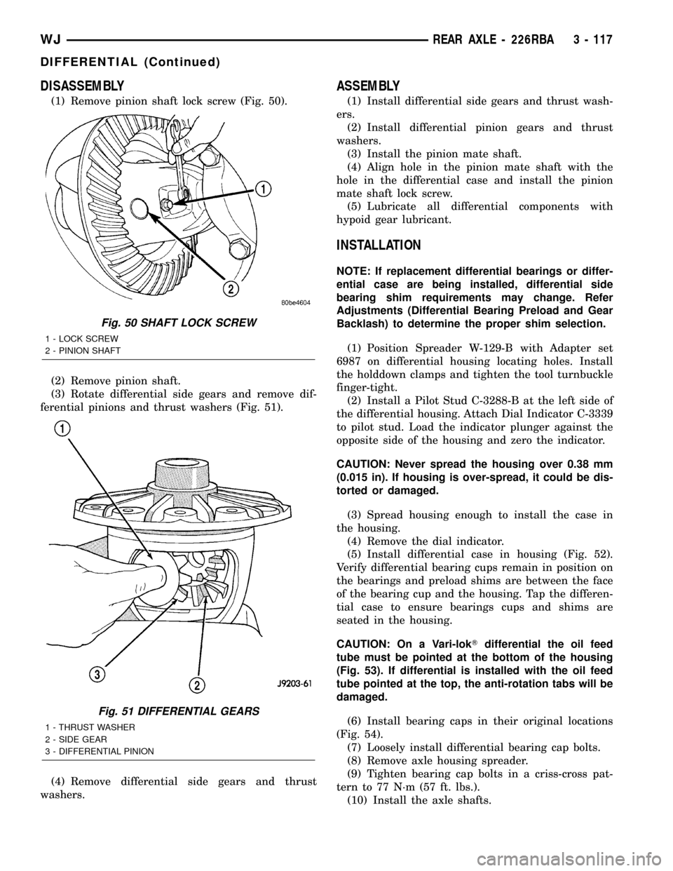
(1) Remove pinion shaft lock screw (Fig. 50).
(2) Remove pinion shaft.
(3) Rotate differential side gears and remove dif-
ferential pinions and thrust washers (Fig. 51).
(4) Remove differential side gears and thrust
washers.
ASSEMBLY
(1) Install differential side gears and thrust wash-
ers.
(2) Install differential pinion gears and thrust
washers.
(3) Install the pinion mate shaft.
(4) Align hole in the pinion mate shaft with the
hole in the differential case and install the pinion
mate shaft lock screw.
(5) Lubricate all differential components with
hypoid gear lubricant.
INSTALLATION
NOTE: If replacement differential bearings or differ-
ential case are being installed, differential side
bearing shim requirements may change. Refer
Adjustments (Differential Bearing Preload and Gear
Backlash) to determine the proper shim selection.
(1) Position Spreader W-129-B with Adapter set
6987 on differential housing locating holes. Install
the holddown clamps and tighten the tool turnbuckle
finger-tight.
(2) Install a Pilot Stud C-3288-B at the left side of
the differential housing. Attach Dial Indicator C-3339
to pilot stud. Load the indicator plunger against the
opposite side of the housing and zero the indicator.
CAUTION: Never spread the housing over 0.38 mm
(0.015 in). If housing is over-spread, it could be dis-
torted or damaged.
(3) Spread housing enough to install the case in
the housing.
(4) Remove the dial indicator.
(5) Install differential case in housing (Fig. 52).
Verify differential bearing cups remain in position on
the bearings and preload shims are between the face
of the bearing cup and the housing. Tap the differen-
tial case to ensure bearings cups and shims are
seated in the housing.
CAUTION: On a Vari-lokTdifferential the oil feed
tube must be pointed at the bottom of the housing
(Fig. 53). If differential is installed with the oil feed
tube pointed at the top, the anti-rotation tabs will be
damaged.
(6) Install bearing caps in their original locations
(Fig. 54).
(7) Loosely install differential bearing cap bolts.
(8) Remove axle housing spreader.
(9) Tighten bearing cap bolts in a criss-cross pat-
tern to 77 N´m (57 ft. lbs.).
(10) Install the axle shafts.
Fig. 50 SHAFT LOCK SCREW
1 - LOCK SCREW
2 - PINION SHAFT
Fig. 51 DIFFERENTIAL GEARS
1 - THRUST WASHER
2 - SIDE GEAR
3 - DIFFERENTIAL PINION
WJREAR AXLE - 226RBA 3 - 117
DIFFERENTIAL (Continued)
Page 176 of 2199
BRAKES
TABLE OF CONTENTS
page page
BRAKES - BASE........................... 1BRAKES - ABS........................... 41
BRAKES - BASE
TABLE OF CONTENTS
page page
BRAKES - BASE
DESCRIPTION..........................2
DIAGNOSIS AND TESTING - BASE BRAKE
SYSTEM.............................2
STANDARD PROCEDURE
STANDARD PROCEDURE - MANUAL
BLEEDING............................5
STANDARD PROCEDURE - PRESSURE
BLEEDING............................5
SPECIFICATIONS
BRAKE COMPONENTS..................6
TORQUE CHART......................6
SPECIAL TOOLS
BASE BRAKES........................7
BRAKE FLUID LEVEL SWITCH
REMOVAL.............................7
INSTALLATION..........................7
RED BRAKE WARN INDICATOR SWITCH
DESCRIPTION..........................7
OPERATION............................7
DIAGNOSIS AND TESTING - RED BRAKE
WARNING LAMP.......................7
ADJUSTABLE PEDAL SWITCH
REMOVAL.............................8
INSTALLATION..........................8
BRAKE LINES
DESCRIPTION..........................8
DIAGNOSIS AND TESTING - BRAKE HOSES
AND LINES...........................8
STANDARD PROCEDURE
STANDARD PROCEDURE - DOUBLE
INVERTED FLARING....................9
STANDARD PROCEDURE - ISO FLARING . . . 9
BRAKE PADS / SHOES
DESCRIPTION
DESCRIPTION - FRONT DISC BRAKE
SHOES.............................10DESCRIPTION - REAR DISC BRAKE SHOES . 10
OPERATION
OPERATION - FRONT DISC BRAKE SHOES . 10
OPERATION - REAR DISC BRAKE SHOES . . 10
REMOVAL
REMOVAL- FRONT DISC BRAKE SHOES . . . 11
REMOVAL - REAR DISC BRAKE SHOES....12
INSTALLATION
INSTALLATION - FRONT DISC BRAKE
SHOES.............................13
INSTALLATION - REAR DISC BRAKE
SHOES.............................14
DISC BRAKE CALIPERS
REMOVAL
REMOVAL - FRONT DISC BRAKE CALIPER . 14
REMOVAL - REAR DISC BRAKE CALIPER . . 15
DISASSEMBLY
DISASSEMBLY - FRONT DISC BRAKE
CALIPER............................17
DISASSEMBLY - REAR DISC BRAKE
CALIPER............................18
CLEANING - DISC BRAKE CALIPER.........19
INSPECTION - DISC BRAKE CALIPER.......19
ASSEMBLY
ASSEMBLY - FRONT DISC BRAKE CALIPER . 20
ASSEMBLY - REAR DISC BRAKE CALIPER . 21
INSTALLATION
INSTALLATION - FRONT DISC BRAKE
CALIPER............................22
INSTALLATION - REAR DISC BRAKE
CALIPER............................22
FLUID
DIAGNOSIS AND TESTING - BRAKE FLUID
CONTAMINATION.....................22
SPECIFICATIONS
BRAKE FLUID........................23
FLUID RESERVOIR
REMOVAL.............................23
WJBRAKES 5 - 1
Page 177 of 2199

INSTALLATION.........................23
MASTER CYLINDER
DESCRIPTION.........................23
OPERATION...........................24
DIAGNOSIS AND TESTING - MASTER
CYLINDER/POWER BOOSTER...........24
STANDARD PROCEDURE - MASTER
CYLINDER BLEEDING PROCEDURE......25
REMOVAL.............................25
INSTALLATION.........................25
PEDAL
DESCRIPTION
DESCRIPTION - STANDARD PEDAL.......25
DESCRIPTION - ADJUSTABLE PEDALS....25
OPERATION...........................26
REMOVAL
REMOVAL - NON-ADJUSTABLE PEDAL....26
REMOVAL - ADJUSTABLE PEDALS........27
INSTALLATION
INSTALLATION - NON-ADJUSTABLE PEDAL . 28
INSTALLATION - ADJUSTABLE PEDALS....28
PEDAL MOTOR
REMOVAL.............................28
INSTALLATION.........................28
POWER BRAKE BOOSTER
DESCRIPTION.........................29
OPERATION...........................29
REMOVAL.............................31
INSTALLATION.........................31
ROTORS
DIAGNOSIS AND TESTING
DIAGNOSIS AND TESTING - FRONT DISC
BRAKE ROTOR.......................31DIAGNOSIS AND TESTING - REAR DISC
BRAKE ROTOR.......................32
STANDARD PROCEDURE - DISC ROTOR
MACHINING..........................33
REMOVAL
REMOVAL - FRONT DISC BRAKE ROTOR . . 33
REMOVAL - REAR DISC BRAKE ROTOR . . . 33
INSTALLATION
INSTALLATION - FRONT DISC BRAKE
ROTOR .............................34
INSTALLATION - REAR DISC BRAKE
ROTOR .............................34
PARKING BRAKE
OPERATION...........................34
DIAGNOSIS AND TESTING - PARKING BRAKE . 34
CABLES
REMOVAL
REMOVAL - FRONT PARKING BRAKE
CABLE..............................35
REMOVAL - REAR PARKING BRAKE
CABLES............................36
INSTALLATION
INSTALLATION - FRONT PARKING BRAKE
CABLE..............................37
INSTALLATION - REAR PARKING BRAKE
CABLES............................37
LEVER
REMOVAL.............................38
INSTALLATION.........................39
SHOES
REMOVAL.............................39
INSTALLATION.........................39
ADJUSTMENTS - PARKING BRAKE SHOE....40
BRAKES - BASE
DESCRIPTION
Dual piston disc brake calipers are used on the
front. Single piston disc brake calipers are used on
the rear. Ventilated disc brake rotors are used on the
front and solid rotors are used on the rear.
Power brake assist is supplied by a vacuum oper-
ated, dual diaphragm power brake booster. The mas-
ter cylinder used for all applications has an
aluminum body and nylon reservoir with single filler
cap. A fluid level indicator is mounted to the side of
the reservoir.
The braking force of the rear wheels is controlled
by electronic brake distribution (EBD). The EBD
functions like a rear proportioning valve. The EBD
system uses the ABS system to control the slip of the
rear wheels in partial braking range. The braking
force of the rear wheels is controlled electronically by
using the inlet and outlet valves located in the HCU.
Factory installed brake linings on all models con-
sists of organic base material combined with metallic
particles.
DIAGNOSIS AND TESTING - BASE BRAKE
SYSTEM
Base brake components consist of the brake shoes,
calipers, rear park brake drums/rotors, front brake
rotors, brake lines, master cylinder, booster, HCU
and parking brake shoes.
Brake diagnosis involves determining if the prob-
lem is related to a mechanical, hydraulic, electrical
or vacuum operated component.
The first diagnosis step is the preliminary check.
PRELIMINARY BRAKE CHECK
(1) Check condition of tires and wheels. Damaged
wheels and worn, damaged, or underinflated tires
can cause pull, shudder, vibration, and a condition
similar to grab.
5 - 2 BRAKES - BASEWJ
Page 180 of 2199
NOTE: The front outer brake shoes are equipped
with a wear indicator. The indicator will produce an
audible noise when it contacts the rotor surface.
BRAKE CHATTER
Brake chatter is usually caused by loose or worn
components, or glazed/burnt lining. Rotors with hard
spots can also contribute to chatter. Additional causes
of chatter are out-of-tolerance rotors, brake lining not
securely attached to the shoes, loose wheel bearings
and contaminated brake lining.
THUMP/CLUNK NOISE
Thumping or clunk noises during braking are fre-
quentlynotcaused by brake components. In many
cases, such noises are caused by loose or damaged
steering, suspension, or engine components.
STANDARD PROCEDURE
STANDARD PROCEDURE - MANUAL BLEEDING
Use Mopar brake fluid, or an equivalent quality
fluid meeting SAE J1703-F and DOT 3 standards
only. Use fresh, clean fluid from a sealed container at
all times.
Do not pump the brake pedal at any time while
bleeding. Air in the system will be compressed into
small bubbles that are distributed throughout the
hydraulic system. This will make additional bleeding
operations necessary.
Do not allow the master cylinder to run out of fluid
during bleed operations. An empty cylinder will allow
additional air to be drawn into the system. Check the
cylinder fluid level frequently and add fluid as
needed.
Bleed only one brake component at a time in the
following sequence:
(1) Fill the master cylinder reservoir with brake
fluid.
(2) If calipers are overhauled, open all caliper
bleed screws. Then close each bleed screw as fluid
starts to drip from it. Top off master cylinder reser-
voir once more before proceeding.
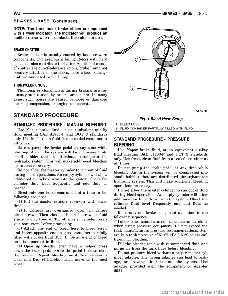
(3) Attach one end of bleed hose to bleed screw
and insert opposite end in glass container partially
filled with brake fluid (Fig. 1). Be sure end of bleed
hose is immersed in fluid.
(4) Open up bleeder, then have a helper press
down the brake pedal. Once the pedal is down close
the bleeder. Repeat bleeding until fluid stream is
clear and free of bubbles. Then move to the next
wheel.
STANDARD PROCEDURE - PRESSURE
BLEEDING
Use Mopar brake fluid, or an equivalent quality
fluid meeting SAE J1703-F and DOT 3 standards
only. Use fresh, clean fluid from a sealed container at
all times.
Do not pump the brake pedal at any time while
bleeding. Air in the system will be compressed into
small bubbles that are distributed throughout the
hydraulic system. This will make additional bleeding
operations necessary.
Do not allow the master cylinder to run out of fluid
during bleed operations. An empty cylinder will allow
additional air to be drawn into the system. Check the
cylinder fluid level frequently and add fluid as
needed.
Bleed only one brake component at a time in the
following sequence:
Follow the manufacturers instructions carefully
when using pressure equipment. Do not exceed the
tank manufacturers pressure recommendations. Gen-
erally, a tank pressure of 51-67 kPa (15-20 psi) is suf-
ficient for bleeding.
Fill the bleeder tank with recommended fluid and
purge air from the tank lines before bleeding.
Do not pressure bleed without a proper master cyl-
inder adapter. The wrong adapter can lead to leak-
age, or drawing air back into the system. Use
adapter provided with the equipment or Adapter
6921.
Fig. 1 Bleed Hose Setup
1 - BLEED HOSE
2 - FLUID CONTAINER PARTIALLY FILLED WITH FLUID
WJBRAKES - BASE 5 - 5
BRAKES - BASE (Continued)