Page 1203 of 2199
Fig. 11 4.0 LITER ENGINE RIGHT REAR RHD
8W - 91 - 28 8W-91 CONNECTOR/GROUND/SPLICE LOCATIONWJ
CONNECTOR/GROUND/SPLICE LOCATION (Continued)
Page 1204 of 2199
Fig. 12 TRANSMISSION 4.0 LITER ENGINE
WJ8W-91 CONNECTOR/GROUND/SPLICE LOCATION 8W - 91 - 29
CONNECTOR/GROUND/SPLICE LOCATION (Continued)
Page 1205 of 2199
Fig. 13 4.7 LITER ENGINE LEFT FRONT
8W - 91 - 30 8W-91 CONNECTOR/GROUND/SPLICE LOCATIONWJ
CONNECTOR/GROUND/SPLICE LOCATION (Continued)
Page 1206 of 2199
Fig. 14 4.7 LITER ENGINE RIGHT FRONT LHD
WJ8W-91 CONNECTOR/GROUND/SPLICE LOCATION 8W - 91 - 31
CONNECTOR/GROUND/SPLICE LOCATION (Continued)
Page 1207 of 2199
Fig. 15 4.7 LITER ENGINERIGHT FRONT RHD
8W - 91 - 32 8W-91 CONNECTOR/GROUND/SPLICE LOCATIONWJ
CONNECTOR/GROUND/SPLICE LOCATION (Continued)
Page 1208 of 2199
Fig. 16 TRANSMISSION 4.7 LITER ENGINE LEFT SIDE
Fig. 17 TRANSMISSION 4.7 LITER ENGINE RIGHT SIDE
WJ8W-91 CONNECTOR/GROUND/SPLICE LOCATION 8W - 91 - 33
CONNECTOR/GROUND/SPLICE LOCATION (Continued)
Page 1209 of 2199
Fig. 18 REAR ENGINE COMPARTMENT LHD
8W - 91 - 34 8W-91 CONNECTOR/GROUND/SPLICE LOCATIONWJ
CONNECTOR/GROUND/SPLICE LOCATION (Continued)
Page 1232 of 2199

(5) Reconnect the right and left body wire harness
bulkhead connectors to the connector receptacles
located near the center of the JB.
(6) Install and tighten the screws that secure the
right and left body wire harness bulkhead connectors
to the connector receptacles located near the center
of the JB. Tighten the screws to 2.2 N´m (20 in. lbs.).
(7) Reconnect the fused B(+) and the IOD wire
harness connectors to the connector receptacles
located near the bottom of the JB.
(8) Reach behind the JB to reconnect the instru-
ment panel wire harness bulkhead connector to the
connector receptacle located near the top of the JB.
(9) Install and tighten the screw that secures the
instrument panel wire harness bulkhead connector to
the connector receptacle located near the top of the
JB. Tighten the screw to 2.2 N´m (20 in. lbs.).
(10)
Reach behind the JB to reconnect the two
instrument panel wire harness connectors to the BCM
connector receptacles located near the bottom of the JB.
(11) Install the steering column opening cover onto
the instrument panel. Refer toSteering Column
Opening Coverin Body for the location of the steer-
ing column opening cover installation procedures.
(12)
Install the fuse cover onto the bottom of the JB.
(13) Reconnect the battery negative cable.
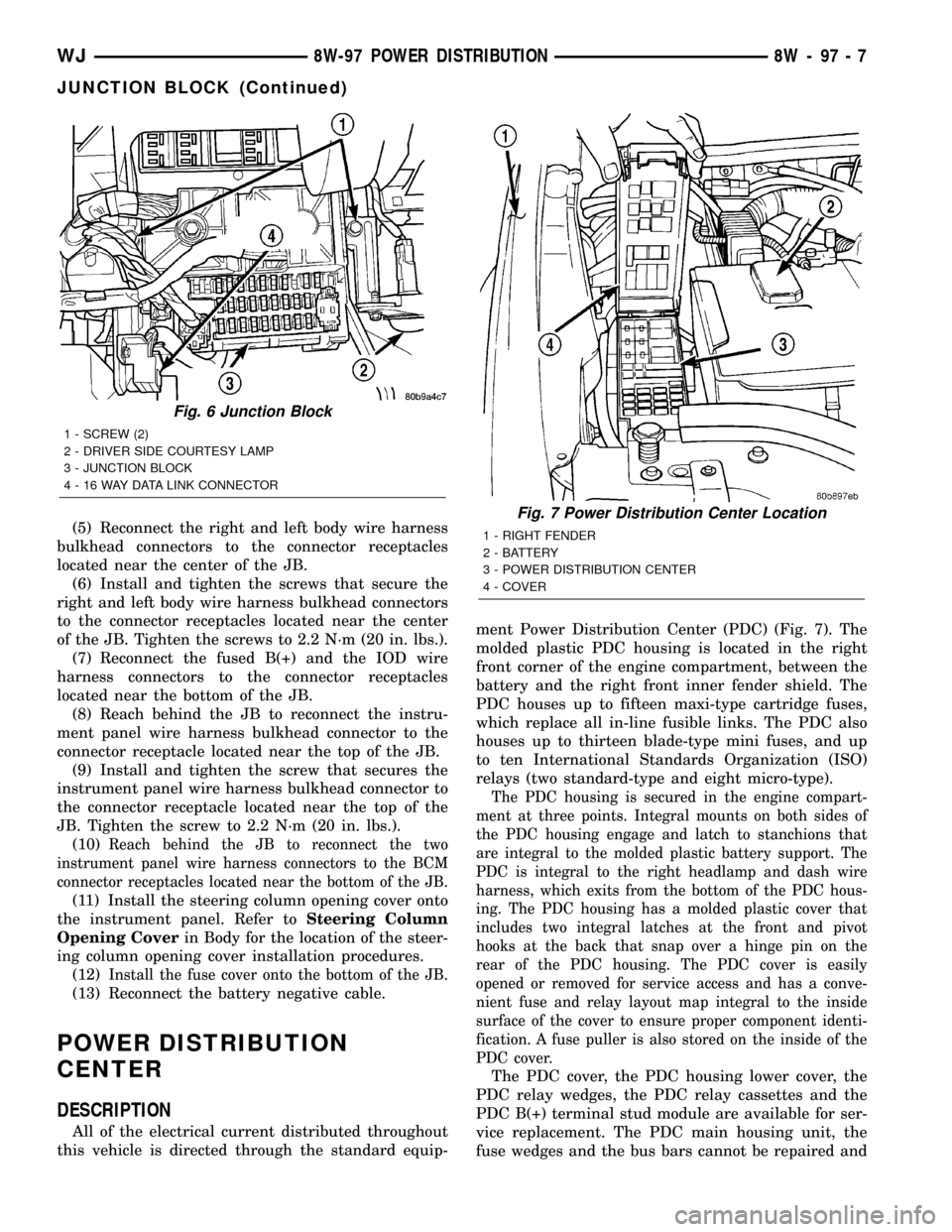
POWER DISTRIBUTION
CENTER
DESCRIPTION
All of the electrical current distributed throughout
this vehicle is directed through the standard equip-ment Power Distribution Center (PDC) (Fig. 7). The
molded plastic PDC housing is located in the right
front corner of the engine compartment, between the
battery and the right front inner fender shield. The
PDC houses up to fifteen maxi-type cartridge fuses,
which replace all in-line fusible links. The PDC also
houses up to thirteen blade-type mini fuses, and up
to ten International Standards Organization (ISO)
relays (two standard-type and eight micro-type).
The PDC housing is secured in the engine compart-
ment at three points. Integral mounts on both sides of
the PDC housing engage and latch to stanchions that
are integral to the molded plastic battery support. The
PDC is integral to the right headlamp and dash wire
harness, which exits from the bottom of the PDC hous-
ing. The PDC housing has a molded plastic cover that
includes two integral latches at the front and pivot
hooks at the back that snap over a hinge pin on the
rear of the PDC housing. The PDC cover is easily
opened or removed for service access and has a conve-
nient fuse and relay layout map integral to the inside
surface of the cover to ensure proper component identi-
fication. A fuse puller is also stored on the inside of the
PDC cover.
The PDC cover, the PDC housing lower cover, the
PDC relay wedges, the PDC relay cassettes and the
PDC B(+) terminal stud module are available for ser-
vice replacement. The PDC main housing unit, the
fuse wedges and the bus bars cannot be repaired and
Fig. 6 Junction Block
1 - SCREW (2)
2 - DRIVER SIDE COURTESY LAMP
3 - JUNCTION BLOCK
4 - 16 WAY DATA LINK CONNECTOR
Fig. 7 Power Distribution Center Location
1 - RIGHT FENDER
2 - BATTERY
3 - POWER DISTRIBUTION CENTER
4 - COVER
WJ8W-97 POWER DISTRIBUTION 8W - 97 - 7
JUNCTION BLOCK (Continued)