2002 JEEP GRAND CHEROKEE hood open
[x] Cancel search: hood openPage 618 of 2199

Washer hose is available for service only as roll
stock, which must then be cut to length. The molded
plastic washer hose fittings cannot be repaired. If
these fittings are faulty or damaged, they must be
replaced.
OPERATION
Washer fluid in the washer reservoir is pressurized
and fed by the front washer pump/motor through the
front washer system plumbing and fittings to the two
front washer nozzles. Whenever routing the washer
hose or a wire harness containing a washer hose, it
must be routed away from hot, sharp, or moving
parts; and, sharp bends that might pinch the hose
must be avoided.
FRONT WASHER NOZZLE
DESCRIPTION
The two front washer nozzles have integral snap
features that secure them in dedicated holes in the
cowl plenum cover/grille panel located near the base
of the windshield. The domed upper surface of the
washer nozzle is visible on the top of the plenum cov-
er/grille panel, and the nozzle orifice is oriented
towards the windshield glass. The washer plumbing
fittings for the washer nozzles are concealed beneath
the cowl plenum cover/grille panel. These fluidic
washer nozzles are constructed of molded plastic. The
cowl plenum cover/grille panel must be removed from
the vehicle to access the nozzles for service. The
washer nozzles cannot be adjusted or repaired. If
faulty or damaged, they must be replaced.
OPERATION
The two front washer nozzles are designed to dis-
pense washer fluid into the wiper pattern area on the
outside of the windshield glass. Pressurized washer
fluid is fed to each nozzle from the washer reservoir
by the front washer pump/motor through a single
hose, which is attached to a barbed nipple on each
front washer nozzle below the cowl plenum cover/
grille panel. The washer nozzles incorporate a fluidic
design, which causes the nozzle to emit the pressur-
ized washer fluid as an oscillating stream to more
effectively cover a larger area of the glass area to be
cleaned.
REMOVAL
(1) Disconnect and isolate the battery negative
cable.
(2) Remove the wiper arms from the wiper pivots.
(Refer to 8 - ELECTRICAL/FRONT WIPERS/WASH-
ERS/FRONT WIPER ARMS - REMOVAL).
(3) Unlatch and open the hood.(4) Pull the hood to plenum seal off of the forward
flanges of the cowl grille cover and the plenum panel.
(5) Remove the six plastic nuts (2 short and 4
long) that secure the cowl grille cover to the studs on
the cowl top panel near the base of the windshield
(Fig. 4).
(6) Lift the left end of the cowl grille cover off of
the cowl plenum panel far enough to access the front
washer plumbing.
(7) Disconnect the engine compartment washer
hose from the cowl grille cover washer hose at the
plastic elbow connector.
(8) Remove the cowl grille cover from the cowl ple-
num and cowl top panels through the opening
between the hood and the base of the windshield.
(9) From the underside of the cowl grille cover, dis-
connect the washer hose(s) from the barbed nipple(s)
of the front washer nozzle(s).
(10) From the underside of the cowl grille cover,
release the integral snap features of the front washer
nozzle(s) and push the nozzle(s) out through the
mounting hole toward the top side of the cowl grille
cover.
INSTALLATION
(1) From the top side of the cowl grille cover,
insert the nipple end of the front washer nozzle(s)
through the mounting hole in the cowl grille cover.
(2) Push firmly and evenly on the top of the front
washer nozzle until the integral snap features lock
into place on the underside of the cowl grille cover.
(3) From the underside of the cowl grille cover,
reconnect the washer hose(s) to the barbed nipple(s)
of the front washer nozzle(s).
Fig. 4 Cowl Grille Cover Remove/Install
1 - WASHER HOSE CONNECTION
2 - STUDS (6)
3 - COWL GRILLE COVER
4 - PLASTIC NUT (6)
WJFRONT WIPERS/WASHERS 8R - 11
FRONT WASHER HOSES/TUBES (Continued)
Page 619 of 2199
(4) Reinstall the washer hoses for the front washer
nozzle(s) into their routing clips on the underside of
the cowl grille cover.
(5) Position the cowl grille cover onto the cowl ple-
num and cowl top panels through the opening
between the hood and the base of the windshield
(Fig. 4).
(6) Lift the left end of the cowl grille cover off of
the cowl plenum panel far enough to access the front
washer plumbing.
(7) Reconnect the cowl grille cover washer hose to
the engine compartment washer hose at the elbow
connector.
(8) Install the six plastic nuts that secure the cowl
grille cover to the studs on the cowl top panel near
the base of the windshield. These nuts are to be
installed by pushing them onto the studs in the fol-
lowing sequence:
(a) First, install the short nuts to the third stud
from the right, then the second stud from the left.
(b) Next, install the long nuts to the right out-
board stud, then the left outboard stud.
(c) Finally, install the two remaining long nuts
to the third stud from the left, then the second
stud from the right.
(9) Starting at the ends and working toward the
center, push the hood to plenum seal onto the for-
ward flanges of the cowl grille cover and the plenum
panel.
(10) Close and latch the hood.
(11) Reinstall the wiper arms onto the wiper piv-
ots. (Refer to 8 - ELECTRICAL/FRONT WIPERS/
WASHERS/FRONT WIPER ARMS -
INSTALLATION).
(12) Reconnect the battery negative cable.
FRONT WASHER PUMP/
MOTOR
DESCRIPTION
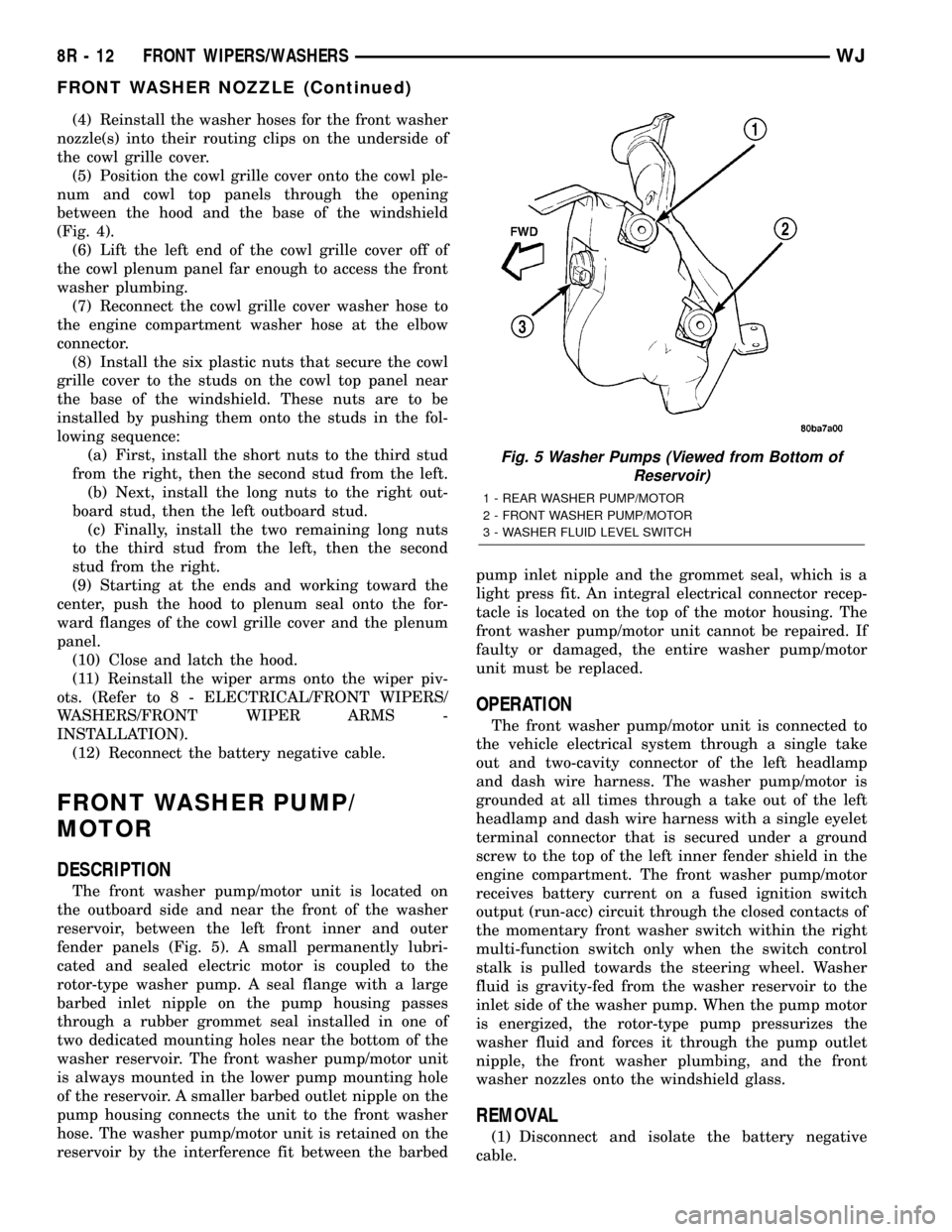
The front washer pump/motor unit is located on
the outboard side and near the front of the washer
reservoir, between the left front inner and outer
fender panels (Fig. 5). A small permanently lubri-
cated and sealed electric motor is coupled to the
rotor-type washer pump. A seal flange with a large
barbed inlet nipple on the pump housing passes
through a rubber grommet seal installed in one of
two dedicated mounting holes near the bottom of the
washer reservoir. The front washer pump/motor unit
is always mounted in the lower pump mounting hole
of the reservoir. A smaller barbed outlet nipple on the
pump housing connects the unit to the front washer
hose. The washer pump/motor unit is retained on the
reservoir by the interference fit between the barbedpump inlet nipple and the grommet seal, which is a
light press fit. An integral electrical connector recep-
tacle is located on the top of the motor housing. The
front washer pump/motor unit cannot be repaired. If
faulty or damaged, the entire washer pump/motor
unit must be replaced.
OPERATION
The front washer pump/motor unit is connected to
the vehicle electrical system through a single take
out and two-cavity connector of the left headlamp
and dash wire harness. The washer pump/motor is
grounded at all times through a take out of the left
headlamp and dash wire harness with a single eyelet
terminal connector that is secured under a ground
screw to the top of the left inner fender shield in the
engine compartment. The front washer pump/motor
receives battery current on a fused ignition switch
output (run-acc) circuit through the closed contacts of
the momentary front washer switch within the right
multi-function switch only when the switch control
stalk is pulled towards the steering wheel. Washer
fluid is gravity-fed from the washer reservoir to the
inlet side of the washer pump. When the pump motor
is energized, the rotor-type pump pressurizes the
washer fluid and forces it through the pump outlet
nipple, the front washer plumbing, and the front
washer nozzles onto the windshield glass.
REMOVAL
(1) Disconnect and isolate the battery negative
cable.
Fig. 5 Washer Pumps (Viewed from Bottom of
Reservoir)
1 - REAR WASHER PUMP/MOTOR
2 - FRONT WASHER PUMP/MOTOR
3 - WASHER FLUID LEVEL SWITCH
8R - 12 FRONT WIPERS/WASHERSWJ
FRONT WASHER NOZZLE (Continued)
Page 624 of 2199

crank arm, the two wiper linkage members, and the
two wiper pivots mechanically convert the rotary out-
put of the wiper motor to the back and forth wiping
motion of the wiper arms and blades on the glass.
REMOVAL
(1) Disconnect and isolate the battery negative
cable.
(2) Remove the front wiper arms from the wiper
pivots. (Refer to 8 - ELECTRICAL/FRONT WIPERS/
WASHERS/FRONT WIPER ARMS - REMOVAL).
(3) Unlatch and open the hood.
(4) Remove the hood to plenum seal from the for-
ward flanges of the cowl grille cover and the plenum
panel.
(5) Remove the six plastic nuts (2 short and 4
long) that secure the cowl grille cover to the studs on
the cowl top panel near the base of the windshield
(Fig. 12).
(6) Lift the left end of the cowl grille cover off of
the cowl plenum panel far enough to access the front
washer plumbing.
(7) Disconnect the front washer engine compart-
ment hose from the cowl grille cover hose at the
elbow connector.
(8) Remove the cowl grille cover from the cowl ple-
num and cowl top panels through the opening
between the hood and the base of the windshield.
(9) Remove the four screws that secure the front
wiper module to the cowl plenum panel (Fig. 13).
(10) Lift the left end of the front wiper module far
enough to access the front wiper motor wire harness
connector.(11) Disconnect the left headlamp and dash wire
harness connector for the front wiper motor from the
front wiper motor pigtail wire connector.
(12) Remove the front wiper module from the cowl
plenum as a unit.
INSTALLATION
(1) Position the front wiper module into the cowl
plenum as a unit (Fig. 13).
(2) Lift the left end of the front wiper module far
enough to access the front wiper motor wire harness
connector.
(3) Reconnect the left headlamp and dash wire
harness connector for the front wiper motor to the
front wiper motor pigtail wire connector.
(4) Loosely install one of the front wiper module
mounting screws to the mounting hole near the pivot
on the right end of the module to locate the module
in the plenum.
(5) Working from left to right, install and tighten
the four screws that secure the front wiper module to
the cowl plenum panel. Tighten the screws to 8 N´m
(72 in. lbs.).
(6) Position the cowl grille cover onto the cowl ple-
num and cowl top panels through the opening
between the hood and the base of the windshield
(Fig. 12).
(7) Lift the left end of the cowl grille cover off of
the cowl plenum panel far enough to access the front
washer plumbing.
(8) Reconnect the front washer system engine com-
partment hose to the cowl grille cover hose at the
elbow connector.
Fig. 12 Cowl Grille Cover Remove/Install
1 - WASHER HOSE CONNECTION
2 - STUDS (6)
3 - COWL GRILLE COVER
4 - PLASTIC NUT (6)
Fig. 13 Front Wiper Module Remove/Install
1 - FRONT WIPER MODULE
2 - SCREW (4)
3 - WIRE HARNESS CONNECTOR
4 - LOWER COWL PLENUM PANEL
WJFRONT WIPERS/WASHERS 8R - 17
FRONT WIPER MODULE (Continued)
Page 625 of 2199

(9) Install the six plastic nuts that secure the cowl
grille cover to the studs on the cowl top panel near
the base of the windshield. These nuts are to be
installed by pushing them onto the studs in the fol-
lowing sequence:
(a) First, install the short nuts to the third stud
from the right, then the second stud from the left.
(b) Next, install long nuts to the right outboard
stud, then the left outboard stud.
(c) Finally, install the two remaining long nuts
to the third stud from the left, then the second
stud from the right.
(10) Starting at the ends and working toward the
center, push the hood to plenum seal onto the for-
ward flanges of the cowl grille cover and the plenum
panel.
(11) Close and latch the hood.
(12) Reinstall the wiper arms onto the wiper piv-
ots. (Refer to 8 - ELECTRICAL/FRONT WIPERS/
WASHERS/FRONT WIPER ARMS -
INSTALLATION).
(13) Reconnect the battery negative cable.
RAIN SENSOR MODULE
DESCRIPTION
The Rain Sensor Module (RSM) is the primary
component of the automatic wiper system (Fig. 14).
The RSM is located on the inside of the windshield,
between the rear view mirror mounting button and
the windshield header and is concealed behind a
molded plastic trim cover that snaps over the modulehousing. The triangular-shaped molded black plastic
housing of the RSM has a rectangular opening
located on the upper end of the housing for the mod-
ule connector receptacle, which contains four termi-
nal pins. These terminal pins connect the rain sensor
to the vehicle electrical system through a dedicated
take out and connector of the overhead wire harness
that extends from above the headliner. Five openings
on the windshield side of the RSM housing are fitted
with eight convex clear plastic lenses. A metal spring
clip on each side of the housing near the bottom
secures the RSM to a plastic mounting bracket that
is bonded to the windshield glass. Concealed within
the RSM housing is the electronic circuitry of the
module, which includes four InfraRed (IR) diodes,
two photocells, and a microprocessor.
The RSM software is Flash compatible, which
means it can be reprogrammed using Flash repro-
gramming procedures. However, if any of the hard-
ware of the RSM is damaged or faulty, the entire
module must be replaced. The RSM bracket is ser-
viced as a unit with the windshield glass. If the
bracket is faulty, damaged, or separated from the
windshield glass, the windshield unit must be
replaced.
OPERATION
The microprocessor-based Rain Sensor Module
(RSM) senses moisture in the wipe pattern on the
outside of the windshield glass and sends wipe com-
mands to the Body Control Module (BCM). Four
InfraRed (IR) diodes within the RSM generate IR
light beams that are aimed by four of the convex
optical lenses near the base of the module through
the windshield glass. Four additional convex optical
lenses near the top of the RSM are focused on the IR
light beams on the outside of the windshield glass
and allow the two photocells within the module to
sense changes in the intensity of these IR light
beams. When sufficient moisture accumulates within
the wipe pattern of the windshield glass, the RSM
detects a change in the monitored IR light beam
intensity.
The internal programming of the RSM then sends
the appropriate electronic wipe command messages
to the BCM over the Programmable Communications
Interface (PCI) data bus. The BCM responds by acti-
vating or deactivating the front wiper system. The
BCM also sends electronic sensitivity level messages
to the RSM over the PCI data bus based upon the
driver-selected sensitivity setting of the control knob
on the control stalk of the right (wiper) multi-func-
tion switch. The higher the selected sensitivity set-
ting the more sensitive the RSM is to the
accumulated moisture on the windshield glass, and
Fig. 14 Rain Sensor Module
1 - SPRING CLIP (2)
2 - INFRARED LENS (4)
3 - HOUSING
4 - CONNECTOR RECEPTACLE
5 - PHOTOCELL LENS (4)
8R - 18 FRONT WIPERS/WASHERSWJ
FRONT WIPER MODULE (Continued)
Page 1181 of 2199
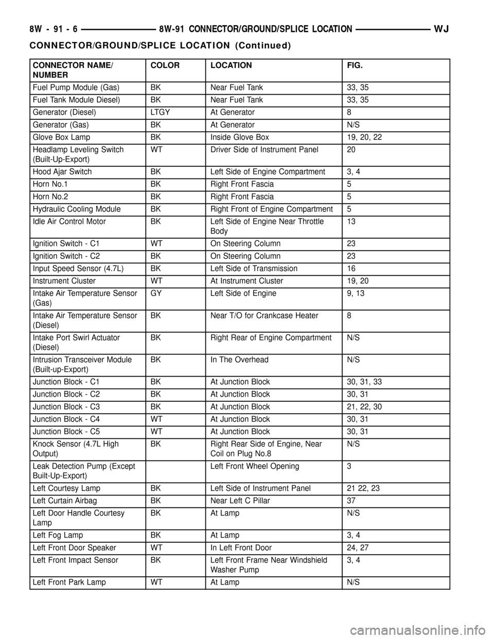
CONNECTOR NAME/
NUMBERCOLOR LOCATION FIG.
Fuel Pump Module (Gas) BK Near Fuel Tank 33, 35
Fuel Tank Module Diesel) BK Near Fuel Tank 33, 35
Generator (Diesel) LTGY At Generator 8
Generator (Gas) BK At Generator N/S
Glove Box Lamp BK Inside Glove Box 19, 20, 22
Headlamp Leveling Switch
(Built-Up-Export)WT Driver Side of Instrument Panel 20
Hood Ajar Switch BK Left Side of Engine Compartment 3, 4
Horn No.1 BK Right Front Fascia 5
Horn No.2 BK Right Front Fascia 5
Hydraulic Cooling Module BK Right Front of Engine Compartment 5
Idle Air Control Motor BK Left Side of Engine Near Throttle
Body13
Ignition Switch - C1 WT On Steering Column 23
Ignition Switch - C2 BK On Steering Column 23
Input Speed Sensor (4.7L) BK Left Side of Transmission 16
Instrument Cluster WT At Instrument Cluster 19, 20
Intake Air Temperature Sensor
(Gas)GY Left Side of Engine 9, 13
Intake Air Temperature Sensor
(Diesel)BK Near T/O for Crankcase Heater 8
Intake Port Swirl Actuator
(Diesel)BK Right Rear of Engine Compartment N/S
Intrusion Transceiver Module
(Built-up-Export)BK In The Overhead N/S
Junction Block - C1 BK At Junction Block 30, 31, 33
Junction Block - C2 BK At Junction Block 30, 31
Junction Block - C3 BK At Junction Block 21, 22, 30
Junction Block - C4 WT At Junction Block 30, 31
Junction Block - C5 WT At Junction Block 30, 31
Knock Sensor (4.7L High
Output)BK Right Rear Side of Engine, Near
Coil on Plug No.8N/S
Leak Detection Pump (Except
Built-Up-Export)Left Front Wheel Opening 3
Left Courtesy Lamp BK Left Side of Instrument Panel 21 22, 23
Left Curtain Airbag BK Near Left C Pillar 37
Left Door Handle Courtesy
LampBK At Lamp N/S
Left Fog Lamp BK At Lamp 3, 4
Left Front Door Speaker WT In Left Front Door 24, 27
Left Front Impact Sensor BK Left Front Frame Near Windshield
Washer Pump3, 4
Left Front Park Lamp WT At Lamp N/S
8W - 91 - 6 8W-91 CONNECTOR/GROUND/SPLICE LOCATIONWJ
CONNECTOR/GROUND/SPLICE LOCATION (Continued)
Page 1874 of 2199
BODY
TABLE OF CONTENTS
page page
BODY
DIAGNOSIS AND TESTING
WATER LEAKS........................1
WIND NOISE..........................2
STANDARD PROCEDURE
STANDARD PROCEDURE - BODY
LUBRICATION.........................2
STANDARD PROCEDURE - DRILLING AND
WELDING............................3
SPECIFICATIONS
BODY LUBRICANTS....................3
SPECIFICATIONS - TORQUE.............4
SPECIAL TOOLS
BODY...............................4DECKLID/HATCH/LIFTGATE/TAILGATE........5
DOOR - FRONT.........................11
DOORS - REAR.........................19
EXTERIOR.............................25
HOOD.................................33
INSTRUMENT PANEL SYSTEM.............36
INTERIOR..............................69
PAINT.................................81
SEATS................................83
STATIONARY GLASS.....................93
SUNROOF.............................96
WEATHERSTRIP/SEALS..................105
BODY STRUCTURE.....................112
BODY
DIAGNOSIS AND TESTING
WATER LEAKS
Water leaks can be caused by poor sealing,
improper body component alignment, body seam
porosity, missing plugs, or blocked drain holes. Cen-
trifugal and gravitational force can cause water to
drip from a location away from the actual leak point,
making leak detection difficult. All body sealing
points should be water tight in normal wet-driving
conditions. Water flowing downward from the front of
the vehicle should not enter the passenger or luggage
compartment. Moving sealing surfaces will not
always seal water tight under all conditions. At
times, side glass or door seals will allow water to
enter the passenger compartment during high pres-
sure washing or hard driving rain (severe) condi-
tions. Overcompensating on door or glass
adjustments to stop a water leak that occurs under
severe conditions can cause premature seal wear and
excessive closing or latching effort. After completing
a repair, water test vehicle to verify leak has stopped
before returning vehicle to use.
VISUAL INSPECTION BEFORE WATER LEAK TESTS
Verify that floor and body plugs are in place, body
drains are clear, and body components are properly
aligned and sealed. If component alignment or seal-
ing is necessary, refer to the appropriate section of
this group for proper procedures.
WATER LEAK TESTS
WARNING: DO NOT USE ELECTRIC SHOP LIGHTS
OR TOOLS IN WATER TEST AREA. PERSONAL
INJURY CAN RESULT.
When the conditions causing a water leak have
been determined, simulate the conditions as closely
as possible.
²If a leak occurs with the vehicle parked in a
steady light rain, flood the leak area with an open-
ended garden hose.
²If a leak occurs while driving at highway speeds
in a steady rain, test the leak area with a reasonable
velocity stream or fan spray of water. Direct the
spray in a direction comparable to actual conditions.
²If a leak occurs when the vehicle is parked on an
incline, hoist the end or side of the vehicle to simu-
late this condition. This method can be used when
the leak occurs when the vehicle accelerates, stops or
turns. If the leak occurs on acceleration, hoist the
front of the vehicle. If the leak occurs when braking,
hoist the back of the vehicle. If the leak occurs on left
turns, hoist the left side of the vehicle. If the leak
occurs on right turns, hoist the right side of the vehi-
cle. For hoisting recommendations refer to Group 0,
Lubrication and Maintenance, General Information
section.
WATER LEAK DETECTION
To detect a water leak point-of-entry, do a water
test and watch for water tracks or droplets forming
on the inside of the vehicle. If necessary, remove inte-
rior trim covers or panels to gain visual access to the
WJBODY 23 - 1
Page 1901 of 2199
EXTERIOR NAME PLATES
REMOVAL
NOTE: Exterior nameplates are attached to body
panels with adhesive tape.
(1) Apply a length of masking tape on the body,
parallel to the top edge of the nameplate to use as a
guide, if necessary.
(2) If temperature is below 21ÉC (70ÉF) warm
emblem with a heat lamp or gun. Do not exceed 52ÉC
(120ÉF) when heating emblem.
(3) Insert a plastic trim stick or a hard wood
wedge behind the emblem to separate the adhesive
backing from the body.
(4) Clean adhesive residue from body with MOPAR
Super Clean solvent or equivalent.
INSTALLATION
(1) Remove protective cover from adhesive tape on
back of emblem.
(2) Position emblem properly on body.(3) Press emblem firmly to body with palm of
hand.
(4) If temperature is below 21ÉC (70ÉF) warm
emblem with a heat lamp or gun to assure adhesion.
Do not exceed 52ÉC (120ÉF) when heating emblem.
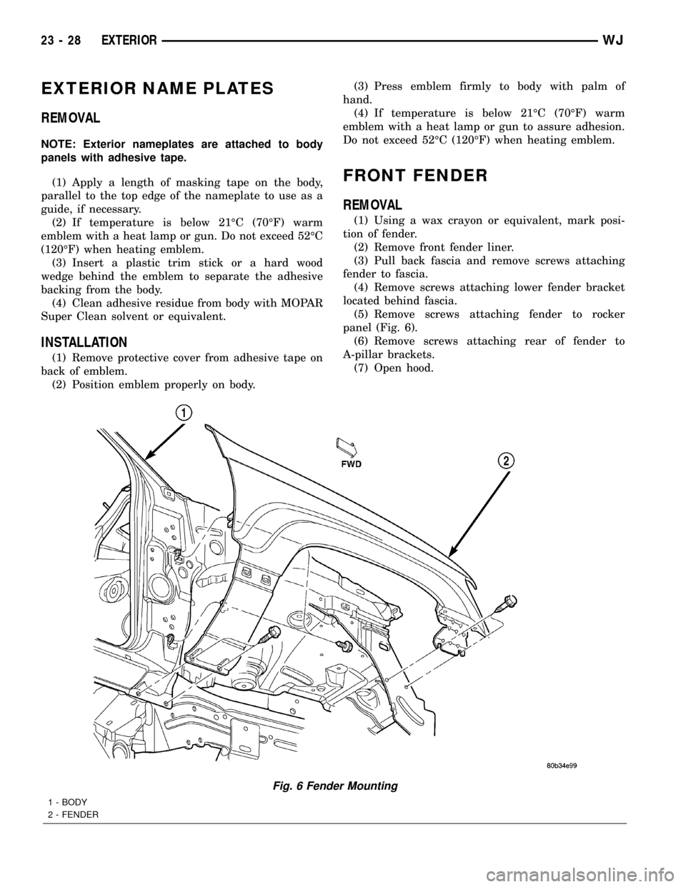
FRONT FENDER
REMOVAL
(1) Using a wax crayon or equivalent, mark posi-
tion of fender.
(2) Remove front fender liner.
(3) Pull back fascia and remove screws attaching
fender to fascia.
(4) Remove screws attaching lower fender bracket
located behind fascia.
(5) Remove screws attaching fender to rocker
panel (Fig. 6).
(6) Remove screws attaching rear of fender to
A-pillar brackets.
(7) Open hood.
Fig. 6 Fender Mounting
1 - BODY
2 - FENDER
23 - 28 EXTERIORWJ
Page 1902 of 2199
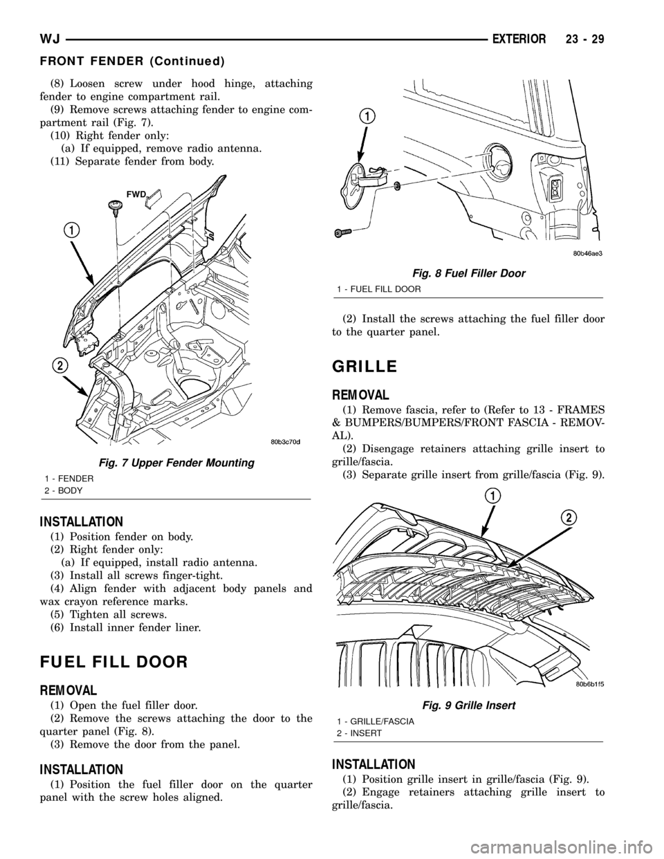
(8) Loosen screw under hood hinge, attaching
fender to engine compartment rail.
(9) Remove screws attaching fender to engine com-
partment rail (Fig. 7).
(10) Right fender only:
(a) If equipped, remove radio antenna.
(11) Separate fender from body.
INSTALLATION
(1) Position fender on body.
(2) Right fender only:
(a) If equipped, install radio antenna.
(3) Install all screws finger-tight.
(4) Align fender with adjacent body panels and
wax crayon reference marks.
(5) Tighten all screws.
(6) Install inner fender liner.
FUEL FILL DOOR
REMOVAL
(1) Open the fuel filler door.
(2) Remove the screws attaching the door to the
quarter panel (Fig. 8).
(3) Remove the door from the panel.
INSTALLATION
(1) Position the fuel filler door on the quarter
panel with the screw holes aligned.(2) Install the screws attaching the fuel filler door
to the quarter panel.
GRILLE
REMOVAL
(1) Remove fascia, refer to (Refer to 13 - FRAMES
& BUMPERS/BUMPERS/FRONT FASCIA - REMOV-
AL).
(2) Disengage retainers attaching grille insert to
grille/fascia.
(3) Separate grille insert from grille/fascia (Fig. 9).
INSTALLATION
(1) Position grille insert in grille/fascia (Fig. 9).
(2) Engage retainers attaching grille insert to
grille/fascia.
Fig. 7 Upper Fender Mounting
1 - FENDER
2 - BODY
Fig. 8 Fuel Filler Door
1 - FUEL FILL DOOR
Fig. 9 Grille Insert
1 - GRILLE/FASCIA
2 - INSERT
WJEXTERIOR 23 - 29
FRONT FENDER (Continued)