2002 JEEP GRAND CHEROKEE Gear
[x] Cancel search: GearPage 71 of 2199

(10) Push and hold differential case to pinion gear
side of the housing and zero dial indicator (Fig. 15).
(11) Push and hold differential case to ring gear
side of the housing and record dial indicator reading
(Fig. 16).(12) Add 0.152 mm (0.006 in.) to the zero end play
total. This new total represents the thickness of
shims to compress or preload the new bearings when
the differential is installed.
(13) Rotate dial indicator out of the way on the
pilot stud.
(14) Remove differential case and dummy bearings
from the housing.
(15) Install the pinion gear in the housing. Install
the pinion yoke and establish the correct pinion
rotating torque.
(16) Install differential case and Dummy Bearings
D-348 in the housing.
(17) Install a single dummy shim in the ring gear
side. Install bearing caps and tighten bolts snug.
(18) Seat ring gear side dummy bearing (Fig. 13).
(19) Position the dial indicator plunger on a flat
surface between the ring gear bolt heads (Fig. 14).
(20) Push and hold differential case toward pinion
gear and zero dial indicator (Fig. 17).
Fig. 15 ZERO DIAL INDICATOR
1 - FORCE DIFFERENTIAL CASE TO PINION GEAR SIDE
2 - PILOT STUD
3 - INDICATOR EXTENSION
4 - DIAL INDICATOR FACE
Fig. 16 RECORED DIAL INDICATOR READING
1 - DIAL INDICATOR
2 - DIFFERENTIAL CASE TO RING GEAR SIDE
3 - DIFFERENTIAL HOUSING
Fig. 17 ZERO DIAL INDICATOR
1 - DIAL INDICATOR
2 - FORCE DIFFERENTIAL CASE TO PINION GEAR SIDE
3 - PINION GEAR
4 - DIFFERENTIAL HOUSING
5 - DIFFERENTIAL CASE
3 - 26 FRONT AXLE - 186FBIWJ
FRONT AXLE - 186FBI (Continued)
Page 72 of 2199
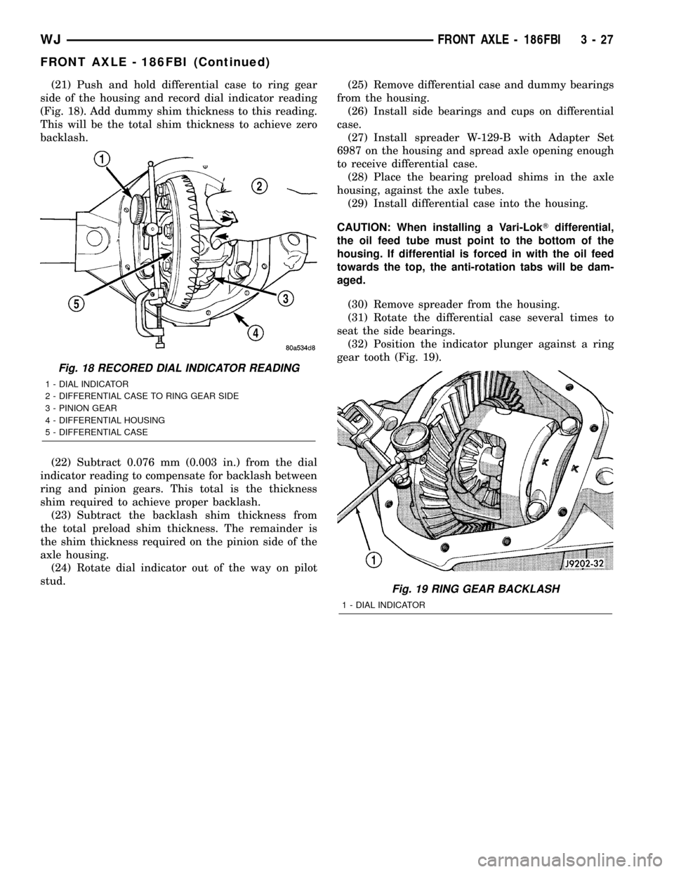
(21) Push and hold differential case to ring gear
side of the housing and record dial indicator reading
(Fig. 18). Add dummy shim thickness to this reading.
This will be the total shim thickness to achieve zero
backlash.
(22) Subtract 0.076 mm (0.003 in.) from the dial
indicator reading to compensate for backlash between
ring and pinion gears. This total is the thickness
shim required to achieve proper backlash.
(23) Subtract the backlash shim thickness from
the total preload shim thickness. The remainder is
the shim thickness required on the pinion side of the
axle housing.
(24) Rotate dial indicator out of the way on pilot
stud.(25) Remove differential case and dummy bearings
from the housing.
(26) Install side bearings and cups on differential
case.
(27) Install spreader W-129-B with Adapter Set
6987 on the housing and spread axle opening enough
to receive differential case.
(28) Place the bearing preload shims in the axle
housing, against the axle tubes.
(29) Install differential case into the housing.
CAUTION: When installing a Vari-LokTdifferential,
the oil feed tube must point to the bottom of the
housing. If differential is forced in with the oil feed
towards the top, the anti-rotation tabs will be dam-
aged.
(30) Remove spreader from the housing.
(31) Rotate the differential case several times to
seat the side bearings.
(32) Position the indicator plunger against a ring
gear tooth (Fig. 19).
Fig. 18 RECORED DIAL INDICATOR READING
1 - DIAL INDICATOR
2 - DIFFERENTIAL CASE TO RING GEAR SIDE
3 - PINION GEAR
4 - DIFFERENTIAL HOUSING
5 - DIFFERENTIAL CASE
Fig. 19 RING GEAR BACKLASH
1 - DIAL INDICATOR
WJFRONT AXLE - 186FBI 3 - 27
FRONT AXLE - 186FBI (Continued)
Page 73 of 2199
(33) Push and hold ring gear upward while not
allowing the pinion gear to rotate.
(34) Zero dial indicator face to pointer.
(35) Push and hold ring gear downward while not
allowing the pinion gear to rotate. Dial indicator
reading should be between 0.12 mm (0.005 in.) and
0.20 mm (0.008 in.). If backlash is not within specifi-
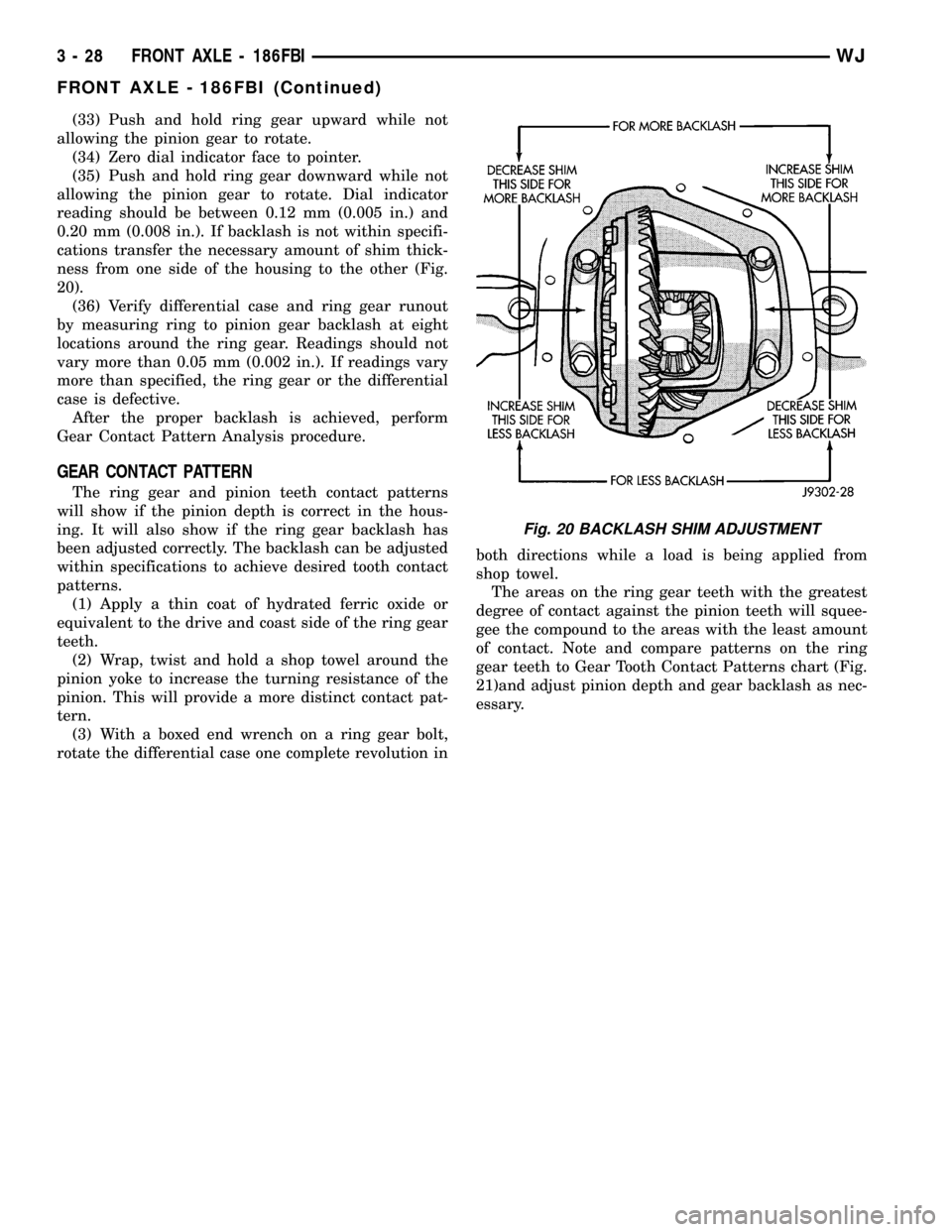
cations transfer the necessary amount of shim thick-
ness from one side of the housing to the other (Fig.
20).
(36) Verify differential case and ring gear runout
by measuring ring to pinion gear backlash at eight
locations around the ring gear. Readings should not
vary more than 0.05 mm (0.002 in.). If readings vary
more than specified, the ring gear or the differential
case is defective.
After the proper backlash is achieved, perform
Gear Contact Pattern Analysis procedure.
GEAR CONTACT PATTERN
The ring gear and pinion teeth contact patterns
will show if the pinion depth is correct in the hous-
ing. It will also show if the ring gear backlash has
been adjusted correctly. The backlash can be adjusted
within specifications to achieve desired tooth contact
patterns.
(1) Apply a thin coat of hydrated ferric oxide or
equivalent to the drive and coast side of the ring gear
teeth.
(2) Wrap, twist and hold a shop towel around the
pinion yoke to increase the turning resistance of the
pinion. This will provide a more distinct contact pat-
tern.
(3) With a boxed end wrench on a ring gear bolt,
rotate the differential case one complete revolution inboth directions while a load is being applied from
shop towel.
The areas on the ring gear teeth with the greatest
degree of contact against the pinion teeth will squee-
gee the compound to the areas with the least amount
of contact. Note and compare patterns on the ring
gear teeth to Gear Tooth Contact Patterns chart (Fig.
21)and adjust pinion depth and gear backlash as nec-
essary.
Fig. 20 BACKLASH SHIM ADJUSTMENT
3 - 28 FRONT AXLE - 186FBIWJ
FRONT AXLE - 186FBI (Continued)
Page 74 of 2199
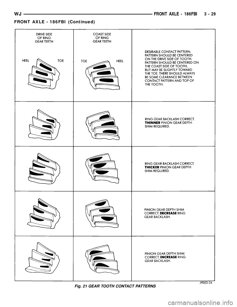
Fig. 21 GEAR TOOTH CONTACT PATTERNS
WJFRONT AXLE - 186FBI 3 - 29
FRONT AXLE - 186FBI (Continued)
Page 75 of 2199
DIFFERENTIAL BEARING PRELOAD CHECK
The final check on the differential assembly before
installing the axles is torque to rotate pinion and dif-
ferential combined. This will verify the correct differ-
ential bearing preload.Torque to rotate the differential and pinion should
be the torque to rotate the pinion plus 0.79-1.24 N´m
(7-11 in. lbs.).
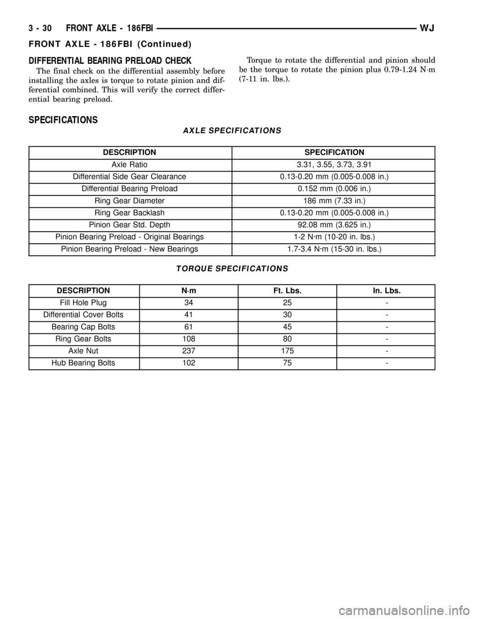
SPECIFICATIONS
AXLE SPECIFICATIONS
DESCRIPTION SPECIFICATION
Axle Ratio 3.31, 3.55, 3.73, 3.91
Differential Side Gear Clearance 0.13-0.20 mm (0.005-0.008 in.)
Differential Bearing Preload 0.152 mm (0.006 in.)
Ring Gear Diameter 186 mm (7.33 in.)
Ring Gear Backlash 0.13-0.20 mm (0.005-0.008 in.)
Pinion Gear Std. Depth 92.08 mm (3.625 in.)
Pinion Bearing Preload - Original Bearings 1-2 N´m (10-20 in. lbs.)
Pinion Bearing Preload - New Bearings 1.7-3.4 N´m (15-30 in. lbs.)
TORQUE SPECIFICATIONS
DESCRIPTION N´m Ft. Lbs. In. Lbs.
Fill Hole Plug 34 25 -
Differential Cover Bolts 41 30 -
Bearing Cap Bolts 61 45 -
Ring Gear Bolts 108 80 -
Axle Nut 237 175 -
Hub Bearing Bolts 102 75 -
3 - 30 FRONT AXLE - 186FBIWJ
FRONT AXLE - 186FBI (Continued)
Page 79 of 2199
AXLE SHAFTS
REMOVAL
If the axle shaft and hub bearing are being
removed in order to service another component, the
axle shaft and hub bearing can be removed as an
assembly.
(1) Raise and support the vehicle.
(2) Remove the wheel and tire assembly.
(3) Remove brake caliper, rotor and ABS wheel
speed sensor.
(4) Remove cotter pin, nut retainer and axle nut.
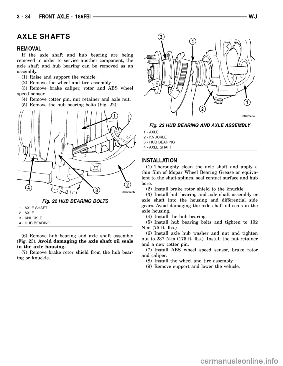
(5) Remove the hub bearing bolts (Fig. 22).
(6) Remove hub bearing and axle shaft assembly
(Fig. 23).Avoid damaging the axle shaft oil seals
in the axle housing.
(7) Remove brake rotor shield from the hub bear-
ing or knuckle.
INSTALLATION
(1) Thoroughly clean the axle shaft and apply a
thin film of Mopar Wheel Bearing Grease or equiva-
lent to the shaft splines, seal contact surface and hub
bore.
(2) Install brake rotor shield to the knuckle.
(3) Install hub bearing and axle shaft assembly or
axle shaft into the housing and differential side
gears. Avoid damaging the axle shaft oil seals in the
axle housing.
(4) Install the hub bearing.
(5) Install hub bearing bolts and tighten to 102
N´m (75 ft. lbs.).
(6) Install axle hub washer and nut and tighten
nut to 237 N´m (175 ft. lbs.). Install the nut retainer
and a new cotter pin.
(7) Install ABS wheel speed sensor, brake rotor
and caliper.
(8) Install the wheel and tire assembly.
(9) Remove support and lower the vehicle.
Fig. 22 HUB BEARING BOLTS
1 - AXLE SHAFT
2 - AXLE
3 - KNUCKLE
4 - HUB BEARING
Fig. 23 HUB BEARING AND AXLE ASSEMBLY
1 - AXLE
2 - KNUCKLE
3 - HUB BEARING
4 - AXLE SHAFT
3 - 34 FRONT AXLE - 186FBIWJ
Page 82 of 2199

INSTALLATION
(1) Pack the bearing caps 1/3 full of wheel bearing
lubricant. Apply extreme pressure (EP), lithium-base
lubricant to aid in installation.
(2) Position the spider in the yoke. Insert the seals
and bearings, then tap bearing caps into the yoke
bores far enough to hold the spider in position.
(3) Place the socket (driver) against one bearing
cap. Position the yoke with the socket in a vise.
(4) Tighten the vise to force the bearing caps into
the yoke. Force the caps enough to install the retain-
ing clips.
(5) Install the bearing cap retaining clips.
(6) Install axle shaft.
PINION SEAL
REMOVAL
(1) Raise and support the vehicle.
(2) Remove wheel and tire assemblies.
(3) Remove brake rotors and calipers, refer to 5
Brakes for procedures.
(4) Mark propeller shaft and pinion companion
flange for installation reference.
(5) Remove the propeller shaft from the pinion
companion flange.
(6) Rotate the pinion gear a minimum of ten times
and verify the pinion rotates smoothly.
(7) Record torque necessary to rotate the pinion
gear with a inch pound torque wrench.
(8) Using a short piece of pipe and Spanner
Wrench 6958 to hold the pinion companion flange
and remove the pinion nut and washer.
(9) Remove pinion companion flange with Remover
C-452 and Flange Wrench C-3281.
(10) Remove pinion seal with Remover 7794-A and
a slide hammer (Fig. 31).
INSTALLATION
(1) Apply a light coating of gear lubricant on the
lip of pinion seal. Install seal with an appropriate
installer (Fig. 32).
(2) Install pinion companion flange on the pinion
gear with Installer W-162-D, Cup 8109 and Wrench
6958.
CAUTION: Never exceed the minimum tightening
torque 298 N´m (220 ft. lbs.) while installing pinion
nut at this point. Damage to collapsible spacer or
bearings may result.
(3) Install the pinion washer and anewnut on
the pinion gear.Tighten the nut only enough to
remove the shaft end play.
Fig. 29 AXLE SHAFT OUTER U-JOINT
1 - SHAFT YOKE
2 - BEARING CAP
3 - SNAP RINGS
4 - BEARING CAP
5 - SPINDLE YOKE
6 - BEARING
7 - BEARING CAP
8 - SNAP RINGS
9 - BEARING CAP
Fig. 30 YOKE BEARING CAP
1 - LARGE-DIAMETER SOCKET
2 - VISE
3 - SMALL-DIAMETER SOCKET
WJFRONT AXLE - 186FBI 3 - 37
AXLE - U-JOINT (Continued)
Page 84 of 2199
(6) Install propeller shaft with installation refer-
ence marks aligned.
(7) Fill differential with gear lubricant.
(8) Install brake rotors and calipers.
(9) Install wheel and tire assemblies.
(10) Lower the vehicle.
COLLAPSIBLE SPACER
REMOVAL
(1) Raise and support the vehicle.
(2) Remove wheel and tire assemblies.
(3) Remove brake rotors and calipers. Refer to 5
Brakes for procedures.
(4) Mark the propeller shaft and pinion companion
flange for installation reference.
(5) Remove propeller shaft from the pinion com-
panion flange.
(6) Rotate pinion gear a minimum of ten times and
verify pinion rotates smoothly.
(7) Record pinion gear rotating torque with a
torque wrench for installation reference.
(8) Remove pinion nut and washer. Using a short
piece of pipe and Spanner Wrench 6958 to hold the
pinion companion flange.
(9) Remove pinion companion flange with Remover
C-452 and Flange Wrench C-3281.
(10) Remove pinion shaft seal with Remover
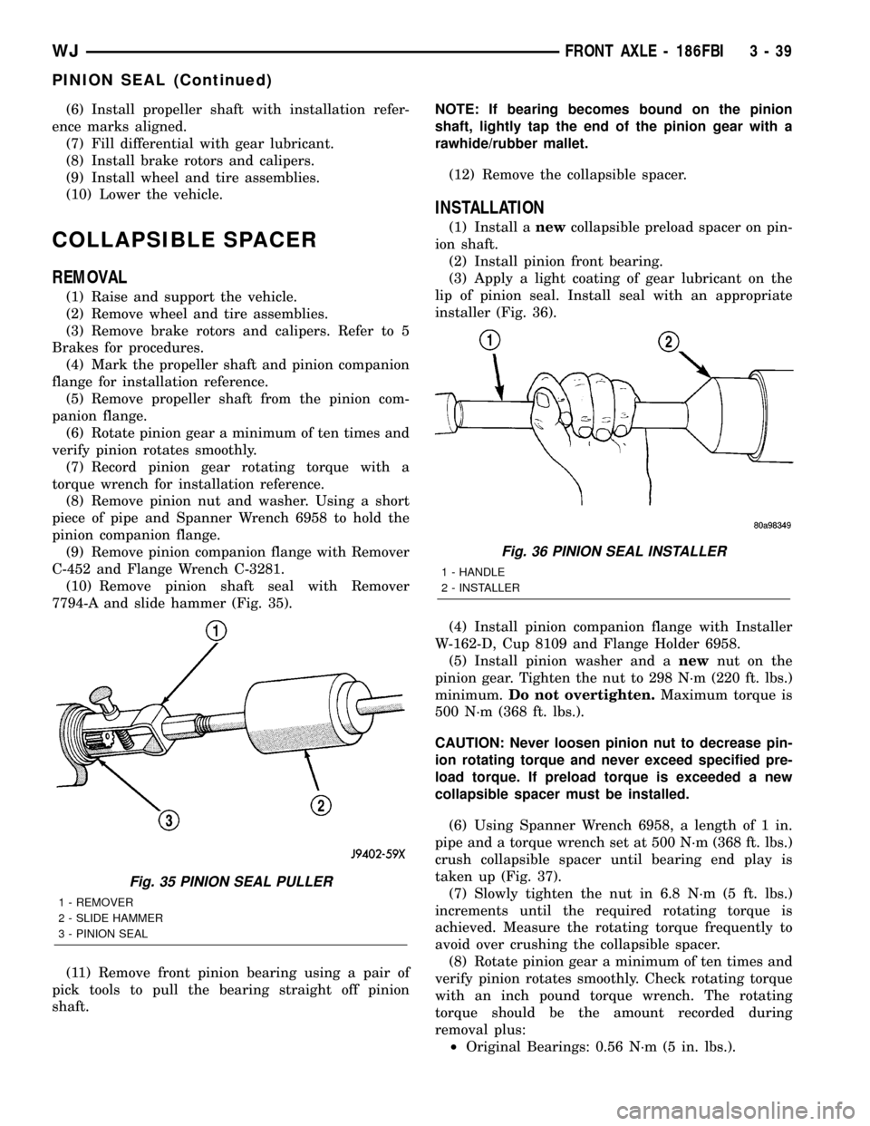
7794-A and slide hammer (Fig. 35).
(11) Remove front pinion bearing using a pair of
pick tools to pull the bearing straight off pinion
shaft.NOTE: If bearing becomes bound on the pinion
shaft, lightly tap the end of the pinion gear with a
rawhide/rubber mallet.
(12) Remove the collapsible spacer.
INSTALLATION
(1) Install anewcollapsible preload spacer on pin-
ion shaft.
(2) Install pinion front bearing.
(3) Apply a light coating of gear lubricant on the
lip of pinion seal. Install seal with an appropriate
installer (Fig. 36).
(4) Install pinion companion flange with Installer
W-162-D, Cup 8109 and Flange Holder 6958.
(5) Install pinion washer and anewnut on the
pinion gear. Tighten the nut to 298 N´m (220 ft. lbs.)
minimum.Do not overtighten.Maximum torque is
500 N´m (368 ft. lbs.).
CAUTION: Never loosen pinion nut to decrease pin-
ion rotating torque and never exceed specified pre-
load torque. If preload torque is exceeded a new
collapsible spacer must be installed.
(6) Using Spanner Wrench 6958, a length of 1 in.
pipe and a torque wrench set at 500 N´m (368 ft. lbs.)
crush collapsible spacer until bearing end play is
taken up (Fig. 37).
(7) Slowly tighten the nut in 6.8 N´m (5 ft. lbs.)
increments until the required rotating torque is
achieved. Measure the rotating torque frequently to
avoid over crushing the collapsible spacer.
(8) Rotate pinion gear a minimum of ten times and
verify pinion rotates smoothly. Check rotating torque
with an inch pound torque wrench. The rotating
torque should be the amount recorded during
removal plus:
²Original Bearings: 0.56 N´m (5 in. lbs.).
Fig. 35 PINION SEAL PULLER
1 - REMOVER
2 - SLIDE HAMMER
3 - PINION SEAL
Fig. 36 PINION SEAL INSTALLER
1 - HANDLE
2 - INSTALLER
WJFRONT AXLE - 186FBI 3 - 39
PINION SEAL (Continued)