2002 JEEP GRAND CHEROKEE Bearings
[x] Cancel search: BearingsPage 75 of 2199

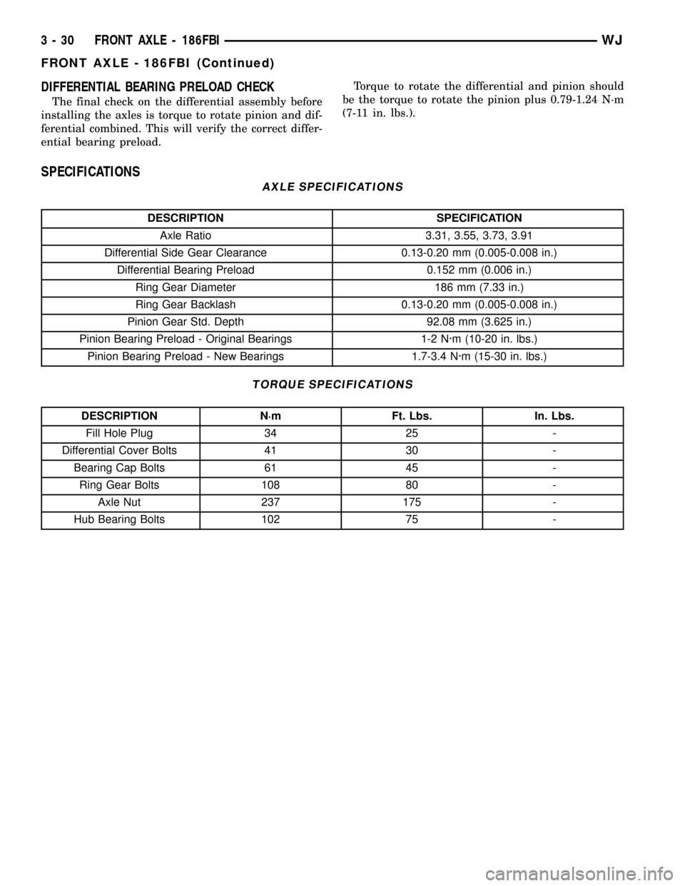
DIFFERENTIAL BEARING PRELOAD CHECK
The final check on the differential assembly before
installing the axles is torque to rotate pinion and dif-
ferential combined. This will verify the correct differ-
ential bearing preload.Torque to rotate the differential and pinion should
be the torque to rotate the pinion plus 0.79-1.24 N´m
(7-11 in. lbs.).
SPECIFICATIONS
AXLE SPECIFICATIONS
DESCRIPTION SPECIFICATION
Axle Ratio 3.31, 3.55, 3.73, 3.91
Differential Side Gear Clearance 0.13-0.20 mm (0.005-0.008 in.)
Differential Bearing Preload 0.152 mm (0.006 in.)
Ring Gear Diameter 186 mm (7.33 in.)
Ring Gear Backlash 0.13-0.20 mm (0.005-0.008 in.)
Pinion Gear Std. Depth 92.08 mm (3.625 in.)
Pinion Bearing Preload - Original Bearings 1-2 N´m (10-20 in. lbs.)
Pinion Bearing Preload - New Bearings 1.7-3.4 N´m (15-30 in. lbs.)
TORQUE SPECIFICATIONS
DESCRIPTION N´m Ft. Lbs. In. Lbs.
Fill Hole Plug 34 25 -
Differential Cover Bolts 41 30 -
Bearing Cap Bolts 61 45 -
Ring Gear Bolts 108 80 -
Axle Nut 237 175 -
Hub Bearing Bolts 102 75 -
3 - 30 FRONT AXLE - 186FBIWJ
FRONT AXLE - 186FBI (Continued)
Page 82 of 2199

INSTALLATION
(1) Pack the bearing caps 1/3 full of wheel bearing
lubricant. Apply extreme pressure (EP), lithium-base
lubricant to aid in installation.
(2) Position the spider in the yoke. Insert the seals
and bearings, then tap bearing caps into the yoke
bores far enough to hold the spider in position.
(3) Place the socket (driver) against one bearing
cap. Position the yoke with the socket in a vise.
(4) Tighten the vise to force the bearing caps into
the yoke. Force the caps enough to install the retain-
ing clips.
(5) Install the bearing cap retaining clips.
(6) Install axle shaft.
PINION SEAL
REMOVAL
(1) Raise and support the vehicle.
(2) Remove wheel and tire assemblies.
(3) Remove brake rotors and calipers, refer to 5
Brakes for procedures.
(4) Mark propeller shaft and pinion companion
flange for installation reference.
(5) Remove the propeller shaft from the pinion
companion flange.
(6) Rotate the pinion gear a minimum of ten times
and verify the pinion rotates smoothly.
(7) Record torque necessary to rotate the pinion
gear with a inch pound torque wrench.
(8) Using a short piece of pipe and Spanner
Wrench 6958 to hold the pinion companion flange
and remove the pinion nut and washer.
(9) Remove pinion companion flange with Remover
C-452 and Flange Wrench C-3281.
(10) Remove pinion seal with Remover 7794-A and
a slide hammer (Fig. 31).
INSTALLATION
(1) Apply a light coating of gear lubricant on the
lip of pinion seal. Install seal with an appropriate
installer (Fig. 32).
(2) Install pinion companion flange on the pinion
gear with Installer W-162-D, Cup 8109 and Wrench
6958.
CAUTION: Never exceed the minimum tightening
torque 298 N´m (220 ft. lbs.) while installing pinion
nut at this point. Damage to collapsible spacer or
bearings may result.
(3) Install the pinion washer and anewnut on
the pinion gear.Tighten the nut only enough to
remove the shaft end play.
Fig. 29 AXLE SHAFT OUTER U-JOINT
1 - SHAFT YOKE
2 - BEARING CAP
3 - SNAP RINGS
4 - BEARING CAP
5 - SPINDLE YOKE
6 - BEARING
7 - BEARING CAP
8 - SNAP RINGS
9 - BEARING CAP
Fig. 30 YOKE BEARING CAP
1 - LARGE-DIAMETER SOCKET
2 - VISE
3 - SMALL-DIAMETER SOCKET
WJFRONT AXLE - 186FBI 3 - 37
AXLE - U-JOINT (Continued)
Page 84 of 2199

(6) Install propeller shaft with installation refer-
ence marks aligned.
(7) Fill differential with gear lubricant.
(8) Install brake rotors and calipers.
(9) Install wheel and tire assemblies.
(10) Lower the vehicle.
COLLAPSIBLE SPACER
REMOVAL
(1) Raise and support the vehicle.
(2) Remove wheel and tire assemblies.
(3) Remove brake rotors and calipers. Refer to 5
Brakes for procedures.
(4) Mark the propeller shaft and pinion companion
flange for installation reference.
(5) Remove propeller shaft from the pinion com-
panion flange.
(6) Rotate pinion gear a minimum of ten times and
verify pinion rotates smoothly.
(7) Record pinion gear rotating torque with a
torque wrench for installation reference.
(8) Remove pinion nut and washer. Using a short
piece of pipe and Spanner Wrench 6958 to hold the
pinion companion flange.
(9) Remove pinion companion flange with Remover
C-452 and Flange Wrench C-3281.
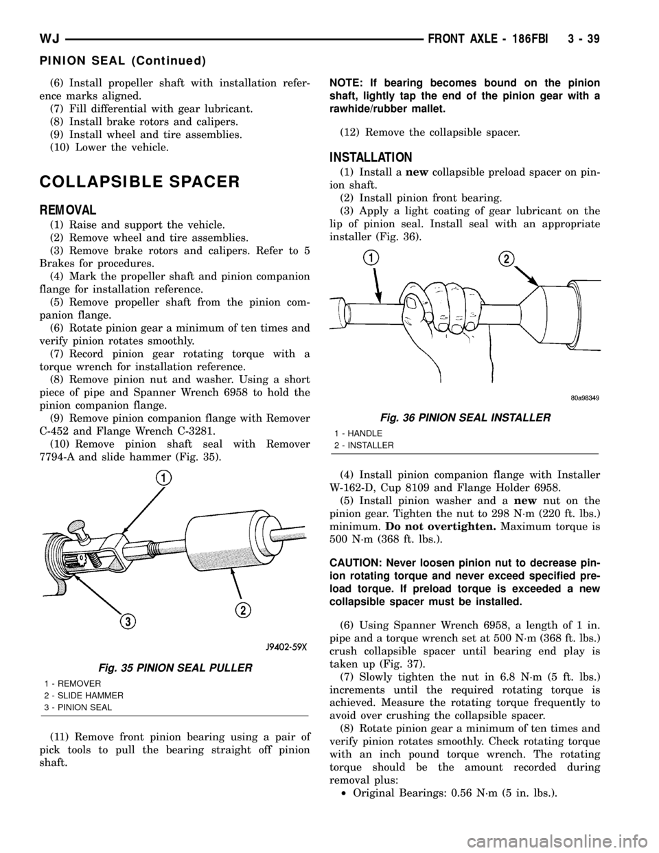
(10) Remove pinion shaft seal with Remover
7794-A and slide hammer (Fig. 35).
(11) Remove front pinion bearing using a pair of
pick tools to pull the bearing straight off pinion
shaft.NOTE: If bearing becomes bound on the pinion
shaft, lightly tap the end of the pinion gear with a
rawhide/rubber mallet.
(12) Remove the collapsible spacer.
INSTALLATION
(1) Install anewcollapsible preload spacer on pin-
ion shaft.
(2) Install pinion front bearing.
(3) Apply a light coating of gear lubricant on the
lip of pinion seal. Install seal with an appropriate
installer (Fig. 36).
(4) Install pinion companion flange with Installer
W-162-D, Cup 8109 and Flange Holder 6958.
(5) Install pinion washer and anewnut on the
pinion gear. Tighten the nut to 298 N´m (220 ft. lbs.)
minimum.Do not overtighten.Maximum torque is
500 N´m (368 ft. lbs.).
CAUTION: Never loosen pinion nut to decrease pin-
ion rotating torque and never exceed specified pre-
load torque. If preload torque is exceeded a new
collapsible spacer must be installed.
(6) Using Spanner Wrench 6958, a length of 1 in.
pipe and a torque wrench set at 500 N´m (368 ft. lbs.)
crush collapsible spacer until bearing end play is
taken up (Fig. 37).
(7) Slowly tighten the nut in 6.8 N´m (5 ft. lbs.)
increments until the required rotating torque is
achieved. Measure the rotating torque frequently to
avoid over crushing the collapsible spacer.
(8) Rotate pinion gear a minimum of ten times and
verify pinion rotates smoothly. Check rotating torque
with an inch pound torque wrench. The rotating
torque should be the amount recorded during
removal plus:
²Original Bearings: 0.56 N´m (5 in. lbs.).
Fig. 35 PINION SEAL PULLER
1 - REMOVER
2 - SLIDE HAMMER
3 - PINION SEAL
Fig. 36 PINION SEAL INSTALLER
1 - HANDLE
2 - INSTALLER
WJFRONT AXLE - 186FBI 3 - 39
PINION SEAL (Continued)
Page 85 of 2199

²New Bearings: 1.7 to 3.4 N´m (15 to 30 in. lbs.).
(9) Install propeller shaft with reference marks
aligned.
(10) Install brake rotors and calipers.
(11) Add gear lubricant if necessary.
(12) Install wheel and tire assemblies.
(13) Lower vehicle.
DIFFERENTIAL
REMOVAL
(1) Raise and support the vehicle.
(2) Remove lubricant fill hole plug from the differ-
ential housing cover.
(3) Remove differential cover and drain lubricant.
(4) Clean the housing cavity with a flushing oil,
light engine oil or lint free cloth.Never use water,
steam, kerosene or gasoline for cleaning.
(5) Remove hub bearings and axle shafts.
(6) Note installation reference letters stamped on
the bearing caps and housing machined sealing sur-
face (Fig. 38).
(7) Loosen the differential bearing cap bolts.
(8) Position Spreader W-129-B with Adapter Kit
6987B on differential locating holes (Fig. 39). Install
hold down clamps and tighten the tool turnbuckle
finger-tight.
Fig. 37 PINION COMPANION FLANGE
1 - COMPANION FLNAGE
2 - DIFFERENTIAL HOUSING
3 - SPANNER WRENCH
Fig. 38 BEARING CAP IDENTIFICATION
1 - REFERENCE LETTERS
2 - REFERENCE LETTERS
Fig. 39 DIFFERENTIAL SPREADER LOCATION
1 - DIFFERENTIAL HOUSING
2 - ADAPTER
3 - HOLD DOWN CLAMPS
4 - SPREADER
5 - TURNBUCKLE
3 - 40 FRONT AXLE - 186FBIWJ
COLLAPSIBLE SPACER (Continued)
Page 88 of 2199

INSTALLATION
NOTE: If replacement differential bearings or differ-
ential case are being installed, differential side
bearing shim requirements may change. Refer to
Adjustments (Differential Bearing Preload and Gear
Backlash) to determine the proper shim selection.
(1) Position Spreader W-129-B with Adapter Kit
6987B on differential locating holes. Install hold
down clamps and tighten the tool turnbuckle finger-
tight.
(2) Install a Pilot Stud C-3288-B at the left side of
the differential housing. Attach Dial Indicator C-3339
to pilot stud. Load the indicator plunger against the
opposite side of the housing and zero the indicator.
(3) Spread the housing enough to install the case
in the housing. Measure the distance with the dial
indicator.
CAUTION: Never spread the housing over 0.50 mm
(0.020 in). If housing is over-spread, it could dis-
torted and damaged the housing.
(4) Remove the dial indicator.
(5) Install differential case in the housing (Fig.
46). Make sure the differential bearing cups remain
on the bearings and the preload shims remain
between the face of the bearing cup and housing. Tap
the differential case to ensure the bearings cups and
shims are fully seated in the housing.
CAUTION: On a Vari-lokTdifferential the oil feed
tube must be pointed at the bottom of the housing.
If differential is installed with the oil feed tube
pointed at the top, the anti-rotation tabs will be
damaged.
(6) Install the bearing caps at their original loca-
tions (Fig. 47).
(7) Loosely install differential bearing cap bolts.
(8) Remove axle housing spreader.
(9) Tighten the bearing cap bolts to 61 N´m (45 ft.
lbs.).
(10) Install the hub bearings and axle shafts.
Fig. 46 DIFFERENTIAL CASE REMOVAL
1 - DIFFERENTIAL HOUSING
2 - DIFFERENTIAL CASE
3 - BEARING CUPS
Fig. 47 Bearing Cap Reference
1 - REFERENCE LETTERS
2 - REFERENCE LETTERS
WJFRONT AXLE - 186FBI 3 - 43
DIFFERENTIAL (Continued)
Page 89 of 2199

(11) Apply a bead 6.35mm (1/4 inch) of red Mopar
Silicone Rubber Sealant or equivalent to the housing
cover (Fig. 48).
CAUTION: If cover is not installed within 3 to 5 min-
utes, the cover must be cleaned and new RTV
applied or adhesion quality will be compromised.
(12) Install differential cover and tighten cover
bolts in a criss-cross pattern to 41 N´m (30 ft. lbs.).
(13) Fill differential with gear lubricant to bottom
of the fill plug hole.
(14) Tighten fill plug to 34 N´m (25 ft. lbs.).
(15) Remove support and lower the vehicle.
DIFFERENTIAL CASE
BEARINGS
REMOVAL
(1) Remove differential case from housing.
(2) Remove bearings from the differential case
with Puller C-293-PA, Adapters 8352 and Plug
SP-3289 (Fig. 49).
INSTALLATION
NOTE: If replacement differential side bearings or
differential case are being installed, differential side
bearing shim requirements may change. Refer to
Adjustments (Differential Bearing Preload and Gear
Backlash) to determine the proper shim selection.
CAUTION: Vari-lokTplenum must be fully seated
against the differential case prior to installing the
ring gear side differential bearing.
(1) Install differential side bearings with Handle
C-4171 and Installer C-3726-A (Fig. 50).
(2) Install differential in housing.
Fig. 48 DIFFERENTIAL COVER
1 - COVER
2 - SEALANT
3 - SEALANT BEADFig. 49 DIFFERENTIAL CASE BEARING
1 - ADAPTERS
2 - BEARING
3 - DIFFERENTIAL
4 - PLUG
5 - PULLER
3 - 44 FRONT AXLE - 186FBIWJ
DIFFERENTIAL (Continued)
Page 90 of 2199

PINION GEAR/RING GEAR
REMOVAL
NOTE: The ring gear and pinion are serviced as a
matched set. Nevar replace one gear without replac-
ing the other matching gear.
(1) Raise and support vehicle
(2) Mark pinion companion flange and propeller
shaft for installation alignment.
(3) Remove propeller shaft from pinion companion
flange and tie propeller shaft to underbody.
(4) Remove differential from axle housing.
(5) Place differential case in a vise with soft metal
jaw (Fig. 51).
(6) Remove bolts holding ring gear to differential
case.
NOTE: On Veri-LokTdifferential the side bearing
and oil feed plenum must be removed before
removing the ring gear bolts.
(7) Driver ring gear off the differential case with a
rawhide hammer (Fig. 51).(8) With Spanner Wrench 6958 and a short length
of 1 in. pipe, hold pinion companion flange and
remove pinion nut and washer (Fig. 52).
(9) Remove pinion companion flange from pinion
shaft with Remover C-452 and Flange Wrench
C-3281.
Fig. 50 DIFFERENTIAL CASE BEARING
1 - INSTALLER
2 - HANDLE
Fig. 51 RING GEAR
1 - DIFFERENTIAL CASE
2 - RING GEAR
3 - HAMMER
Fig. 52 Pinion Flange
1 - PINION FLANGE
2 - FRONT AXLE
3 - SPANNER WRENCH
WJFRONT AXLE - 186FBI 3 - 45
DIFFERENTIAL CASE BEARINGS (Continued)
Page 93 of 2199

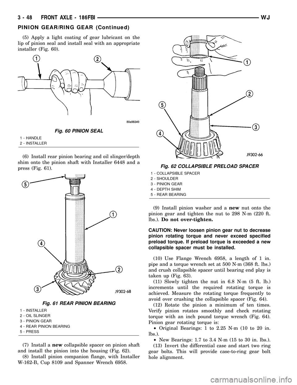
(5) Apply a light coating of gear lubricant on the
lip of pinion seal and install seal with an appropriate
installer (Fig. 60).
(6) Install rear pinion bearing and oil slinger/depth
shim onto the pinion shaft with Installer 6448 and a
press (Fig. 61).
(7) Install anewcollapsible spacer on pinion shaft
and install the pinion into the housing (Fig. 62).
(8) Install pinion companion flange, with Installer
W-162-B, Cup 8109 and Spanner Wrench 6958.(9) Install pinion washer and anewnut onto the
pinion gear and tighten the nut to 298 N´m (220 ft.
lbs.).Do not over-tighten.
CAUTION: Never loosen pinion gear nut to decrease
pinion rotating torque and never exceed specified
preload torque. If preload torque is exceeded a new
collapsible spacer must be installed.
(10) Use Flange Wrench 6958, a length of 1 in.
pipe and a torque wrench set at 500 N´m (368 ft. lbs.)
and crush collapsible spacer until bearing end play is
taken up (Fig. 63).
(11) Slowly tighten the nut in 6.8 N´m (5 ft. lb.)
increments until the required rotating torque is
achieved. Measure the rotating torque frequently to
avoid over crushing the collapsible spacer (Fig. 64).
(12) Rotate the pinion a minimum of ten times.
Verify pinion rotates smoothly and check rotating
torque with an inch pound torque wrench (Fig. 64).
Pinion gear rotating torque is:
²Original Bearings: 1 to 2.25 N´m (10 to 20 in.
lbs.).
²New Bearings: 1.7 to 3.4 N´m (15 to 30 in. lbs.).
(13) Invert the differential case and start two ring
gear bolts. This will provide case-to-ring gear bolt
hole alignment.
Fig. 60 PINION SEAL
1 - HANDLE
2 - INSTALLER
Fig. 61 REAR PINION BEARING
1 - INSTALLER
2 - OIL SLINGER
3 - PINION GEAR
4 - REAR PINION BEARING
5 - PRESS
Fig. 62 COLLAPSIBLE PRELOAD SPACER
1 - COLLAPSIBLE SPACER
2 - SHOULDER
3 - PINION GEAR
4 - DEPTH SHIM
5 - REAR BEARING
3 - 48 FRONT AXLE - 186FBIWJ
PINION GEAR/RING GEAR (Continued)