2002 JEEP GRAND CHEROKEE Amplifier
[x] Cancel search: AmplifierPage 1154 of 2199

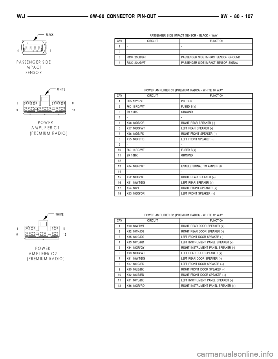
PASSENGER SIDE IMPACT SENSOR - BLACK 4 WAY
CAV CIRCUIT FUNCTION
1- -
2- -
3 R134 20LB/BR PASSENGER SIDE IMPACT SENSOR GROUND
4 R132 20LG/VT PASSENGER SIDE IMPACT SENSOR SIGNAL
POWER AMPLIFIER C1 (PREMIUM RADIO) - WHITE 18 WAY
CAV CIRCUIT FUNCTION
1 D25 18YL/VT PCI BUS
2 F60 16RD/WT FUSED B(+)
3 Z9 16BK GROUND
4- -
5 X58 18DB/OR RIGHT REAR SPEAKER (-)
6 X57 18DG/WT LEFT REAR SPEAKER (-)
7 X56 18DB/PK RIGHT FRONT SPEAKER (-)
8 X55 18BR/RD LEFT FRONT SPEAKER (-)
9- -
10 F60 16RD/WT FUSED B(+)
11 Z9 16BK GROUND
12 - -
13 X64 18BR/WT ENABLE SIGNAL TO AMPLIFIER
14 - -
15 X52 18DB/WT RIGHT REAR SPEAKER (+)
16 X51 18WT/DG LEFT REAR SPEAKER (+)
17 X54 18VT RIGHT FRONT SPEAKER (+)
18 X53 18DG/OR LEFT FRONT SPEAKER (+)
POWER AMPLIFIER C2 (PREMIUM RADIO) - WHITE 12 WAY
CAV CIRCUIT FUNCTION
1 X90 18WT/VT RIGHT REAR DOOR SPEAKER (+)
2 X92 18TN/DG RIGHT REAR DOOR SPEAKER (-)
3 X85 18LG/DG LEFT FRONT DOOR SPEAKER (-)
4 X83 18YL/RD LEFT INSTRUMENT PANEL SPEAKER (+)
5 X84 18OR/GY RIGHT INSTRUMENT PANEL SPEAKER (-)
6 X93 18DG/WT LEFT REAR DOOR SPEAKER (+)
7 X91 18WT/DG LEFT REAR DOOR SPEAKER (-)
8 X87 18LG/RD LEFT FRONT DOOR SPEAKER (+)
9 X80 18LB/BK RIGHT FRONT DOOR SPEAKER (-)
10 X82 18LB/RD RIGHT FRONT DOOR SPEAKER (+)
11 X81 18YL/BK LEFT INSTRUMENT PANEL SPEAKER (-)
12 X86 18OR/RD RIGHT INSTRUMENT PANEL SPEAKER (+)
WJ8W-80 CONNECTOR PIN-OUT 8W - 80 - 107
Page 1158 of 2199

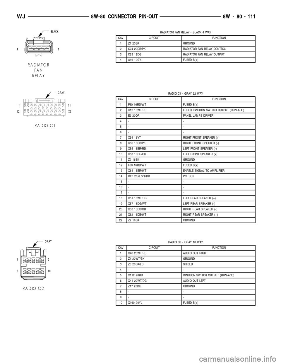
RADIATOR FAN RELAY - BLACK 4 WAY
CAV CIRCUIT FUNCTION
1 Z1 20BK GROUND
2 C24 20DB/PK RADIATOR FAN RELAY CONTROL
3 C23 12DG RADIATOR FAN RELAY OUTPUT
4 A16 12GY FUSED B(+)
RADIO C1 - GRAY 22 WAY
CAV CIRCUIT FUNCTION
1 F60 16RD/WT FUSED B(+)
2 X12 16WT/RD FUSED IGNITION SWITCH OUTPUT (RUN-ACC)
3 E2 20OR PANEL LAMPS DRIVER
4- -
5- -
6- -
7 X54 18VT RIGHT FRONT SPEAKER (+)
8 X56 18DB/PK RIGHT FRONT SPEAKER (-)
9 X55 18BR/RD LEFT FRONT SPEAKER (-)
10 X53 18DG/OR LEFT FRONT SPEAKER (+)
11 Z9 16BK GROUND
12 F60 16RD/WT FUSED B(+)
13 X64 18BR/WT ENABLE SIGNAL TO AMPLIFIER
14 D25 20YL/VT/DB PCI BUS
15 - -
16 - -
17 - -
18 X51 18WT/DG LEFT REAR SPEAKER (+)
19 X57 18DG/WT LEFT REAR SPEAKER (-)
20 X58 18DB/OR RIGHT REAR SPEAKER (-)
21 X52 18DB/WT RIGHT REAR SPEAKER (+)
22 Z9 16BK GROUND
RADIO C2 - GRAY 10 WAY
CAV CIRCUIT FUNCTION
1 X40 20WT/RD AUDIO OUT RIGHT
2 Z4 20WT/BK GROUND
3 Z5 20BK/LB SHIELD
4- -
5 X112 20RD IGNITION SWITCH OUTPUT (RUN-ACC)
6 X41 20WT/DG AUDIO OUT LEFT
7 Z17 20BK GROUND
8- -
9- -
10 X160 20YL FUSED B(+)
WJ8W-80 CONNECTOR PIN-OUT 8W - 80 - 111
Page 1184 of 2199

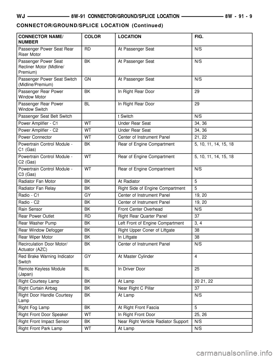
CONNECTOR NAME/
NUMBERCOLOR LOCATION FIG.
Passenger Power Seat Rear
Riser MotorRD At Passenger Seat N/S
Passenger Power Seat
Recliner Motor (Midline/
Premium)BK At Passenger Seat N/S
Passenger Power Seat Switch
(Midline/Premium)GN At Passenger Seat N/S
Passenger Rear Power
Window MotorBK In Right Rear Door 29
Passenger Rear Power
Window SwitchBL In Right Rear Door 29
Passenger Seat Belt Switch t Switch N/S
Power Amplifier - C1 WT Under Rear Seat 34, 36
Power Amplifier - C2 WT Under Rear Seat 34, 36
Power Connector WT Center of Instrument Panel 21, 22
Powertrain Control Module -
C1 (Gas)BK Rear of Engine Compartment 5, 10, 11, 14, 15, 18
Powertrain Control Module -
C2 (Gas)WT Rear of Engine Compartment 5, 10, 11, 14, 15, 18
Powertrain Control Module -
C3 (Gas)WT Rear of Engine Compartment N/S
Radiator Fan Motor BK At Radiator 5
Radiator Fan Relay BK Right Side of Engine Compartment 5
Radio - C1 GY Center of Instrument Panel 19, 20
Radio - C2 BK Center of Instrument Panel 19, 20
Rain Sensor BK Front Center Overhead N/S
Rear Power Outlet RD Right Rear Quarter Panel 37
Rear Washer Pump BK Left Front of Engine Compartment 3, 4
Rear Window Defogger BK Right Upper Coner of Liftgate 38
Rear Wiper Motor BK In Liftgate 38
Recirculation Door Motor/
Actuator (AZC)BK Center of Instrument Panel N/S
Red Brake Warning Indicator
SwitchGY At Master Cylinder 4
Remote Keyless Module
(Japan)BL In Driver Door 25
Right Courtesy Lamp BK At Lamp 20 21, 22
Right Curtain Airbag BK Near Right C Pillar 37
Right Door Handle Courtesy
LampBK At Lamp N/S
Right Fog Lamp BK At Right Front Fascia 5
Right Front Door Speaker WT In Right Front Door 25, 26
Right Front Impact Sensor BK Near Right Verticle Radiator Support N/S
Right Front Park Lamp WT At Lamp N/S
WJ8W-91 CONNECTOR/GROUND/SPLICE LOCATION 8W - 91 - 9
CONNECTOR/GROUND/SPLICE LOCATION (Continued)
Page 1191 of 2199

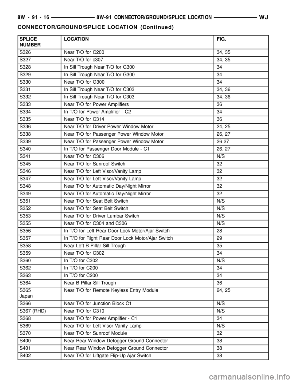
SPLICE
NUMBERLOCATION FIG.
S326 Near T/O for C200 34, 35
S327 Near T/O for c307 34, 35
S328 In Sill Trough Near T/O for G300 34
S329 In Sill Trough Near T/O for G300 34
S330 Near T/O for G300 34
S331 In Sill Trough Near T/O for C303 34, 36
S332 In Sill Trough Near T/O for C303 34, 36
S333 Near T/O for Power Amplifiers 36
S334 In T/O for Power Amplifier - C2 34
S335 Near T/O for C314 36
S336 Near T/O for Driver Power Window Motor 24, 25
S338 Near T/O for Passenger Power Window Motor 26, 27
S339 Near T/O for Passenger Power Window Motor 26 27
S340 In T/O for Passenger Door Module - C1 26, 27
S341 Near T/O for C306 N/S
S345 Near T/O for Sunroof Switch 32
S346 Near T/O for Left Visor/Vanity Lamp 32
S347 Near T/O for Left Visor/Vanity Lamp 32
S348 Near T/O for Automatic Day/Night Mirror 32
S349 Near T/O for Automatic Day/Night Mirror 32
S351 Near T/O for Seat Belt Switch N/S
S352 Near T/O for Seat Belt Switch N/S
S353 Near T/O for Driver Lumbar Switch N/S
S355 Near T/O for C304 and C306 N/S
S356 In T/O for Left Rear Door Lock Motor/Ajar Switch 28
S357 In T/O for Right Rear Door Lock Motor/Ajar Switch 29
S358 Near Left B Pillar Sill Trough 35
S359 Near T/O for C302 34
S360 In T/O for C302 N/S
S362 In T/O for C200 34
S363 In T/O for C200 34
S364 Near B Pillar Sill Trough 36
S365
JapanNear T/O for Remote Keyless Entry Module 24, 25
S366 Near T/O for Junction Block C1 N/S
S367 (RHD) Near T/O for C310 N/S
S368 Near T/O for Power Amplifier - C1 34
S369 Near T/O for Left Visor Vanity Lamp N/S
S370 Near T/O for Sunroof Module 32
S400 Near Rear Window Defogger Ground Connector 38
S401 Near Rear Window Defogger Ground Connector 38
S402 Near T/O for Liftgate Flip-Up Ajar Switch 38
8W - 91 - 16 8W-91 CONNECTOR/GROUND/SPLICE LOCATIONWJ
CONNECTOR/GROUND/SPLICE LOCATION (Continued)
Page 1944 of 2199

(4) Install screw attaching B-pillar lower trim to
B-pillar.
(5) Install screw attaching front of B-pillar lower
trim to floor.
(6) Install screw attaching front of quarter panel
trim to floor.
(7) Install front seat shoulder belt anchor bolt.
(8) Install front seat shoulder belt height adjust-
ment knob and turning loop.
(9) Install front door sill trim (Refer to 23 - BODY/
INTERIOR/DOOR SILL TRIM - INSTALLATION).
B-PILLAR UPPER TRIM
REMOVAL
(1) Remove shoulder belt height adjustment knob.
(2) Remove front seat belt turning loop.
(3) Remove the screw attaching lower B pillar
trim.
(4) Pull lower B pillar trim out far enough to
remove upper trim panel.
(5) Grasp upper B-pillar trim and pull outward to
detach from B-pillar (Fig. 2).
INSTALLATION
(1) Position trim panel on B-pillar (Fig. 2).
(2) Ensure trim panel covers inner edge of door
opening weatherstrip and press inward to seat.
(3) Install screw attaching lower B pillar trim
panel.
(4) Install front seat belt turning loop.
(5) Install shoulder belt height adjustment knob.
CARPETS AND FLOOR MATS
REMOVAL
REMOVAL - FRONT CARPET
(1) Remove door sill trim (Refer to 23 - BODY/IN-
TERIOR/DOOR SILL TRIM - REMOVAL).
(2) Remove the B-pillar lower trim, refer to (Refer
to 23 - BODY/INTERIOR/B-PILLAR LOWER TRIM -
REMOVAL).
(3) Remove front seats (Refer to 23 - BODY/
SEATS/SEAT - REMOVAL).
(4) Remove the rear seats lower cushions (Refer to
23 - BODY/SEATS/SEAT CUSHION - REMOVAL).
(5) Remove center floor console (Refer to 23 -
BODY/INTERIOR/FLOOR CONSOLE - REMOVAL).
(6) Remove any other interfering trim or molding.
(7) Lift carpet and mat from floor panel.
REMOVAL - CARGO AREA CARPET
(1) Lift tailgate.
(2) Fold rear seat cushions forward.
(3) Remove rear seat backs (Refer to 23 - BODY/
SEATS/REAR SEAT BACK - REMOVAL).
(4) Remove the rear shoulder belts (Refer to 8 -
ELECTRICAL/RESTRAINTS/REAR SEAT BELT &
RETRACTOR - REMOVAL).
(5) Remove the retractable security cargo cover
assembly.
(6) Remove the spare tire cover.
(7) Remove the rear cargo tie down footman loops.
The side mounted footman loops are retained by
screws. The floor footman loops are riveted (Fig. 3).
(8) Remove the C pillar trim (Refer to 23 - BODY/
INTERIOR/C-PILLAR TRIM - REMOVAL).
(9) Remove the CD changer, if equipped (Refer to 8
- ELECTRICAL/AUDIO/CD CHANGER - REMOV-
AL).
(10) Remove the Infinity amp, if equipped (Refer to
8 - ELECTRICAL/AUDIO/AMPLIFIER - REMOVAL).
(11) Lift the carpet.
INSTALLATION
INSTALLATION - FRONT CARPET
(1) Carefully lay the carpet and mat on the floor
panel. Align the carpet to allow installation of the
components fastened to the floor panel.
(2) Install the center console (Refer to 23 - BODY/
INTERIOR/FLOOR CONSOLE - INSTALLATION).
(3) Install the front seats (Refer to 23 - BODY/
SEATS/SEAT - INSTALLATION).
(4) Install the rear seat cushions (Refer to 23 -
BODY/SEATS/SEAT CUSHION - INSTALLATION).
Fig. 3 Cargo Area Carpet
1 - CARGO AREA CARPET
2 - RIVET
3 - CARGO TIE-DOWN LOOP
WJINTERIOR 23 - 71
B-PILLAR LOWER TRIM (Continued)
Page 1945 of 2199

(5) Install the lower B pillar trim (Refer to 23 -
BODY/INTERIOR/B-PILLAR LOWER TRIM -
INSTALLATION).
(6) Install the door sill trim (Refer to 23 - BODY/
INTERIOR/DOOR SILL TRIM - INSTALLATION).
(7) Install any other moldings or trim panels
removed.
INSTALLATION - CARGO AREA CARPET
(1) Thoroughly clean the area with Mopar Super
Kleent, or equivalent.
(2) Lay the new carpet in.
(3) Install the ªCº pillar trim (Refer to 23 - BODY/
INTERIOR/C-PILLAR TRIM - INSTALLATION).
(4) Install the CD changer, if equipped (Refer to 8 -
ELECTRICAL/AUDIO/CD CHANGER - INSTALLA-
TION).
(5) Install the footman loops (Fig. 3).
(6) Install the rear shoulder belts (Refer to 8 -
ELECTRICAL/RESTRAINTS/REAR SEAT BELT &
RETRACTOR - INSTALLATION).
(7) Install the rear seat backs (Refer to 23 -
BODY/SEATS/REAR SEAT BACK - INSTALLA-
TION).
(8) Install the Infinity amp, if equipped (Refer to 8
- ELECTRICAL/AUDIO/AMPLIFIER - INSTALLA-
TION).
(9) Install the spare tire cover.
(10) Install the retractable security cover.
COWL TRIM
REMOVAL
(1) Remove front door sill trim (Refer to 23 -
BODY/INTERIOR/DOOR SILL TRIM - REMOVAL).
(2) Remove screws attaching cowl trim to floor.
(3) Remove plastic nut.
(4) Grasp cowl trim and pull outward to separate
from clip.
(5) Separate cowl trim from vehicle.
INSTALLATION
(1) Position cowl trim and press into place.
(2) Install screws attaching cowl trim to floor.
(3) Install plastic nut.
(4) Install front door sill trim (Refer to 23 - BODY/
INTERIOR/DOOR SILL TRIM - INSTALLATION).
C-PILLAR TRIM
REMOVAL
(1) Remove rear shoulder belt turning loop.
(2) Remove rear shoulder belt height adjustment
knob.
(3) Remove screws attaching quarter panel trim.
(4) Pull quarter panel trim outward as necessary.
(5) Grasp C-pillar upper trim and pull outward to
disengage from C-pillar (Fig. 4).
(6) Route rear shoulder belt through access hole.
(7) Separate C-pillar upper trim from vehicle.
INSTALLATION
(1) Position C-pillar upper trim at C-pillar (Fig. 4).
(2) Route rear shoulder belt through access hole.
(3) Press C-pillar upper trim onto C-pillar.
(4) Press quarter panel trim into place as neces-
sary.
(5) Ensure front edge of trim is covered by weath-
erstrip.
(6) Install screws attaching quarter panel trim.
(7) Install rear shoulder belt height adjustment
knob.
(8) Install rear shoulder belt turning loop.
23 - 72 INTERIORWJ
CARPETS AND FLOOR MATS (Continued)