2002 JEEP GRAND CHEROKEE Ignition switch
[x] Cancel search: Ignition switchPage 1171 of 2199
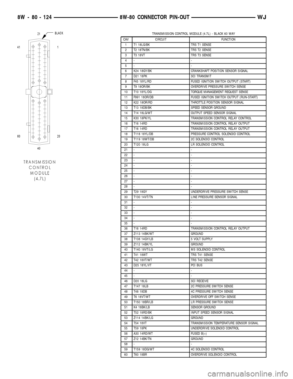
TRANSMISSION CONTROL MODULE (4.7L) - BLACK 60 WAY
CAV CIRCUIT FUNCTION
1 T1 18LG/BK TRS T1 SENSE
2 T2 18TN/BK TRS T2 SENSE
3 T3 18VT TRS T3 SENSE
4- -
5- -
6 K24 18GY/BK CRANKSHAFT POSITION SENSOR SIGNAL
7 D21 18PK SCI TRANSMIT
8 F45 18YL/RD FUSED IGNITION SWITCH OUTPUT (START)
9 T9 18OR/BK OVERDRIVE PRESSURE SWITCH SENSE
10 T10 18YL/DG TORQUE MANAGEMENT REQUEST SENSE
11 F991 18OR/DB FUSED IGNITION SWITCH OUTPUT (RUN-START)
12 K22 18OR/RD THROTTLE POSITION SENSOR SIGNAL
13 T13 18DB/BK SPEED SENSOR GROUND
14 T14 18LG/WT OUTPUT SPEED SENSOR SIGNAL
15 K30 18PK/YL TRANSMISSION CONTROL RELAY CONTROL
16 T16 14RD TRANSMISSION CONTROL RELAY OUTPUT
17 T16 14RD TRANSMISSION CONTROL RELAY OUTPUT
18 T118 18YL/DB PRESSURE CONTROL SOLENOID CONTROL
19 T119 18WT/DB 2C SOLENOID CONTROL
20 T120 18LG LR SOLENOID CONTROL
21 - -
22 - -
23 - -
24 - -
25 - -
26 - -
27 - -
28 - -
29 T29 18GY UNDERDRIVE PRESSURE SWITCH SENSE
30 T130 14VT/TN LINE PRESSURE SENSOR SIGNAL
31 - -
32 - -
33 - -
34 - -
35 - -
36 T16 14RD TRANSMISSION CONTROL RELAY OUTPUT
37 Z113 14BK/WT GROUND
38 T138 14GY/LB 5 VOLT SUPPLY
39 Z112 14BK/YL GROUND
40 T140 18VT/LG MS SOLENOID CONTROL
41 T41 18WT TRS T41 SENSE
42 T42 18VT/WT TRS T42 SENSE
43 D25 18YL/VT PCI BUS
44 - -
45 - -
46 D20 18LG SCI RECEIVE
47 T147 18LB 2C PRESSURE SWITCH SENSE
48 T48 18DB 4C PRESSURE SWITCH SENSE
49 T6 18VT/WT OVERDRIVE OFF SWITCH SENSE
50 T150 18BR/LB LR PRESSURE SWITCH SENSE
51 K4 18BK/LB SENSOR GROUND
52 T52 18RD/BK INPUT SPEED SENSOR SIGNAL
53 Z114 14BK/LG GROUND
54 T54 18VT TRANSMISSION TEMPERATURE SENSOR SIGNAL
55 T59 18PK UNDERDRIVE SOLENOID CONTROL
56 A30 14RD/WT FUSED B(+)
57 Z12 14BK/TN GROUND
58 - -
59 T159 18DG/WT 4C SOLENOID CONTROL
60 T60 18BR OVERDRIVE SOLENOID CONTROL
8W - 80 - 124 8W-80 CONNECTOR PIN-OUTWJ
Page 1172 of 2199
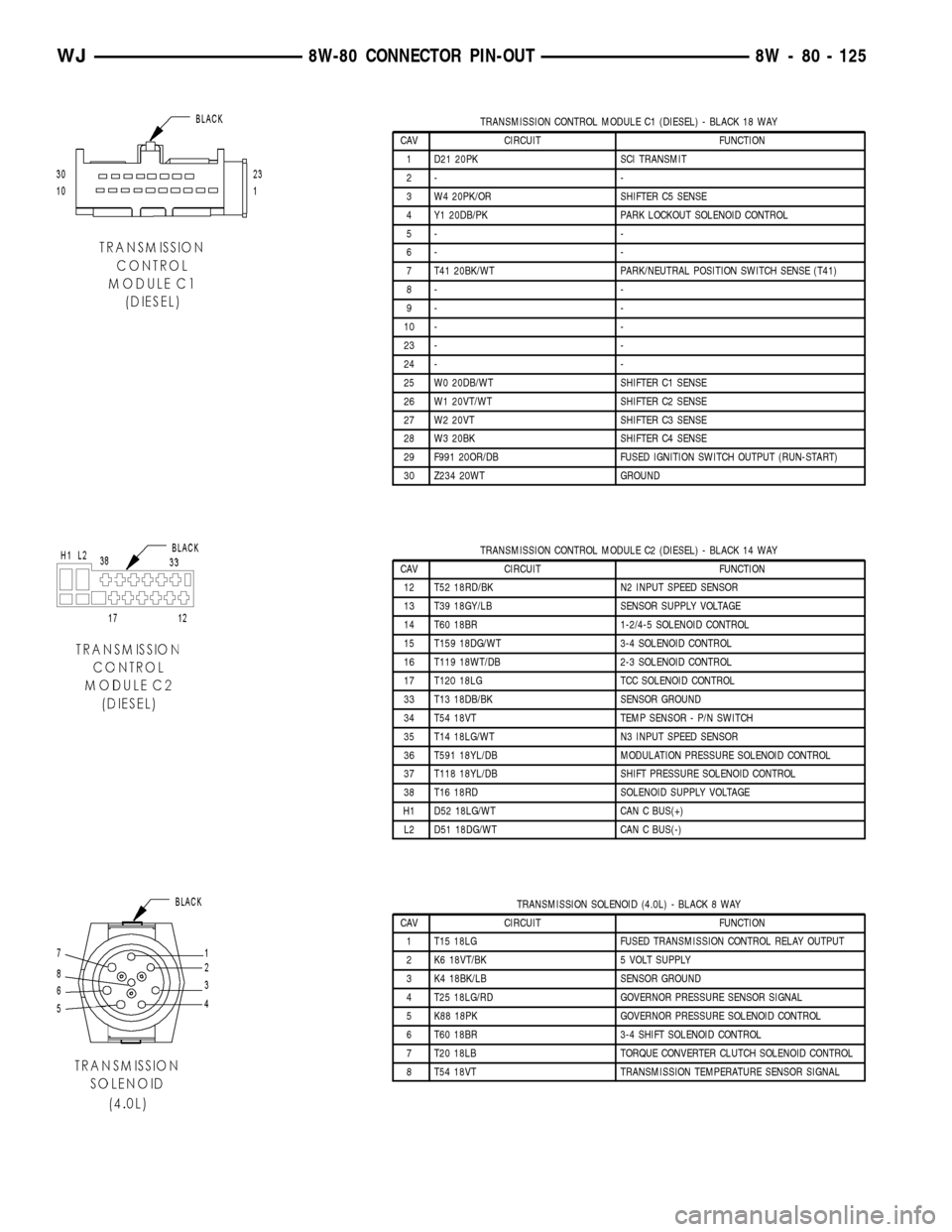
TRANSMISSION CONTROL MODULE C1 (DIESEL) - BLACK 18 WAY
CAV CIRCUIT FUNCTION
1 D21 20PK SCI TRANSMIT
2- -
3 W4 20PK/OR SHIFTER C5 SENSE
4 Y1 20DB/PK PARK LOCKOUT SOLENOID CONTROL
5- -
6- -
7 T41 20BK/WT PARK/NEUTRAL POSITION SWITCH SENSE (T41)
8- -
9- -
10 - -
23 - -
24 - -
25 W0 20DB/WT SHIFTER C1 SENSE
26 W1 20VT/WT SHIFTER C2 SENSE
27 W2 20VT SHIFTER C3 SENSE
28 W3 20BK SHIFTER C4 SENSE
29 F991 20OR/DB FUSED IGNITION SWITCH OUTPUT (RUN-START)
30 Z234 20WT GROUND
TRANSMISSION CONTROL MODULE C2 (DIESEL) - BLACK 14 WAY
CAV CIRCUIT FUNCTION
12 T52 18RD/BK N2 INPUT SPEED SENSOR
13 T39 18GY/LB SENSOR SUPPLY VOLTAGE
14 T60 18BR 1-2/4-5 SOLENOID CONTROL
15 T159 18DG/WT 3-4 SOLENOID CONTROL
16 T119 18WT/DB 2-3 SOLENOID CONTROL
17 T120 18LG TCC SOLENOID CONTROL
33 T13 18DB/BK SENSOR GROUND
34 T54 18VT TEMP SENSOR - P/N SWITCH
35 T14 18LG/WT N3 INPUT SPEED SENSOR
36 T591 18YL/DB MODULATION PRESSURE SOLENOID CONTROL
37 T118 18YL/DB SHIFT PRESSURE SOLENOID CONTROL
38 T16 18RD SOLENOID SUPPLY VOLTAGE
H1 D52 18LG/WT CAN C BUS(+)
L2 D51 18DG/WT CAN C BUS(-)
TRANSMISSION SOLENOID (4.0L) - BLACK 8 WAY
CAV CIRCUIT FUNCTION
1 T15 18LG FUSED TRANSMISSION CONTROL RELAY OUTPUT
2 K6 18VT/BK 5 VOLT SUPPLY
3 K4 18BK/LB SENSOR GROUND
4 T25 18LG/RD GOVERNOR PRESSURE SENSOR SIGNAL
5 K88 18PK GOVERNOR PRESSURE SOLENOID CONTROL
6 T60 18BR 3-4 SHIFT SOLENOID CONTROL
7 T20 18LB TORQUE CONVERTER CLUTCH SOLENOID CONTROL
8 T54 18VT TRANSMISSION TEMPERATURE SENSOR SIGNAL
WJ8W-80 CONNECTOR PIN-OUT 8W - 80 - 125
Page 1173 of 2199
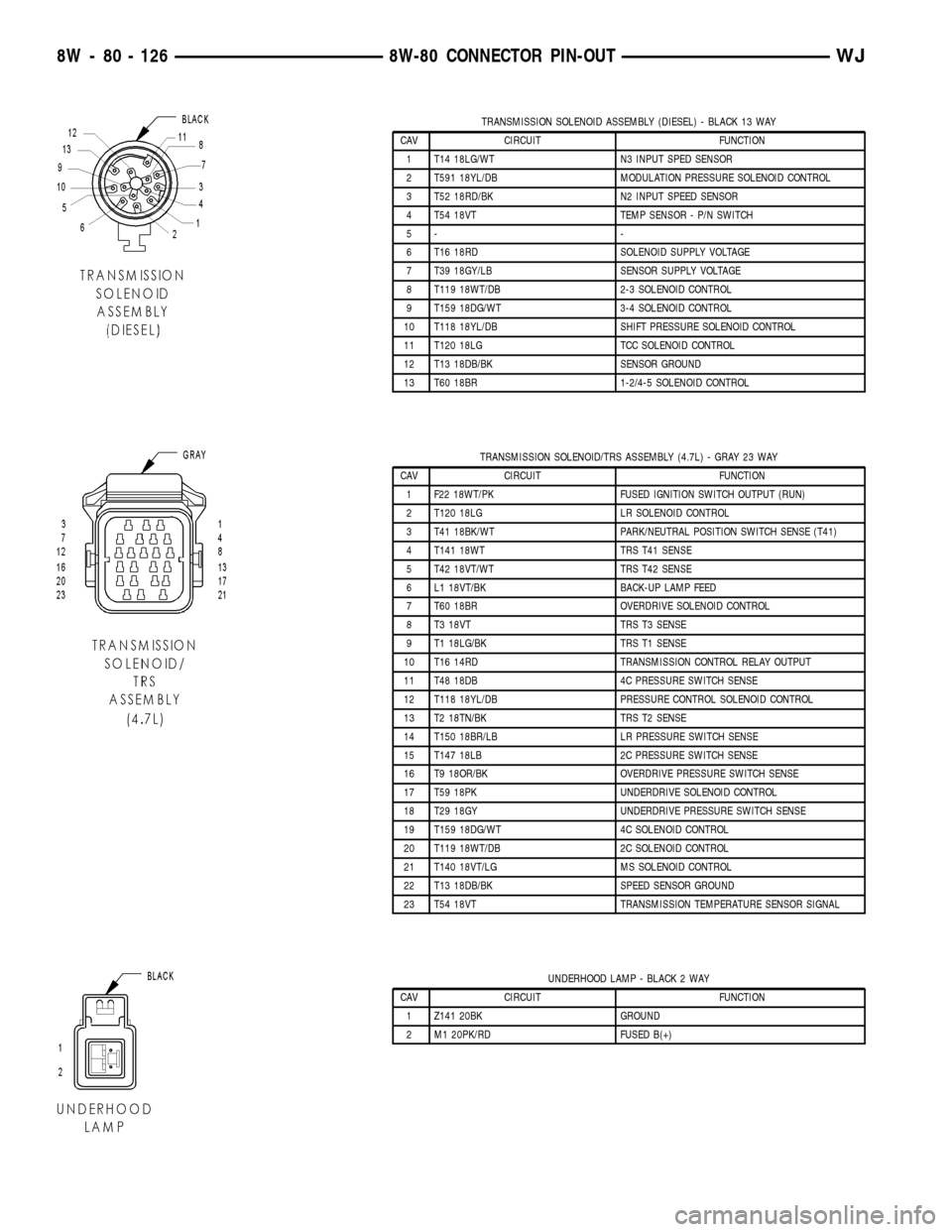
TRANSMISSION SOLENOID ASSEMBLY (DIESEL) - BLACK 13 WAY
CAV CIRCUIT FUNCTION
1 T14 18LG/WT N3 INPUT SPED SENSOR
2 T591 18YL/DB MODULATION PRESSURE SOLENOID CONTROL
3 T52 18RD/BK N2 INPUT SPEED SENSOR
4 T54 18VT TEMP SENSOR - P/N SWITCH
5- -
6 T16 18RD SOLENOID SUPPLY VOLTAGE
7 T39 18GY/LB SENSOR SUPPLY VOLTAGE
8 T119 18WT/DB 2-3 SOLENOID CONTROL
9 T159 18DG/WT 3-4 SOLENOID CONTROL
10 T118 18YL/DB SHIFT PRESSURE SOLENOID CONTROL
11 T120 18LG TCC SOLENOID CONTROL
12 T13 18DB/BK SENSOR GROUND
13 T60 18BR 1-2/4-5 SOLENOID CONTROL
TRANSMISSION SOLENOID/TRS ASSEMBLY (4.7L) - GRAY 23 WAY
CAV CIRCUIT FUNCTION
1 F22 18WT/PK FUSED IGNITION SWITCH OUTPUT (RUN)
2 T120 18LG LR SOLENOID CONTROL
3 T41 18BK/WT PARK/NEUTRAL POSITION SWITCH SENSE (T41)
4 T141 18WT TRS T41 SENSE
5 T42 18VT/WT TRS T42 SENSE
6 L1 18VT/BK BACK-UP LAMP FEED
7 T60 18BR OVERDRIVE SOLENOID CONTROL
8 T3 18VT TRS T3 SENSE
9 T1 18LG/BK TRS T1 SENSE
10 T16 14RD TRANSMISSION CONTROL RELAY OUTPUT
11 T48 18DB 4C PRESSURE SWITCH SENSE
12 T118 18YL/DB PRESSURE CONTROL SOLENOID CONTROL
13 T2 18TN/BK TRS T2 SENSE
14 T150 18BR/LB LR PRESSURE SWITCH SENSE
15 T147 18LB 2C PRESSURE SWITCH SENSE
16 T9 18OR/BK OVERDRIVE PRESSURE SWITCH SENSE
17 T59 18PK UNDERDRIVE SOLENOID CONTROL
18 T29 18GY UNDERDRIVE PRESSURE SWITCH SENSE
19 T159 18DG/WT 4C SOLENOID CONTROL
20 T119 18WT/DB 2C SOLENOID CONTROL
21 T140 18VT/LG MS SOLENOID CONTROL
22 T13 18DB/BK SPEED SENSOR GROUND
23 T54 18VT TRANSMISSION TEMPERATURE SENSOR SIGNAL
UNDERHOOD LAMP - BLACK 2 WAY
CAV CIRCUIT FUNCTION
1 Z141 20BK GROUND
2 M1 20PK/RD FUSED B(+)
8W - 80 - 126 8W-80 CONNECTOR PIN-OUTWJ
Page 1174 of 2199
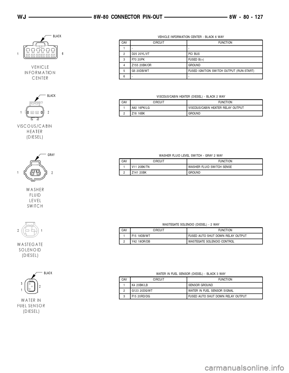
VEHICLE INFORMATION CENTER - BLACK 6 WAY
CAV CIRCUIT FUNCTION
1- -
2 D25 20YL/VT PCI BUS
3 F70 20PK FUSED B(+)
4 Z155 20BK/OR GROUND
5 G5 20DB/WT FUSED IGNITION SWITCH OUTPUT (RUN-START)
6- -
VISCOUS/CABIN HEATER (DIESEL) - BLACK 2 WAY
CAV CIRCUIT FUNCTION
1 A82 16PK/LG VISCOUS/CABIN HEATER RELAY OUTPUT
2 Z18 16BK GROUND
WASHER FLUID LEVEL SWITCH - GRAY 2 WAY
CAV CIRCUIT FUNCTION
1 V11 20BK/TN WASHER FLUID SWITCH SENSE
2 Z141 20BK GROUND
WASTEGATE SOLENOID (DIESEL)-2WAY
CAV CIRCUIT FUNCTION
1 F15 18DB/WT FUSED AUTO SHUT DOWN RELAY OUTPUT
2 Y42 18OR/DB WASTEGATE SOLENOID CONTROL
WATER IN FUEL SENSOR (DIESEL) - BLACK 3 WAY
CAV CIRCUIT FUNCTION
1 K4 20BK/LB SENSOR GROUND
2 G123 20DG/WT WATER IN FUEL SENSOR SIGNAL
3 F15 20RD/DG FUSED AUTO SHUT DOWN RELAY OUTPUT
WJ8W-80 CONNECTOR PIN-OUT 8W - 80 - 127
Page 1181 of 2199
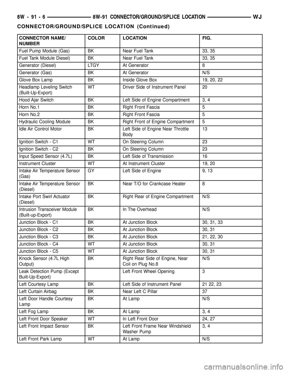
CONNECTOR NAME/
NUMBERCOLOR LOCATION FIG.
Fuel Pump Module (Gas) BK Near Fuel Tank 33, 35
Fuel Tank Module Diesel) BK Near Fuel Tank 33, 35
Generator (Diesel) LTGY At Generator 8
Generator (Gas) BK At Generator N/S
Glove Box Lamp BK Inside Glove Box 19, 20, 22
Headlamp Leveling Switch
(Built-Up-Export)WT Driver Side of Instrument Panel 20
Hood Ajar Switch BK Left Side of Engine Compartment 3, 4
Horn No.1 BK Right Front Fascia 5
Horn No.2 BK Right Front Fascia 5
Hydraulic Cooling Module BK Right Front of Engine Compartment 5
Idle Air Control Motor BK Left Side of Engine Near Throttle
Body13
Ignition Switch - C1 WT On Steering Column 23
Ignition Switch - C2 BK On Steering Column 23
Input Speed Sensor (4.7L) BK Left Side of Transmission 16
Instrument Cluster WT At Instrument Cluster 19, 20
Intake Air Temperature Sensor
(Gas)GY Left Side of Engine 9, 13
Intake Air Temperature Sensor
(Diesel)BK Near T/O for Crankcase Heater 8
Intake Port Swirl Actuator
(Diesel)BK Right Rear of Engine Compartment N/S
Intrusion Transceiver Module
(Built-up-Export)BK In The Overhead N/S
Junction Block - C1 BK At Junction Block 30, 31, 33
Junction Block - C2 BK At Junction Block 30, 31
Junction Block - C3 BK At Junction Block 21, 22, 30
Junction Block - C4 WT At Junction Block 30, 31
Junction Block - C5 WT At Junction Block 30, 31
Knock Sensor (4.7L High
Output)BK Right Rear Side of Engine, Near
Coil on Plug No.8N/S
Leak Detection Pump (Except
Built-Up-Export)Left Front Wheel Opening 3
Left Courtesy Lamp BK Left Side of Instrument Panel 21 22, 23
Left Curtain Airbag BK Near Left C Pillar 37
Left Door Handle Courtesy
LampBK At Lamp N/S
Left Fog Lamp BK At Lamp 3, 4
Left Front Door Speaker WT In Left Front Door 24, 27
Left Front Impact Sensor BK Left Front Frame Near Windshield
Washer Pump3, 4
Left Front Park Lamp WT At Lamp N/S
8W - 91 - 6 8W-91 CONNECTOR/GROUND/SPLICE LOCATIONWJ
CONNECTOR/GROUND/SPLICE LOCATION (Continued)
Page 1227 of 2199

the same time, the power distribution system was
designed to provide ready access to these electrical
distribution points for the vehicle technician to use
when conducting diagnosis and repair of faulty cir-
cuits. The power distribution system can also prove
useful for the sourcing of additional electrical circuits
that may be required to provide the electrical current
needed to operate accessories that the vehicle owner
may choose to have installed in the aftermarket.
NOTE: DO NOT ATTEMPT TO SWAP POWER DIS-
TRIBUTION CENTERS FROM ONE VEHICLE TO
ANOTHER. MOST OF THESE ASSEMBLIES ARE
VEHICLE FEATURE SPECIFIC AND THEREFORE
NOT INTERCHANGEABLE. ALWAYS USE THE COR-
RECT PART NUMBERED ASSEMBLY WHEN DIAG-
NOSING OR REPLACING A POWER DISTRIBUTION
CENTER.
SPECIAL TOOLS
POWER DISTRIBUTION SYSTEMS
CIGAR LIGHTER OUTLET
DESCRIPTION
A cigar lighter outlet is standard equipment on
this model. On models equipped with the optional
Smoker's Package, the cigar lighter knob and heating
element are included. On models without the Smok-
er's Package, the cigar lighter outlet is equipped with
a snap fit plastic cap and is treated as an extra
accessory power outlet. The cigar lighter outlet is
installed in the instrument panel center lower bezel,
which is located near the bottom of the instrument
panel center stack area, below the heater and air
conditioner controls. The cigar lighter outlet is
secured by a snap fit within the center lower bezel.The cigar lighter outlet, plastic cap and the knob
and heating element unit are available for service
replacement. These components cannot be repaired
and, if faulty or damaged, they must be replaced.
OPERATION
The cigar lighter consists of two major components:
a knob and heating element unit, and the cigar
lighter base or outlet shell. The receptacle shell is
connected to ground, and an insulated contact in the
bottom of the shell is connected to battery current.
The cigar lighter receives battery voltage from a fuse
in the junction block when the ignition switch is in
the Accessory or On positions.
The cigar lighter knob and heating element are
encased within a spring-loaded housing, which also
features a sliding protective heat shield. When the
knob and heating element are inserted in the outlet
shell, the heating element resistor coil is grounded
through its housing to the outlet shell. If the cigar
lighter knob is pushed inward, the heat shield slides
up toward the knob exposing the heating element,
and the heating element extends from the housing
toward the insulated contact in the bottom of the
outlet shell.
Two small spring-clip retainers are located on
either side of the insulated contact inside the bottom
of the outlet shell. These clips engage and hold the
heating element against the insulated contact long
enough for the resistor coil to heat up. When the
heating element is engaged with the contact, battery
current can flow through the resistor coil to ground,
causing the resistor coil to heat.
When the resistor coil becomes sufficiently heated,
excess heat radiates from the heating element caus-
ing the spring-clips to expand. Once the spring-clips
expand far enough to release the heating element,
the spring-loaded housing forces the knob and heat-
ing element to pop back outward to their relaxed
position. When the cigar lighter knob and element
are pulled out of the outlet shell, the protective heat
shield slides downward on the housing so that the
heating element is recessed and shielded around its
circumference for safety.
DIAGNOSIS AND TESTING - CIGAR LIGHTER
OUTLET
For complete circuit diagrams, refer toHorn/Ci-
gar Lighter/Power Outletin Wiring Diagrams.
(1) Check the fused B(+) fuse in the junction block.
If OK, go to Step 2. If not OK, repair the shorted cir-
cuit or component as required and replace the faulty
fuse.
(2) Turn the ignition switch to the On position.
Check for battery voltage at the fused B(+) fuse in
Terminal Pick Kit 6680
8W - 97 - 2 8W-97 POWER DISTRIBUTIONWJ
POWER DISTRIBUTION (Continued)
Page 1228 of 2199

the junction block. If OK, go to Step 3. If not OK,
repair the open or short as required.
(3) Remove the cigar lighter knob and element
from the cigar lighter outlet shell. Check for continu-
ity between the inside circumference of the cigar
lighter outlet shell and a good ground. there should
be continuity. If OK, go to Step 4. If not OK, go to
Step 5.
(4) Turn the ignition switch to the On position.
Check for battery voltage at the insulated contact
located at the back of the cigar lighter outlet shell. If
OK, replace the faulty cigar lighter knob and ele-
ment. If not OK, go to Step 5.
(5) Turn the ignition switch to the Off position.
Disconnect and isolate the battery negative cable.
Remove the instrument panel center lower bezel.
Check for continuity between the ground circuit cav-
ity of the cigar lighter wire harness connector and a
good ground. There should be continuity. If OK, go to
Step 6. If not OK, repair the open ground circuit to
ground as required.
(6) Connect the battery negative cable. Turn the
ignition switch to the Accessory or On positions.
Check for battery voltage at the fused B(+) circuit
cavity of the cigar lighter wire harness connector. If
OK, replace the faulty cigar lighter outlet. If not OK,
repair the open fused B(+) circuit to the junction
block fuse as required.
CIGAR LIGHTER OUTLET
DOOR SPRING
REMOVAL
(1) Disconnect and isolate the negative battery
cable.
(2) Remove the instrument panel center lower
bezel from the I.P. Refer to Body for the procedure.
(3) Remove the cigar lighter outlet door spring
from its locating holes (Fig. 1).
INSTALLATION
(1) Install the cigar outlet door spring in its locat-
ing holes.
(2) Install the instrument panel center lower bezel
on the I.P. Refer to Body for the procedure.
(3) Connect the negative battery cable.
IOD FUSE
DESCRIPTION
All vehicles are equipped with an Ignition-Off
Draw (IOD) fuse (Fig. 2) that is removed from its
cavity in the Power Distribution Center (PDC) when
the vehicle is shipped from the factory. Dealer per-sonnel are to remove the IOD fuse from the storage
location and install it into PDC fuse cavity 15 as part
Fig. 1 Cigar Lighter Outlet Door Spring
1 - CIGAR LIGHTER OUTLET
2 - CIGAR LIGHTER OUTLET DOOR SPRING
Fig. 2 Ignition-Off Draw Fuse
1 - POWER DISTRIBUTION CENTER
2 - IGNITION-OFF DRAW FUSE
3 - IOD FUSE STORAGE CAVITY
WJ8W-97 POWER DISTRIBUTION 8W - 97 - 3
CIGAR LIGHTER OUTLET (Continued)
Page 1229 of 2199

of the preparation procedures performed just prior to
new vehicle delivery.
The PDC has a molded plastic cover that can be
removed to provide service access to all of the fuses
and relays in the PDC. An integral latch and hinges
are molded into the PDC cover for easy removal. A
fuse layout map is integral to the underside of the
PDC cover to ensure proper fuse and relay identifica-
tion. The IOD fuse is a 50 ampere maxi-type car-
tridge fuse and, when removed, it is stored in a spare
fuse cavity within the PDC.
OPERATION
The term ignition-off draw identifies a normal con-
dition where power is being drained from the battery
with the ignition switch in the Off position. The IOD
fuse feeds the memory and sleep mode functions for
some of the electronic modules in the vehicle as well
as various other accessories that require battery cur-
rent when the ignition switch is in the Off position,
including the clock. The only reason the IOD fuse is
removed is to reduce the normal IOD of the vehicle
electrical system during new vehicle transportation
and pre-delivery storage to reduce battery depletion,
while still allowing vehicle operation so that the
vehicle can be loaded, unloaded and moved as needed
by both vehicle transportation company and dealer
personnel.
The IOD fuse is removed from PDC fuse cavity 15
when the vehicle is shipped from the assembly plant.
Dealer personnel must install the IOD fuse when the
vehicle is being prepared for delivery in order to
restore full electrical system operation. Once the
vehicle is prepared for delivery, the IOD function of
this fuse becomes transparent and the fuse that has
been assigned the IOD designation becomes only
another Fused B(+) circuit fuse. The IOD fuse serves
no useful purpose to the dealer technician in the ser-
vice or diagnosis of any vehicle system or condition,
other than the same purpose as that of any other
standard circuit protection device.
The IOD fuse can be used by the vehicle owner as
a convenient means of reducing battery depletion
when a vehicle is to be stored for periods not toexceed about thirty days. However, it must be
remembered that removing the IOD fuse will not
eliminate IOD, but only reduce this normal condition.
If a vehicle will be stored for more than about thirty
days, the battery negative cable should be discon-
nected to eliminate normal IOD; and, the battery
should be tested and recharged at regular intervals
during the vehicle storage period to prevent the bat-
tery from becoming discharged or damaged. Refer to
Battery Systemfor additional service information.
REMOVAL
The Ignition-Off Draw (IOD) fuses normal installa-
tion location is cavity 15 in the power distribution
center. When the vehicle is shipped from the assem-
bly plant the fuse is removed to maintain proper bat-
tery voltage during vehicle storage (in some cases).
Dealer personnel must install the IOD fuse when the
vehicle is being prepared for customer delivery in
order to restore full electrical system operation.
(1) Turn the ignition switch to the Off position.
(2) Unlatch and open the cover of the power distri-
bution center.
(3) Remove the IOD fuse from fusecavity 15of
the power distribution center (Fig. 2).
(4) Store the removed IOD fuse by installing it in
the unused fuse storagecavity 11of the PDC (Fig.
2).
(5) Close and latch the power distribution center
cover.
INSTALLATION
(1) Be certain the ignition switch is in the Off posi-
tion.
(2) Unlatch and open the cover of the power distri-
bution center.
(3) Remove the stored IOD fuse from fuse storage
cavity 11of the power distribution center.
(4) Use a thumb to press the IOD fuse firmly down
into power distribution center fusecavity 15.
(5) Close and latch the power distribution center
cover.
8W - 97 - 4 8W-97 POWER DISTRIBUTIONWJ
IOD FUSE (Continued)