2002 JEEP GRAND CHEROKEE Fuel injector harness
[x] Cancel search: Fuel injector harnessPage 321 of 2199

INSTALLATION
(1) Install the MHSM,HSM into the bracket.
(2) Position the heated seat module and mounting
bracket onto the power seat track.
(3) Reconnect the power seat wiring harness con-
nectors to the heated seat module.
(4) Install the driver side front bucket seat onto
the power seat track unit (Refer to 23 - BODY/
SEATS/SEAT TRACK ADJUSTER - INSTALLA-
TION).
(5) Reconnect the battery negative cable.
NOTE: If the vehicle is equipped with the optional
Memory System, following installation, it will be
necessary to initialize the Memory Heated Seat
Module (MHSM). In order to function properly, the
MHSM must ªlearnº the sensor values of each of
the power seat motor position transducers in each
of the adjuster hard stop positions. This is done by
performing the ªReset Guard Bandº procedure
using a DRBIIITscan tool and the proper Diagnostic
Procedures manual.
WARNING: THE ªRESET GUARD BANDº PROCE-
DURE WILL CAUSE THE DRIVER SIDE FRONT
SEAT TO AUTOMATICALLY ADJUST TO EACH OF
ITS TRAVEL LIMITS. BE CERTAIN THAT NO ONE IS
SEATED IN THE VEHICLE AND THAT THERE IS
NOTHING IN THE VEHICLE THAT WILL OBSTRUCT
SEAT MOVEMENT. FAILURE TO OBSERVE THIS
WARNING COULD RESULT IN PERSONAL INJURIES
AND/OR VEHICLE DAMAGE.
POWERTRAIN CONTROL
MODULE
DESCRIPTION
DESCRIPTION - PCM
The Powertrain Control Module (PCM) is located
in the engine compartment (Fig. 11). The PCM is
referred to as JTEC.
MODES OF OPERATION
As input signals to the Powertrain Control Module
(PCM) change, the PCM adjusts its response to the
output devices. For example, the PCM must calculate
different injector pulse width and ignition timing for
idle than it does for wide open throttle (WOT).
The PCM will operate in two different modes:
Open Loop and Closed Loop.
During Open Loop modes, the PCM receives input
signals and responds only according to preset PCMprogramming. Input from the oxygen (O2S) sensors
is not monitored during Open Loop modes.
During Closed Loop modes, the PCM will monitor
the oxygen (O2S) sensors input. This input indicates
to the PCM whether or not the calculated injector
pulse width results in the ideal air-fuel ratio. This
ratio is 14.7 parts air-to-1 part fuel. By monitoring
the exhaust oxygen content through the O2S sensor,
the PCM can fine tune the injector pulse width. This
is done to achieve optimum fuel economy combined
with low emission engine performance.
The fuel injection system has the following modes
of operation:
²Ignition switch ON
²Engine start-up (crank)
²Engine warm-up
²Idle
²Cruise
²Acceleration
²Deceleration
²Wide open throttle (WOT)
²Ignition switch OFF
The ignition switch On, engine start-up (crank),
engine warm-up, acceleration, deceleration and wide
open throttle modes are Open Loop modes. The idle
and cruise modes, (with the engine at operating tem-
perature) are Closed Loop modes.
IGNITION SWITCH (KEY-ON) MODE
This is an Open Loop mode. When the fuel system
is activated by the ignition switch, the following
actions occur:
Fig. 11 PCM Location
1 - PCM
2 - COOLANT TANK
8E - 12 ELECTRONIC CONTROL MODULESWJ
MEMORY HEATED SEAT/MIRROR MODULE (Continued)
Page 1255 of 2199

(7) Remove the fan assembly from the water pump
(Refer to 7 - COOLING/ENGINE/RADIATOR FAN -
REMOVAL).
(8) Remove the fan shroud.
(9) Disconnect the transmission fluid cooler lines
(automatic transmission).
(10) Discharge the A/C system (Refer to 24 -
HEATING & AIR CONDITIONING/PLUMBING -
STANDARD PROCEDURE).
(11) Remove the service valves and cap the com-
pressor ports.
(12) Remove the radiator or radiator/condenser (if
equipped with A/C).
(13) Disconnect the heater hoses at the engine
thermostat housing and water pump.
(14) Disconnect the accelerator cable, transmission
line pressure cable and speed control cable (if
equipped) from the throttle body.
(15) Remove cables from the bracket and secure
out of the way.
(16) Disconnect the body ground at the engine.
(17) Disconnect the following connectors and
secure their harness out of the way.
²Power steering pressure switch
²Coolant temperature sensor
²Six (6) fuel injector connectors
²Intake air temperature sensor
²Throttle position sensor
²Map sensor
²Crankshaft position sensor
²Oxygen sensor
²Camshaft position sensor
²Generator connector and B+ terminal wire
(18) Disconnect the coil rail electrical connections
and the oil pressure switch connector.
(19) Perform the fuel pressure release procedure
(Refer to 14 - FUEL SYSTEM/FUEL DELIVERY -
STANDARD PROCEDURE).
(20) Disconnect the fuel supply line at the injector
rail (Refer to 14 - FUEL SYSTEM/FUEL DELIVERY/
QUICK CONNECT FITTING - STANDARD PROCE-
DURE).
(21) Remove the fuel line bracket from the intake
manifold.
(22) Remove the air cleaner assembly (Fig. 5).
(23) Disconnect the hoses from the fittings at the
steering gear.
(24) Drain the pump reservoir.
(25) Cap the fittings on the hoses and steering
gear to prevent foreign objects from entering the sys-
tem.
(26) Raise and support the vehicle.
(27) Disconnect the wires from the engine starter
motor solenoid.(28) Remove the engine starter motor (Refer to 8 -
ELECTRICAL/STARTING/STARTER MOTOR -
REMOVAL).
(29) Disconnect the oxygen sensor from the
exhaust pipe.
(30) Disconnect the exhaust pipe from the mani-
fold.
(31) Remove the exhaust pipe support.
(32) Remove the bending brace (Refer to 9 -
ENGINE/ENGINE BLOCK/STRUCT SUPPORT -
REMOVAL).
(33) Remove the engine flywheel/converter housing
access cover.
(34) Mark the converter and drive plate location.
(35) Remove the converter-to-drive plate bolts.
(36) Remove the upper engine flywheel/converter
housing bolts and loosen the bottom bolts.
(37) Remove the engine mount cushion-to-engine
compartment bracket bolts.
(38) Lower the vehicle.
(39) Attach a lifting device to the engine.
(40) Raise the engine off the front supports.
(41) Place a support or floor jack under the con-
verter (or engine flywheel) housing.
(42) Remove the remaining converter (or engine
flywheel) housing bolts.
(43) Lift the engine out of the engine compart-
ment.
Fig. 5 Air Cleaner Assembly
1 - POWER STEERING PUMP
2 - AIR CLEANER ASSEMBLY
9 - 12 ENGINE - 4.0LWJ
ENGINE - 4.0L (Continued)
Page 1300 of 2199

INSTALLATION
A gear-type oil pump is mounted at the underside
of the cylinder block opposite the No.4 main bearing.
(1) Install the oil pump on the cylinder block using
a replacement gasket. Tighten the bolts to 23 N´m
(17 ft. lbs.) torque.
(2) Install the oil pan (Refer to 9 - ENGINE/LU-
BRICATION/OIL PAN - INSTALLATION).
(3) Fill the oil pan with oil to the specified level.
INTAKE MANIFOLD
DESCRIPTION
The intake manifold (Fig. 83) is made of cast alu-
minum and uses eleven bolts to mount to the cylin-
der head. This mounting style improves sealing and
reduces the chance of leaks.
DIAGNOSIS AND TESTING - INTAKE
MANIFOLD LEAKAGE
An intake manifold air leak is characterized by
lower than normal manifold vacuum. Also, one or
more cylinders may not be functioning.
WARNING: USE EXTREME CAUTION WHEN THE
ENGINE IS OPERATING. DO NOT STAND IN A
DIRECT LINE WITH THE FAN. DO NOT PUT YOUR
HANDS NEAR THE PULLEYS, BELTS OR THE FAN.
DO NOT WEAR LOOSE CLOTHING.
(1) Start the engine.
(2) Spray a small stream of water at the suspected
leak area.
(3) If a change in RPM is observed the area of the
suspected leak has been found.
(4) Repair as required.
REMOVAL
NOTE: THE ENGINE INTAKE AND EXHAUST MANI-
FOLD MUST BE REMOVED AND INSTALLED
TOGETHER. THE MANIFOLDS USE A COMMON
GASKET AT THE CYLINDER HEAD.
(1) Disconnect the battery negative cable.
(2) Remove air cleaner inlet hose from the resona-
tor assembly.
(3) Remove the air cleaner assembly.
(4) Remove the throttle cable, vehicle speed control
cable (if equipped) and the transmission line pres-
sure cable (Refer to 21 - TRANSMISSION/TRANS-
AXLE/AUTOMATIC - AW4/THROTTLE VALVE
CABLE - REMOVAL).
(5) Disconnect the following electrical connections
and secure their harness out of the way:
²Throttle Position Sensor
²Idle Air Control Motor
²Coolant Temperature Sensor (at thermostat
housing)
²Intake Air Temperature Sensor
²Oxygen Sensor
²Crank Position Sensor
²Six (6) Fuel Injector Connectors
²Manifold Absolute Pressure (MAP) Sensor.
(6) Disconnect HVAC, and Brake Booster vacuum
supply hoses at the intake manifold.
(7) Perform the fuel pressure release procedure.
(Refer to 14 - FUEL SYSTEM/FUEL DELIVERY -
STANDARD PROCEDURE).
(8) Disconnect and remove the fuel system supply
line from the fuel rail assembly.
(9) Remove the accessory drive belt (Refer to 7 -
COOLING/ACCESSORY DRIVE/DRIVE BELTS -
REMOVAL).
(10) Remove the power steering pump from the
intake manifold and set aside.
(11) Raise the vehicle.
(12) Disconnect the exhaust pipes from the engine
exhaust manifolds.
(13) Lower the vehicle.
(14) Remove the intake manifold and exhaust
manifold bolts and manifolds (Fig. 84).
INSTALLATION
If the manifold is being replaced, ensure all the fit-
ting, etc. are transferred to the replacement mani-
fold.
(1) Install a new engine exhaust/intake manifold
gasket over the alignment dowels on the cylinder
head.
(2) Position the engine exhaust manifolds to the
cylinder head. Install fastener Number 3 and finger
tighten at this time (Fig. 84).
Fig. 83 Intake Manifold 4.0L Engine
WJENGINE - 4.0L 9 - 57
OIL PUMP (Continued)
Page 1315 of 2199

(13) Disconnect the engine block heater power
cable from the block heater.
(14) Lower vehicle.
(15) Remove throttle body resonator assembly and
inlet hose.
(16) Disconnect throttle and speed control cables.
(17) Disconnect tube from both the left and right
side crankcase breathers, then remove the breathers
(Fig. 5).
(18) Discharge A/C system (Refer to 24 - HEAT-
ING & AIR CONDITIONING/PLUMBING - STAN-
DARD PROCEDURE).(19) Remove radiator fan (Refer to 7 - COOLING/
ENGINE/RADIATOR FAN - REMOVAL) and acces-
sory drive belt (Refer to 7 - COOLING/ACCESSORY
DRIVE/DRIVE BELTS - REMOVAL).
(20) Remove A/C compressor (Refer to 24 - HEAT-
ING & AIR CONDITIONING/PLUMBING/A/C COM-
PRESSOR - REMOVAL).
(21) Disconnect transmission oil cooler lines at the
radiator.
(22) Disconnect radiator lower hose at the thermo-
stat housing.
(23) Remove A/C condenser (Refer to 24 - HEAT-
ING & AIR CONDITIONING/PLUMBING/A/C CON-
DENSER - REMOVAL).
(24) Remove radiator (Refer to 7 - COOLING/EN-
GINE/RADIATOR - REMOVAL).
(25) Remove generator (Refer to 8 - ELECTRICAL/
CHARGING/GENERATOR - REMOVAL).
(26) Disconnect the two heater hoses from the tim-
ing chain cover.
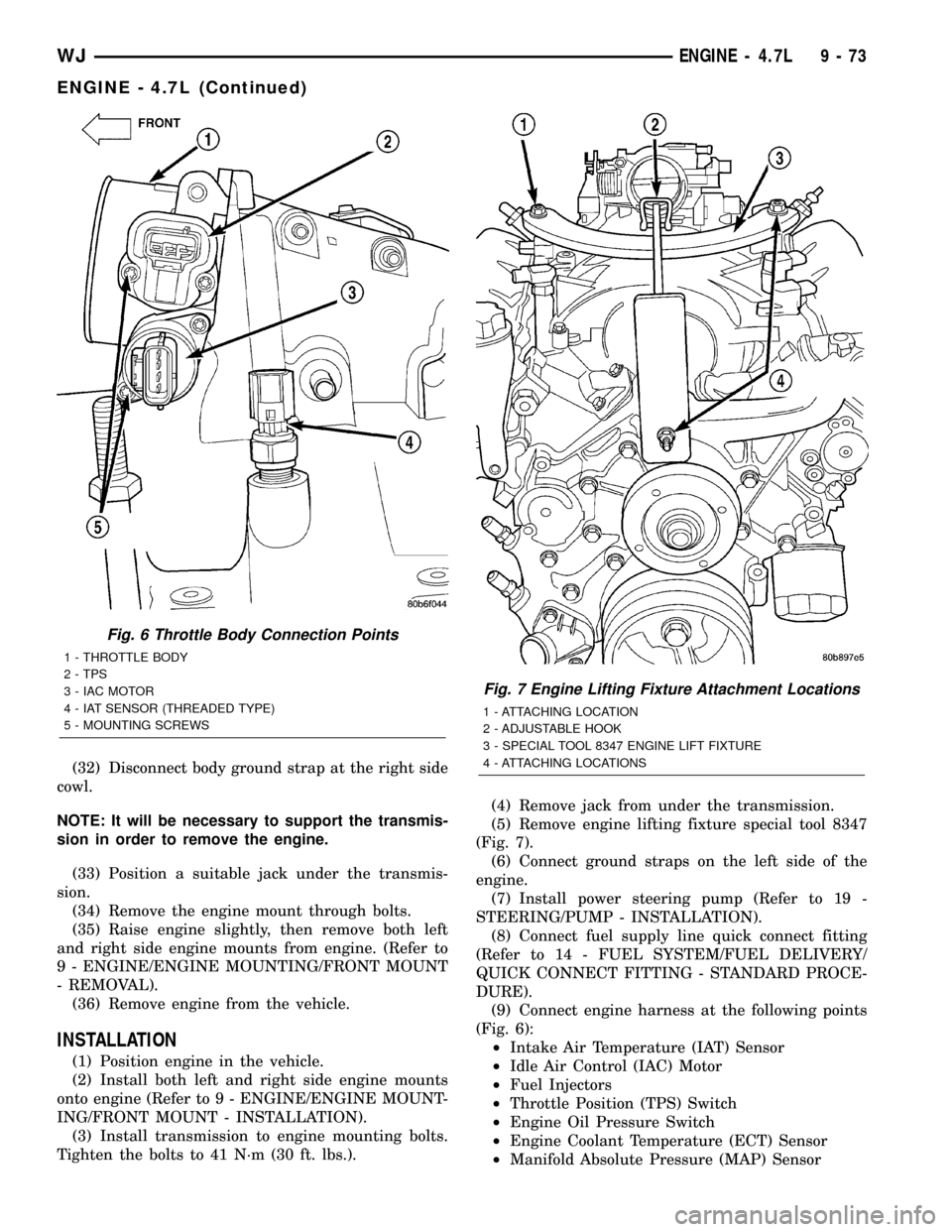
(27) Disconnect engine harness at the following
points :
²Intake air temperature (IAT) sensor (Fig. 6)
²Fuel Injectors
²Throttle Position (TPS) Switch
²Idle Air Control (IAC) Motor
²Engine Oil Pressure Switch
²Engine Coolant Temperature (ECT) Sensor
²Manifold absolute pressure (MAP) Sensor
²Camshaft Position (CMP) Sensor
²Coil Over Plugs
(28) Release fuel rail pressure (Refer to 14 - FUEL
SYSTEM/FUEL DELIVERY - STANDARD PROCE-
DURE) then disconnect the fuel supply quick connect
fitting at the fuel rail (Refer to 14 - FUEL SYSTEM/
FUEL DELIVERY/QUICK CONNECT FITTING -
STANDARD PROCEDURE).
(29) Remove power steering pump and position out
of the way.
(30) Disconnect ground straps from the left side of
the engine.
(31) Install Engine Lifting Fixture Special Tool
8347 (Fig. 7)following these steps.
²Holding the lifting fixture at a slight angle, slide
the large bore in the front plate over the hex portion
of the lifting stud.
²Position the two remaining fixture arms onto
the two lifting studs in the cylinder heads.
²Pull foward and upward on the lifting fixture so
that the lifting stud rest in the slotted area below the
large bore.
²Secure the lifting fixture to the three studs
using three 7/16 ± 14 N/C locknuts.
²Make sure the lifting loop in the lifting fixture is
in the last hole (closest to the throttle body) to min-
imize the angle of engine during removal.
Fig. 4 Crankshaft Position Sensor
1 - CRANKSHAFT POSITION SENSOR
2 - CYLINDER HEAD COVER
3 - CAMSHAFT POSITION SENSOR
4 - RIGHT SIDE CYLINDER BLOCK
Fig. 5 Crankcase Breather Connection Points
1 - CRANKCASE BREATHERS
9 - 72 ENGINE - 4.7LWJ
ENGINE - 4.7L (Continued)
Page 1316 of 2199

(32) Disconnect body ground strap at the right side
cowl.
NOTE: It will be necessary to support the transmis-
sion in order to remove the engine.
(33) Position a suitable jack under the transmis-
sion.
(34) Remove the engine mount through bolts.
(35) Raise engine slightly, then remove both left
and right side engine mounts from engine. (Refer to
9 - ENGINE/ENGINE MOUNTING/FRONT MOUNT
- REMOVAL).
(36) Remove engine from the vehicle.
INSTALLATION
(1) Position engine in the vehicle.
(2) Install both left and right side engine mounts
onto engine (Refer to 9 - ENGINE/ENGINE MOUNT-
ING/FRONT MOUNT - INSTALLATION).
(3) Install transmission to engine mounting bolts.
Tighten the bolts to 41 N´m (30 ft. lbs.).(4) Remove jack from under the transmission.
(5) Remove engine lifting fixture special tool 8347
(Fig. 7).
(6) Connect ground straps on the left side of the
engine.
(7) Install power steering pump (Refer to 19 -
STEERING/PUMP - INSTALLATION).
(8) Connect fuel supply line quick connect fitting
(Refer to 14 - FUEL SYSTEM/FUEL DELIVERY/
QUICK CONNECT FITTING - STANDARD PROCE-
DURE).
(9) Connect engine harness at the following points
(Fig. 6):
²Intake Air Temperature (IAT) Sensor
²Idle Air Control (IAC) Motor
²Fuel Injectors
²Throttle Position (TPS) Switch
²Engine Oil Pressure Switch
²Engine Coolant Temperature (ECT) Sensor
²Manifold Absolute Pressure (MAP) Sensor
Fig. 6 Throttle Body Connection Points
1 - THROTTLE BODY
2 - TPS
3 - IAC MOTOR
4 - IAT SENSOR (THREADED TYPE)
5 - MOUNTING SCREWS
Fig. 7 Engine Lifting Fixture Attachment Locations
1 - ATTACHING LOCATION
2 - ADJUSTABLE HOOK
3 - SPECIAL TOOL 8347 ENGINE LIFT FIXTURE
4 - ATTACHING LOCATIONS
WJENGINE - 4.7L 9 - 73
ENGINE - 4.7L (Continued)
Page 1435 of 2199

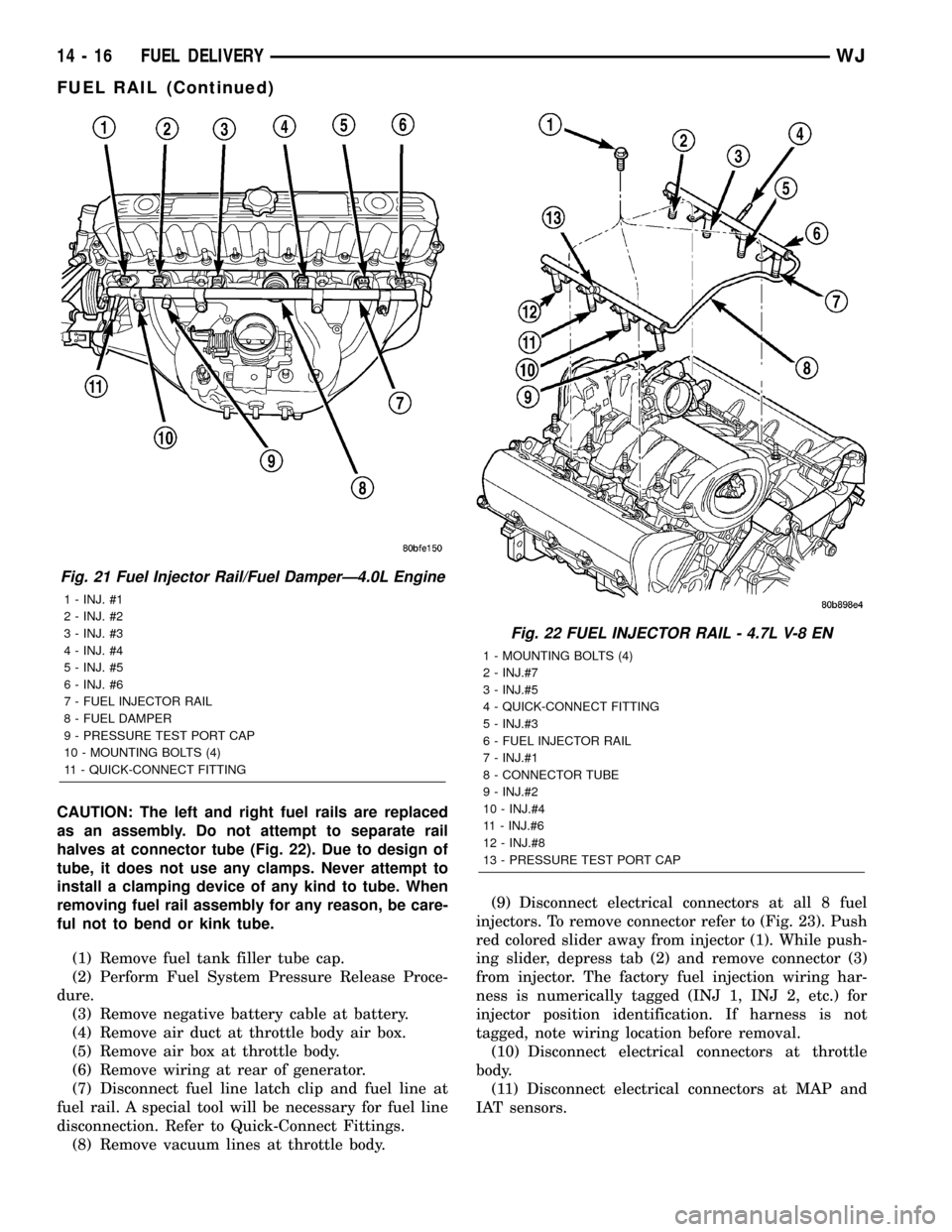
CAUTION: The left and right fuel rails are replaced
as an assembly. Do not attempt to separate rail
halves at connector tube (Fig. 22). Due to design of
tube, it does not use any clamps. Never attempt to
install a clamping device of any kind to tube. When
removing fuel rail assembly for any reason, be care-
ful not to bend or kink tube.
(1) Remove fuel tank filler tube cap.
(2) Perform Fuel System Pressure Release Proce-
dure.
(3) Remove negative battery cable at battery.
(4) Remove air duct at throttle body air box.
(5) Remove air box at throttle body.
(6) Remove wiring at rear of generator.
(7) Disconnect fuel line latch clip and fuel line at
fuel rail. A special tool will be necessary for fuel line
disconnection. Refer to Quick-Connect Fittings.
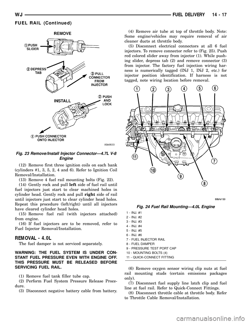
(8) Remove vacuum lines at throttle body.(9) Disconnect electrical connectors at all 8 fuel
injectors. To remove connector refer to (Fig. 23). Push
red colored slider away from injector (1). While push-
ing slider, depress tab (2) and remove connector (3)
from injector. The factory fuel injection wiring har-
ness is numerically tagged (INJ 1, INJ 2, etc.) for
injector position identification. If harness is not
tagged, note wiring location before removal.
(10) Disconnect electrical connectors at throttle
body.
(11) Disconnect electrical connectors at MAP and
IAT sensors.
Fig. 21 Fuel Injector Rail/Fuel DamperÐ4.0L Engine
1 - INJ. #1
2 - INJ. #2
3 - INJ. #3
4 - INJ. #4
5 - INJ. #5
6 - INJ. #6
7 - FUEL INJECTOR RAIL
8 - FUEL DAMPER
9 - PRESSURE TEST PORT CAP
10 - MOUNTING BOLTS (4)
11 - QUICK-CONNECT FITTING
Fig. 22 FUEL INJECTOR RAIL - 4.7L V-8 EN
1 - MOUNTING BOLTS (4)
2 - INJ.#7
3 - INJ.#5
4 - QUICK-CONNECT FITTING
5 - INJ.#3
6 - FUEL INJECTOR RAIL
7 - INJ.#1
8 - CONNECTOR TUBE
9 - INJ.#2
10 - INJ.#4
11 - INJ.#6
12 - INJ.#8
13 - PRESSURE TEST PORT CAP
14 - 16 FUEL DELIVERYWJ
FUEL RAIL (Continued)
Page 1436 of 2199

(12) Remove first three ignition coils on each bank
(cylinders #1, 3, 5, 2, 4 and 6). Refer to Ignition Coil
Removal/Installation.
(13) Remove 4 fuel rail mounting bolts (Fig. 22).
(14) Gently rock and pullleftside of fuel rail until
fuel injectors just start to clear machined holes in
cylinder head. Gently rock and pullrightside of rail
until injectors just start to clear cylinder head holes.
Repeat this procedure (left/right) until all injectors
have cleared cylinder head holes.
(15) Remove fuel rail (with injectors attached)
from engine.
(16) If fuel injectors are to be removed, refer to
Fuel Injector Removal/Installation.
REMOVAL - 4.0L
The fuel damper is not serviced separately.
WARNING: THE FUEL SYSTEM IS UNDER CON-
STANT FUEL PRESSURE EVEN WITH ENGINE OFF.
THIS PRESSURE MUST BE RELEASED BEFORE
SERVICING FUEL RAIL.
(1) Remove fuel tank filler tube cap.
(2) Perform Fuel System Pressure Release Proce-
dure.
(3) Disconnect negative battery cable from battery.(4) Remove air tube at top of throttle body. Note:
Some engine/vehicles may require removal of air
cleaner ducts at throttle body.
(5) Disconnect electrical connectors at all 6 fuel
injectors. To remove connector refer to (Fig. 25). Push
red colored slider away from injector (1). While push-
ing slider, depress tab (2) and remove connector (3)
from injector. The factory fuel injection wiring har-
ness is numerically tagged (INJ 1, INJ 2, etc.) for
injector position identification. If harness is not
tagged, note wiring location before removal.
(6) Remove oxygen sensor wiring clip nuts at fuel
rail mounting studs (certain emissions packages
only).
(7) Disconnect fuel supply line latch clip and fuel
line at fuel rail. Refer to Quick-Connect Fittings.
(8) Disconnect throttle cable at throttle body. Refer
to Throttle Cable Removal/Installation.
Fig. 23 Remove/Install Injector ConnectorÐ4.7L V-8
Engine
Fig. 24 Fuel Rail MountingÐ4.0L Engine
1 - INJ. #1
2 - INJ. #2
3 - INJ. #3
4 - INJ. #4
5 - INJ. #5
6 - INJ. #6
7 - FUEL INJECTOR RAIL
8 - FUEL DAMPER
9 - PRESSURE TEST PORT CAP
10 - MOUNTING BOLTS (4)
11 - QUICK-CONNECT FITTING
WJFUEL DELIVERY 14 - 17
FUEL RAIL (Continued)
Page 1454 of 2199

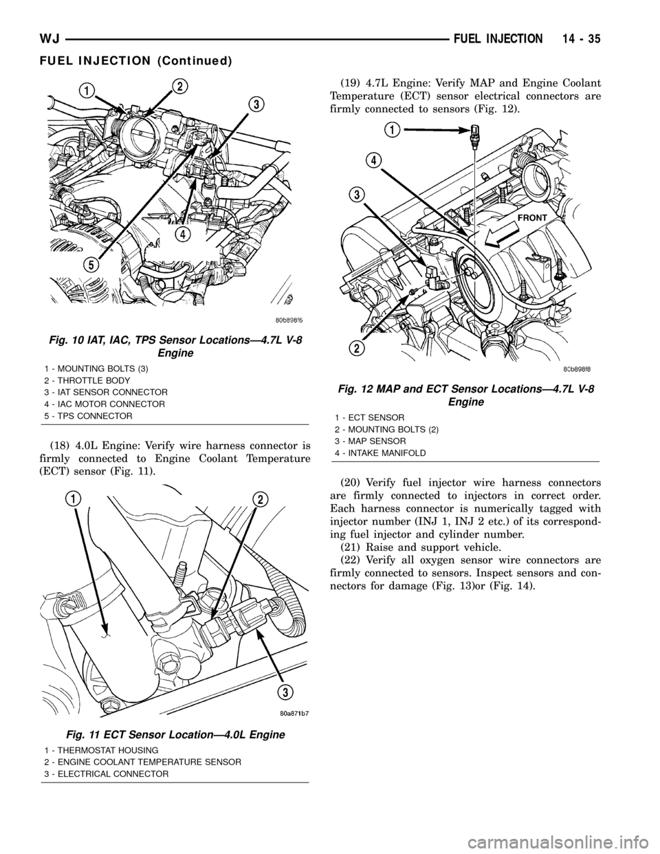
(18) 4.0L Engine: Verify wire harness connector is
firmly connected to Engine Coolant Temperature
(ECT) sensor (Fig. 11).(19) 4.7L Engine: Verify MAP and Engine Coolant
Temperature (ECT) sensor electrical connectors are
firmly connected to sensors (Fig. 12).
(20) Verify fuel injector wire harness connectors
are firmly connected to injectors in correct order.
Each harness connector is numerically tagged with
injector number (INJ 1, INJ 2 etc.) of its correspond-
ing fuel injector and cylinder number.
(21) Raise and support vehicle.
(22) Verify all oxygen sensor wire connectors are
firmly connected to sensors. Inspect sensors and con-
nectors for damage (Fig. 13)or (Fig. 14).
Fig. 10 IAT, IAC, TPS Sensor LocationsÐ4.7L V-8
Engine
1 - MOUNTING BOLTS (3)
2 - THROTTLE BODY
3 - IAT SENSOR CONNECTOR
4 - IAC MOTOR CONNECTOR
5 - TPS CONNECTOR
Fig. 11 ECT Sensor LocationÐ4.0L Engine
1 - THERMOSTAT HOUSING
2 - ENGINE COOLANT TEMPERATURE SENSOR
3 - ELECTRICAL CONNECTOR
Fig. 12 MAP and ECT Sensor LocationsÐ4.7L V-8
Engine
1 - ECT SENSOR
2 - MOUNTING BOLTS (2)
3 - MAP SENSOR
4 - INTAKE MANIFOLD
WJFUEL INJECTION 14 - 35
FUEL INJECTION (Continued)