2002 JEEP GRAND CHEROKEE front upper control arm
[x] Cancel search: front upper control armPage 625 of 2199

(9) Install the six plastic nuts that secure the cowl
grille cover to the studs on the cowl top panel near
the base of the windshield. These nuts are to be
installed by pushing them onto the studs in the fol-
lowing sequence:
(a) First, install the short nuts to the third stud
from the right, then the second stud from the left.
(b) Next, install long nuts to the right outboard
stud, then the left outboard stud.
(c) Finally, install the two remaining long nuts
to the third stud from the left, then the second
stud from the right.
(10) Starting at the ends and working toward the
center, push the hood to plenum seal onto the for-
ward flanges of the cowl grille cover and the plenum
panel.
(11) Close and latch the hood.
(12) Reinstall the wiper arms onto the wiper piv-
ots. (Refer to 8 - ELECTRICAL/FRONT WIPERS/
WASHERS/FRONT WIPER ARMS -
INSTALLATION).
(13) Reconnect the battery negative cable.
RAIN SENSOR MODULE
DESCRIPTION
The Rain Sensor Module (RSM) is the primary
component of the automatic wiper system (Fig. 14).
The RSM is located on the inside of the windshield,
between the rear view mirror mounting button and
the windshield header and is concealed behind a
molded plastic trim cover that snaps over the modulehousing. The triangular-shaped molded black plastic
housing of the RSM has a rectangular opening
located on the upper end of the housing for the mod-
ule connector receptacle, which contains four termi-
nal pins. These terminal pins connect the rain sensor
to the vehicle electrical system through a dedicated
take out and connector of the overhead wire harness
that extends from above the headliner. Five openings
on the windshield side of the RSM housing are fitted
with eight convex clear plastic lenses. A metal spring
clip on each side of the housing near the bottom
secures the RSM to a plastic mounting bracket that
is bonded to the windshield glass. Concealed within
the RSM housing is the electronic circuitry of the
module, which includes four InfraRed (IR) diodes,
two photocells, and a microprocessor.
The RSM software is Flash compatible, which
means it can be reprogrammed using Flash repro-
gramming procedures. However, if any of the hard-
ware of the RSM is damaged or faulty, the entire
module must be replaced. The RSM bracket is ser-
viced as a unit with the windshield glass. If the
bracket is faulty, damaged, or separated from the
windshield glass, the windshield unit must be
replaced.
OPERATION
The microprocessor-based Rain Sensor Module
(RSM) senses moisture in the wipe pattern on the
outside of the windshield glass and sends wipe com-
mands to the Body Control Module (BCM). Four
InfraRed (IR) diodes within the RSM generate IR
light beams that are aimed by four of the convex
optical lenses near the base of the module through
the windshield glass. Four additional convex optical
lenses near the top of the RSM are focused on the IR
light beams on the outside of the windshield glass
and allow the two photocells within the module to
sense changes in the intensity of these IR light
beams. When sufficient moisture accumulates within
the wipe pattern of the windshield glass, the RSM
detects a change in the monitored IR light beam
intensity.
The internal programming of the RSM then sends
the appropriate electronic wipe command messages
to the BCM over the Programmable Communications
Interface (PCI) data bus. The BCM responds by acti-
vating or deactivating the front wiper system. The
BCM also sends electronic sensitivity level messages
to the RSM over the PCI data bus based upon the
driver-selected sensitivity setting of the control knob
on the control stalk of the right (wiper) multi-func-
tion switch. The higher the selected sensitivity set-
ting the more sensitive the RSM is to the
accumulated moisture on the windshield glass, and
Fig. 14 Rain Sensor Module
1 - SPRING CLIP (2)
2 - INFRARED LENS (4)
3 - HOUSING
4 - CONNECTOR RECEPTACLE
5 - PHOTOCELL LENS (4)
8R - 18 FRONT WIPERS/WASHERSWJ
FRONT WIPER MODULE (Continued)
Page 1474 of 2199

REMOVAL - 4.7L
CAUTION: Be careful not to damage or kink the
cable core wire (within the cable sheathing) while
servicing accelerator pedal or throttle cable.
(1) From inside vehicle, hold up accelerator pedal.
Remove plastic cable retainer (clip) and throttle cable
core wire from upper end of pedal arm (Fig. 16).
Plastic cable retainer (clip) snaps into pedal arm.
(2) Remove cable core wire at pedal arm.
(3) From inside vehicle, remove clip holding cable
to dashpanel (Fig. 16).
(4) Remove air box at throttle body.
(5) Unsnap cable from plenum routing clip.
(6) Remove cable housing from dash panel and
pull into engine compartment.
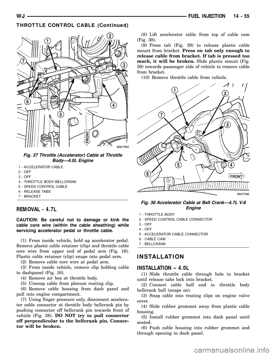
(7) Using finger pressure only, disconnect accelera-
tor cable connector at throttle body bellcrank pin by
pushing connector off bellcrank pin towards front of
vehicle (Fig. 38).DO NOT try to pull connector
off perpendicular to the bellcrank pin. Connec-
tor will be broken.(8) Lift accelerator cable from top of cable cam
(Fig. 38).
(9) Press tab (Fig. 39) to release plastic cable
mount from bracket.Press on tab only enough to
release cable from bracket. If tab is pressed too
much, it will be broken.Slide plastic mount (Fig.
39) towards passenger side of vehicle to remove cable
from bracket.
(10) Remove throttle cable from vehicle.
INSTALLATION
INSTALLATION ± 4.0L
(1) Slide throttle cable through hole in bracket
until release tabs lock into bracket.
(2) Connect cable ball end to throttle body
bellcrank ball (snaps on).
(3) Snap cable into routing clips on engine valve
cover.
(4) Slide rubber grommet away from plastic cable
housing.
(5) Install rubber grommet into dash panel until
seated.
(6) Push cable housing into rubber grommet and
through opening in dash panel.
Fig. 37 Throttle (Accelerator) Cable at Throttle
BodyÐ4.0L Engine
1 - ACCELERATOR CABLE
2 - OFF
3 - OFF
4 - THROTTLE BODY BELLCRANK
5 - SPEED CONTROL CABLE
6 - RELEASE TABS
7 - BRACKET
Fig. 38 Accelerator Cable at Bell CrankÐ4.7L V-8
Engine
1 - THROTTLE BODY
2 - SPEED CONTROL CABLE CONNECTOR
3 - OFF
4 - OFF
5 - ACCELERATOR CABLE CONNECTOR
6 - CABLE CAM
7 - BELLCRANK
WJFUEL INJECTION 14 - 55
THROTTLE CONTROL CABLE (Continued)
Page 2026 of 2199

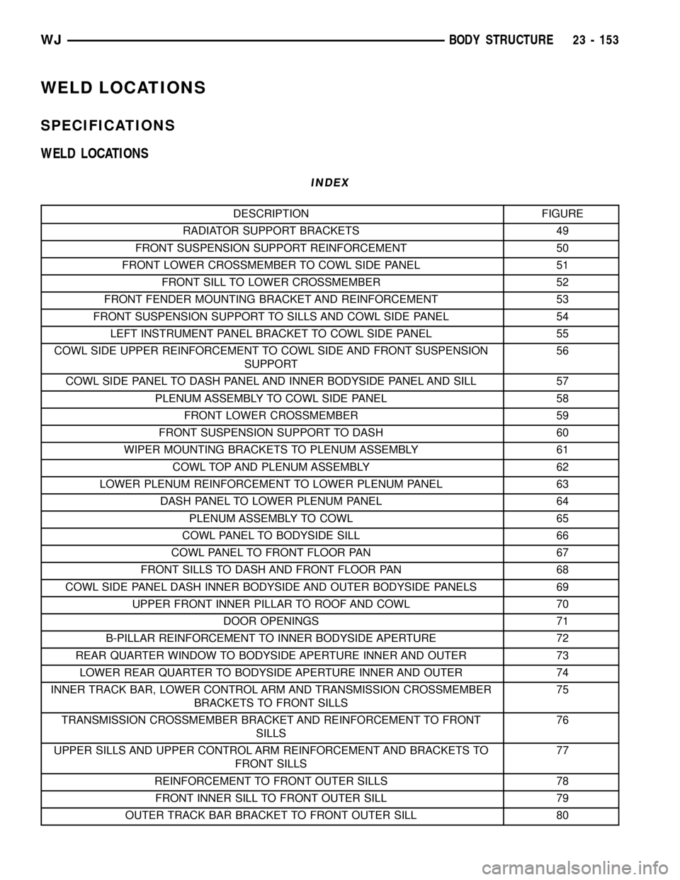
WELD LOCATIONS
SPECIFICATIONS
WELD LOCATIONS
INDEX
DESCRIPTION FIGURE
RADIATOR SUPPORT BRACKETS 49
FRONT SUSPENSION SUPPORT REINFORCEMENT 50
FRONT LOWER CROSSMEMBER TO COWL SIDE PANEL 51
FRONT SILL TO LOWER CROSSMEMBER 52
FRONT FENDER MOUNTING BRACKET AND REINFORCEMENT 53
FRONT SUSPENSION SUPPORT TO SILLS AND COWL SIDE PANEL 54
LEFT INSTRUMENT PANEL BRACKET TO COWL SIDE PANEL 55
COWL SIDE UPPER REINFORCEMENT TO COWL SIDE AND FRONT SUSPENSION
SUPPORT56
COWL SIDE PANEL TO DASH PANEL AND INNER BODYSIDE PANEL AND SILL 57
PLENUM ASSEMBLY TO COWL SIDE PANEL 58
FRONT LOWER CROSSMEMBER 59
FRONT SUSPENSION SUPPORT TO DASH 60
WIPER MOUNTING BRACKETS TO PLENUM ASSEMBLY 61
COWL TOP AND PLENUM ASSEMBLY 62
LOWER PLENUM REINFORCEMENT TO LOWER PLENUM PANEL 63
DASH PANEL TO LOWER PLENUM PANEL 64
PLENUM ASSEMBLY TO COWL 65
COWL PANEL TO BODYSIDE SILL 66
COWL PANEL TO FRONT FLOOR PAN 67
FRONT SILLS TO DASH AND FRONT FLOOR PAN 68
COWL SIDE PANEL DASH INNER BODYSIDE AND OUTER BODYSIDE PANELS 69
UPPER FRONT INNER PILLAR TO ROOF AND COWL 70
DOOR OPENINGS 71
B-PILLAR REINFORCEMENT TO INNER BODYSIDE APERTURE 72
REAR QUARTER WINDOW TO BODYSIDE APERTURE INNER AND OUTER 73
LOWER REAR QUARTER TO BODYSIDE APERTURE INNER AND OUTER 74
INNER TRACK BAR, LOWER CONTROL ARM AND TRANSMISSION CROSSMEMBER
BRACKETS TO FRONT SILLS75
TRANSMISSION CROSSMEMBER BRACKET AND REINFORCEMENT TO FRONT
SILLS76
UPPER SILLS AND UPPER CONTROL ARM REINFORCEMENT AND BRACKETS TO
FRONT SILLS77
REINFORCEMENT TO FRONT OUTER SILLS 78
FRONT INNER SILL TO FRONT OUTER SILL 79
OUTER TRACK BAR BRACKET TO FRONT OUTER SILL 80
WJBODY STRUCTURE 23 - 153
Page 2027 of 2199

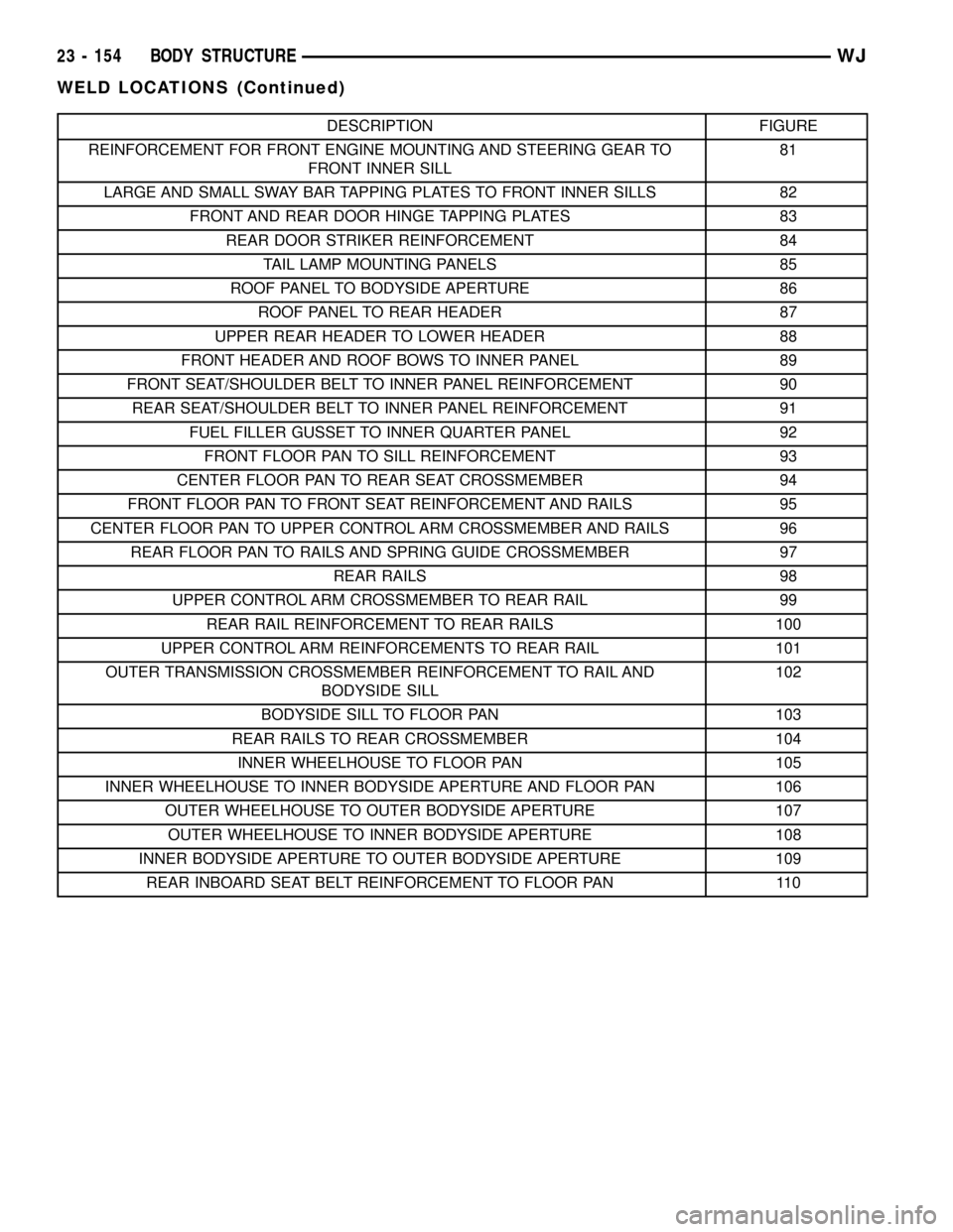
DESCRIPTION FIGURE
REINFORCEMENT FOR FRONT ENGINE MOUNTING AND STEERING GEAR TO
FRONT INNER SILL81
LARGE AND SMALL SWAY BAR TAPPING PLATES TO FRONT INNER SILLS 82
FRONT AND REAR DOOR HINGE TAPPING PLATES 83
REAR DOOR STRIKER REINFORCEMENT 84
TAIL LAMP MOUNTING PANELS 85
ROOF PANEL TO BODYSIDE APERTURE 86
ROOF PANEL TO REAR HEADER 87
UPPER REAR HEADER TO LOWER HEADER 88
FRONT HEADER AND ROOF BOWS TO INNER PANEL 89
FRONT SEAT/SHOULDER BELT TO INNER PANEL REINFORCEMENT 90
REAR SEAT/SHOULDER BELT TO INNER PANEL REINFORCEMENT 91
FUEL FILLER GUSSET TO INNER QUARTER PANEL 92
FRONT FLOOR PAN TO SILL REINFORCEMENT 93
CENTER FLOOR PAN TO REAR SEAT CROSSMEMBER 94
FRONT FLOOR PAN TO FRONT SEAT REINFORCEMENT AND RAILS 95
CENTER FLOOR PAN TO UPPER CONTROL ARM CROSSMEMBER AND RAILS 96
REAR FLOOR PAN TO RAILS AND SPRING GUIDE CROSSMEMBER 97
REAR RAILS 98
UPPER CONTROL ARM CROSSMEMBER TO REAR RAIL 99
REAR RAIL REINFORCEMENT TO REAR RAILS 100
UPPER CONTROL ARM REINFORCEMENTS TO REAR RAIL 101
OUTER TRANSMISSION CROSSMEMBER REINFORCEMENT TO RAIL AND
BODYSIDE SILL102
BODYSIDE SILL TO FLOOR PAN 103
REAR RAILS TO REAR CROSSMEMBER 104
INNER WHEELHOUSE TO FLOOR PAN 105
INNER WHEELHOUSE TO INNER BODYSIDE APERTURE AND FLOOR PAN 106
OUTER WHEELHOUSE TO OUTER BODYSIDE APERTURE 107
OUTER WHEELHOUSE TO INNER BODYSIDE APERTURE 108
INNER BODYSIDE APERTURE TO OUTER BODYSIDE APERTURE 109
REAR INBOARD SEAT BELT REINFORCEMENT TO FLOOR PAN 110
23 - 154 BODY STRUCTUREWJ
WELD LOCATIONS (Continued)
Page 2050 of 2199

Fig. 77 UPPER SILLS AND UPPER CONTROL ARM REINFORCEMENT AND BRACKETS TO FRONT SILLS
WJBODY STRUCTURE 23 - 177
WELD LOCATIONS (Continued)