2002 JEEP GRAND CHEROKEE engine chart
[x] Cancel search: engine chartPage 240 of 2199

(3) Install drive belt (Refer to 7 - COOLING/AC-
CESSORY DRIVE/DRIVE BELTS - INSTALLA-
TION).
(4) Check belt indexing marks (Refer to 7 - COOL-
ING/ACCESSORY DRIVE/DRIVE BELTS - INSTAL-
LATION).
INSTALLATIONÐ4.0L ENGINE
(1) Install tensioner assembly to mounting
bracket, align the two dowels on the tensioner with
the mounting bracket and hand start the bolt.
Tighten bolt to 28 N´m (250 in. lbs.).
CAUTION: To prevent damage to coil case, coil
mounting bolts must be torqued.
(2) Install drive belt. (Refer to 7 - COOLING/AC-
CESSORY DRIVE/DRIVE BELTS - INSTALLA-
TION).(3) Check belt indexing marks (Refer to 7 - COOL-
ING/ACCESSORY DRIVE/DRIVE BELTS - INSTAL-
LATION).
DRIVE BELTS - 4.0L
DIAGNOSIS AND TESTING ± SERPENTINE
DRIVE BELT
When diagnosing serpentine drive belts, small
cracks that run across ribbed surface of belt from rib
to rib (Fig. 3), are considered normal. These are not a
reason to replace belt. However, cracks running along
a rib (not across) arenotnormal. Any belt with
cracks running along a rib must be replaced (Fig. 3).
Also replace belt if it has excessive wear, frayed cords
or severe glazing.
Refer to SERPENTINE DRIVE BELT DIAGNOSIS
CHART for further belt diagnosis.
Fig. 2 Automatic Belt Tensioner
1 - IDLER PULLEY TIGHTEN TO 47 N´m (35 FT. LBS.)
2 - AUTOMATIC BELT TENSIONER
3 - GENERATOR MOUNTING BRACKET
Fig. 3 Serpentine Accessory Drive Belt Wear
Patterns
1 - NORMAL CRACKS BELT OK
2 - NOT NORMAL CRACKS REPLACE BELT
WJACCESSORY DRIVE 7 - 17
BELT TENSIONERS (Continued)
Page 243 of 2199

(2) Install new belt (Fig. 4). Route the belt around
all pulleys except the idler pulley. Rotate the ten-
sioner arm until it contacts its stop position. Route
the belt around the idler and slowly let the tensioner
rotate into the belt. Make sure the belt is seated onto
all pulleys.
(3) With the drive belt installed, inspect the belt
wear indicator (Fig. 5). On 4.0L Engines, the indica-
tor mark must be between the minimum and maxi-
mum marks. If the measurement exceedes this
specification replace the serpentine accessory drive
belt.DRIVE BELTS - 4.7L
DIAGNOSIS AND TESTING ± SERPENTINE
DRIVE BELT
When diagnosing serpentine drive belts, small
cracks that run across ribbed surface of belt from rib
to rib (Fig. 6), are considered normal. These are not a
reason to replace belt. However, cracks running along
a rib (not across) arenotnormal. Any belt with
cracks running along a rib must be replaced (Fig. 6).
Also replace belt if it has excessive wear, frayed cords
or severe glazing.
Refer to SERPENTINE DRIVE BELT DIAGNOSIS
CHART for further belt diagnosis.
Fig. 5 Accessory Drive Belt Wear Indicator
1 - INDICATOR MARK
2 - MINIMUM TENSION MARK
3 - MAXIMUM TENSION MARK
Fig. 6 Serpentine Accessory Drive Belt Wear
Patterns
1 - NORMAL CRACKS BELT OK
2 - NOT NORMAL CRACKS REPLACE BELT
7 - 20 ACCESSORY DRIVEWJ
DRIVE BELTS - 4.0L (Continued)
Page 330 of 2199

Certain mechanical failures within the input clutch
assembly can cause inadequate or out-of-range ele-
ment volumes. Also, defective Input/Output Speed
Sensors and wiring can cause these conditions. The
following chart identifies the appropriate clutch vol-
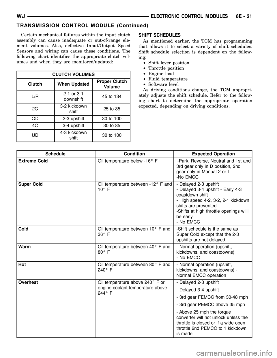
umes and when they are monitored/updated:
CLUTCH VOLUMES
Clutch When UpdatedProper Clutch
Volume
L/R2-1 or 3-1
downshift45 to 134
2C3-2 kickdown
shift25 to 85
OD 2-3 upshift 30 to 100
4C 3-4 upshift 30 to 85
UD4-3 kickdown
shift30 to 100
SHIFT SCHEDULES
As mentioned earlier, the TCM has programming
that allows it to select a variety of shift schedules.
Shift schedule selection is dependent on the follow-
ing:
²Shift lever position
²Throttle position
²Engine load
²Fluid temperature
²Software level
As driving conditions change, the TCM appropri-
ately adjusts the shift schedule. Refer to the follow-
ing chart to determine the appropriate operation
expected, depending on driving conditions.
Schedule Condition Expected Operation
Extreme ColdOil temperature below -16É F -Park, Reverse, Neutral and 1st and
3rd gear only in D position, 2nd
gear only in Manual 2 or L
-No EMCC
Super ColdOil temperature between -12É F and
10É F- Delayed 2-3 upshift
- Delayed 3-4 upshift - Early 4-3
coastdown shift
- High speed 4-2, 3-2, 2-1 kickdown
shifts are prevented
-Shifts at high throttle openings willl
be early.
- No EMCC
ColdOil temperature between 10É F and
36É F-Shift schedule is the same as
Super Cold except that the 2-3
upshifts are not delayed.
WarmOil temperature between 40É F and
80É F- Normal operation (upshift,
kickdowns, and coastdowns)
- No EMCC
HotOil temperature between 80É F and
240É F- Normal operation (upshift,
kickdowns, and coastdowns) -
Normal EMCC operation
OverheatOil temperature above 240É F or
engine coolant temperature above
244É F- Delayed 2-3 upshift
- Delayed 3-4 upshift
- 3rd gear FEMCC from 30-48 mph
- 3rd gear PEMCC above 35 mph
- Above 25 mph the torque
converter will not unlock unless the
throttle is closed or if a wide open
throttle 2nd PEMCC to 1 kickdown
is made
WJELECTRONIC CONTROL MODULES 8E - 21
TRANSMISSION CONTROL MODULE (Continued)
Page 660 of 2199

TERMINOLOGY
This is a list of terms and definitions used in the
wiring diagrams.
LHD .................Left Hand Drive Vehicles
RHD................Right Hand Drive Vehicles
ATX . . Automatic Transmissions-Front Wheel Drive
MTX....Manual Transmissions-Front Wheel Drive
AT ....Automatic Transmissions-Rear Wheel Drive
MT .....Manual Transmissions-Rear Wheel Drive
SOHC...........Single Over Head Cam Engine
DOHC..........Double Over Head Cam Engine
Built-Up-Export........ Vehicles Built For Sale In
Markets Other Than North America
Except Built-Up-Export . . Vehicles Built For Sale In
North America
DESCRIPTION - CIRCUIT INFORMATION
Each wire shown in the diagrams contains a code
which identifies the main circuit, part of the main
circuit, gage of wire, and color (Fig. 4).
WIRE COLOR CODE CHART
COLOR CODE COLOR
BL BLUE
BK BLACK
BR BROWN
DB DARK BLUE
DG DARK GREEN
GY GRAY
LB LIGHT BLUE
LG LIGHT GREEN
OR ORANGE
PK PINK
RD RED
TN TAN
VT VIOLET
WT WHITE
YL YELLOW
* WITH TRACER
Fig. 4 WIRE CODE IDENTIFICATION
1 - COLOR OF WIRE (LIGHT BLUE WITH YELLOW TRACER
2 - GAGE OF WIRE (18 GAGE)
3 - PART OF MAIN CIRCUIT (VARIES DEPENDING ON
EQUIPMENT)
4 - MAIN CIRCUIT IDENTIFICATION
WJ8W-01 WIRING DIAGRAM INFORMATION 8W - 01 - 5
WIRING DIAGRAM INFORMATION (Continued)
Page 662 of 2199

DESCRIPTION - CONNECTOR, GROUND AND
SPLICE INFORMATION
CAUTION: Not all connectors are serviced. Some
connectors are serviced only with a harness. A typ-
ical example might be the Supplemental Restraint
System connectors. Always check parts availability
before attempting a repair.
IDENTIFICATION
In-line connectors are identified by a number, as
follows:
²In-line connectors located in the engine compart-
ment are C100 series numbers
²In-line connectors located in the Instrument
Panel area are C200 series numbers.
²In-line connectors located in the body are C300
series numbers.
²Jumper harness connectors are C400 series
numbers.
²Grounds and ground connectors are identified
with a ªGº and follow the same series numbering as
the in-line connectors.
²Splices are identified with an ªSº and follow the
same series numbering as the in-line connectors.
²Component connectors are identified by the com-
ponent name instead of a number. Multiple connec-
tors on a component use a C1, C2, etc. identifier.
LOCATIONS
Section 8W-91 contains connector/ground/splice
location illustrations. The illustrations contain the
connector name (or number)/ground number/splice
number and component identification. Connector/
ground/splice location charts in section 8W-91 refer-
ence the figure numbers of the illustrations.
The abbreviation T/O is used in the component
location section to indicate a point in which the wir-
ing harness branches out to a component. The abbre-
viation N/S means Not Shown in the illustrations
WARNING
WARNINGS - GENERAL
WARNINGSprovide information to prevent per-
sonal injury and vehicle damage. Below is a list of
general warnings that should be followed any time a
vehicle is being serviced.
WARNING: ALWAYS WEAR SAFETY GLASSES FOR
EYE PROTECTION.
WARNING: USE SAFETY STANDS ANYTIME A PRO-
CEDURE REQUIRES BEING UNDER A VEHICLE.WARNING: BE SURE THAT THE IGNITION SWITCH
ALWAYS IS IN THE OFF POSITION, UNLESS THE
PROCEDURE REQUIRES IT TO BE ON.
WARNING: SET THE PARKING BRAKE WHEN
WORKING ON ANY VEHICLE. AN AUTOMATIC
TRANSMISSION SHOULD BE IN PARK. A MANUAL
TRANSMISSION SHOULD BE IN NEUTRAL.
WARNING: OPERATE THE ENGINE ONLY IN A
WELL-VENTILATED AREA.
WARNING: KEEP AWAY FROM MOVING PARTS
WHEN THE ENGINE IS RUNNING, ESPECIALLY THE
FAN AND BELTS.
WARNING: TO PREVENT SERIOUS BURNS, AVOID
CONTACT WITH HOT PARTS SUCH AS THE RADIA-
TOR, EXHAUST MANIFOLD(S), TAIL PIPE, CATA-
LYTIC CONVERTER AND MUFFLER.
WARNING: DO NOT ALLOW FLAME OR SPARKS
NEAR THE BATTERY. GASES ARE ALWAYS
PRESENT IN AND AROUND THE BATTERY.
WARNING: ALWAYS REMOVE RINGS, WATCHES,
LOOSE HANGING JEWELRY AND AVOID LOOSE
CLOTHING.
DIAGNOSIS AND TESTING - WIRING HARNESS
TROUBLESHOOTING TOOLS
When diagnosing a problem in an electrical circuit
there are several common tools necessary. These tools
are listed and explained below.
²Jumper Wire - This is a test wire used to con-
nect two points of a circuit. It can be used to bypass
an open in a circuit.
WARNING: NEVER USE A JUMPER WIRE ACROSS
A LOAD, SUCH AS A MOTOR, CONNECTED
BETWEEN A BATTERY FEED AND GROUND.
²Voltmeter - Used to check for voltage on a cir-
cuit. Always connect the black lead to a known good
ground and the red lead to the positive side of the
circuit.
CAUTION: Most of the electrical components used
in today's vehicles are Solid State. When checking
voltages in these circuits, use a meter with a 10 -
megohm or greater impedance rating.
WJ8W-01 WIRING DIAGRAM INFORMATION 8W - 01 - 7
WIRING DIAGRAM INFORMATION (Continued)
Page 1246 of 2199

²6th & 7th DigitsÐThe day of engine build (01 -
31).(1)FOR EXAMPLE:Code * 801MX12 * identifies
a 4.0 Liter (242 CID) engine with a multi-point fuel
injection system, 8.7:1 compression ratio and built on
January 12, 1998.
DIAGNOSIS AND TESTING
DIAGNOSIS AND TESTING - ENGINE
DIAGNOSIS - INTRODUCTION
Engine diagnosis is helpful in determining the
causes of malfunctions not detected and remedied by
routine maintenance.
These malfunctions may be classified as either
mechanical (e.g., a strange noise), or performance
(e.g., engine idles rough and stalls).
(Refer to 9 - ENGINE - DIAGNOSIS AND TEST-
ING - Preformance) or (Refer to 9 - ENGINE - DIAG-
NOSIS AND TESTING - Mechanical). Refer to 14 -
FUEL SYSTEM for fuel system diagnosis.
Additional tests and diagnostic procedures may be
necessary for specific engine malfunctions that can-
not be isolated with the Service Diagnosis charts.
Information concerning additional tests and diagno-
sis is provided within the following:
²Cylinder Compression Pressure Test (Refer to 9 -
ENGINE - DIAGNOSIS AND TESTING)
²Cylinder Combustion Pressure Leakage Test
(Refer to 9 - ENGINE - DIAGNOSIS AND TESTING)
²Cylinder Head Gasket Failure Diagnosis (Refer
to 9 - ENGINE/CYLINDER HEAD - DIAGNOSIS
AND TESTING)
²Intake Manifold Leakage Diagnosis (Refer to 9 -
ENGINE/MANIFOLDS/INTAKE MANIFOLD -
DIAGNOSIS AND TESTING)
²Lash Adjuster (Tappet) Noise Diagnosis (Refer to
9 - ENGINE/ENGINE BLOCK/HYDRAULIC LIFT-
ERS (CAM IN BLOCK) - DIAGNOSIS AND TEST-
ING)
²Engine Oil Leak Inspection (Refer to 9 -
ENGINE/LUBRICATION - DIAGNOSIS AND TEST-
ING)
Fig. 1 Engine Firing Order
Fig. 2 Build Date Code Location
1 - YEAR
2 - MONTH
3-DAY
WJENGINE - 4.0L 9 - 3
ENGINE - 4.0L (Continued)
Page 1247 of 2199

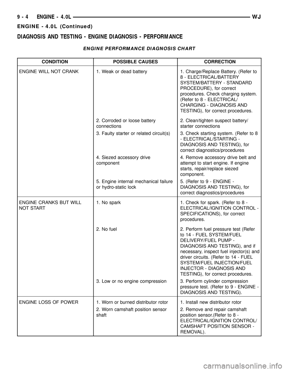
DIAGNOSIS AND TESTING - ENGINE DIAGNOSIS - PERFORMANCE
ENGINE PERFORMANCE DIAGNOSIS CHART
CONDITION POSSIBLE CAUSES CORRECTION
ENGINE WILL NOT CRANK 1. Weak or dead battery 1. Charge/Replace Battery. (Refer to
8 - ELECTRICAL/BATTERY
SYSTEM/BATTERY - STANDARD
PROCEDURE), for correct
procedures. Check charging system.
(Refer to 8 - ELECTRICAL/
CHARGING - DIAGNOSIS AND
TESTING), for correct procedures.
2. Corroded or loose battery
connections2. Clean/tighten suspect battery/
starter connections
3. Faulty starter or related circuit(s) 3. Check starting system. (Refer to 8
- ELECTRICAL/STARTING -
DIAGNOSIS AND TESTING), for
correct diagnostics/procedures
4. Siezed accessory drive
component4. Remove accessory drive belt and
attempt to start engine. If engine
starts, repair/replace siezed
component.
5. Engine internal mechanical failure
or hydro-static lock5. (Refer to 9 - ENGINE -
DIAGNOSIS AND TESTING), for
correct diagnostics/procedures
ENGINE CRANKS BUT WILL
NOT START1. No spark 1. Check for spark. (Refer to 8 -
ELECTRICAL/IGNITION CONTROL -
SPECIFICATIONS), for correct
procedures.
2. No fuel 2. Perform fuel pressure test (Refer
to 14 - FUEL SYSTEM/FUEL
DELIVERY/FUEL PUMP -
DIAGNOSIS AND TESTING), and if
necessary, inspect fuel injector(s) and
driver circuits. (Refer to 14 - FUEL
SYSTEM/FUEL INJECTION/FUEL
INJECTOR - DIAGNOSIS AND
TESTING), for correct procedures.
3. Low or no engine compression 3. Perform cylinder compression
pressure test. (Refer to 9 - ENGINE -
DIAGNOSIS AND TESTING).
ENGINE LOSS OF POWER 1. Worn or burned distributor rotor 1. Install new distributor rotor
2. Worn camshaft position sensor
shaft2. Remove and repair camshaft
position sensor.(Refer to 8 -
ELECTRICAL/IGNITION CONTROL/
CAMSHAFT POSITION SENSOR -
REMOVAL).
9 - 4 ENGINE - 4.0LWJ
ENGINE - 4.0L (Continued)
Page 1249 of 2199

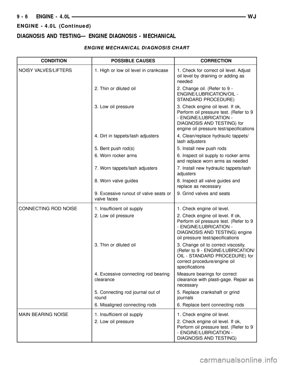
DIAGNOSIS AND TESTINGÐ ENGINE DIAGNOSIS - MECHANICAL
ENGINE MECHANICAL DIAGNOSIS CHART
CONDITION POSSIBLE CAUSES CORRECTION
NOISY VALVES/LIFTERS 1. High or low oil level in crankcase 1. Check for correct oil level. Adjust
oil level by draining or adding as
needed
2. Thin or diluted oil 2. Change oil. (Refer to 9 -
ENGINE/LUBRICATION/OIL -
STANDARD PROCEDURE)
3. Low oil pressure 3. Check engine oil level. If ok,
Perform oil pressure test. (Refer to 9
- ENGINE/LUBRICATION -
DIAGNOSIS AND TESTING) for
engine oil pressure test/specifications
4. Dirt in tappets/lash adjusters 4. Clean/replace hydraulic tappets/
lash adjusters
5. Bent push rod(s) 5. Install new push rods
6. Worn rocker arms 6. Inspect oil supply to rocker arms
and replace worn arms as needed
7. Worn tappets/lash adjusters 7. Install new hydraulic tappets/lash
adjusters
8. Worn valve guides 8. Inspect all valve guides and
replace as necessary
9. Excessive runout of valve seats or
valve faces9. Grind valves and seats
CONNECTING ROD NOISE 1. Insufficient oil supply 1. Check engine oil level.
2. Low oil pressure 2. Check engine oil level. If ok,
Perform oil pressure test. (Refer to 9
- ENGINE/LUBRICATION -
DIAGNOSIS AND TESTING) engine
oil pressure test/specifications
3. Thin or diluted oil 3. Change oil to correct viscosity.
(Refer to 9 - ENGINE/LUBRICATION/
OIL - STANDARD PROCEDURE) for
correct procedure/engine oil
specifications
4. Excessive connecting rod bearing
clearanceMeasure bearings for correct
clearance with plasti-gage. Repair as
necessary
5. Connecting rod journal out of
round5. Replace crankshaft or grind
journals
6. Misaligned connecting rods 6. Replace bent connecting rods
MAIN BEARING NOISE 1. Insufficient oil supply 1. Check engine oil level.
2. Low oil pressure 2. Check engine oil level. If ok,
Perform oil pressure test. (Refer to 9
- ENGINE/LUBRICATION -
DIAGNOSIS AND TESTING)
9 - 6 ENGINE - 4.0LWJ
ENGINE - 4.0L (Continued)