2002 JEEP GRAND CHEROKEE Trim
[x] Cancel search: TrimPage 1948 of 2199
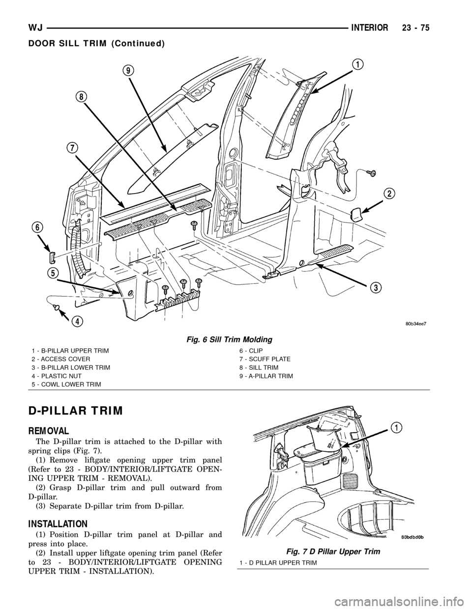
D-PILLAR TRIM
REMOVAL
The D-pillar trim is attached to the D-pillar with
spring clips (Fig. 7).
(1) Remove liftgate opening upper trim panel
(Refer to 23 - BODY/INTERIOR/LIFTGATE OPEN-
ING UPPER TRIM - REMOVAL).
(2) Grasp D-pillar trim and pull outward from
D-pillar.
(3) Separate D-pillar trim from D-pillar.
INSTALLATION
(1) Position D-pillar trim panel at D-pillar and
press into place.
(2) Install upper liftgate opening trim panel (Refer
to 23 - BODY/INTERIOR/LIFTGATE OPENING
UPPER TRIM - INSTALLATION).
Fig. 6 Sill Trim Molding
1 - B-PILLAR UPPER TRIM
2 - ACCESS COVER
3 - B-PILLAR LOWER TRIM
4 - PLASTIC NUT
5 - COWL LOWER TRIM6 - CLIP
7 - SCUFF PLATE
8 - SILL TRIM
9 - A-PILLAR TRIM
Fig. 7 D Pillar Upper Trim
1 - D PILLAR UPPER TRIM
WJINTERIOR 23 - 75
DOOR SILL TRIM (Continued)
Page 1950 of 2199
HEADLINER
REMOVAL
CAUTION: The headliner is a one-piece, molded
component. It has limited flexibility and must not be
bent. Damage may possibly result.
(1) Record radio presets and disconnect negative
battery cable.
(2) Remove A pillar trim moldings (Refer to 23 -
BODY/INTERIOR/A-PILLAR TRIM - REMOVAL).
(3) Remove B pillar upper trim moldings (Refer to
23 - BODY/INTERIOR/B-PILLAR UPPER TRIM -
REMOVAL).
(4) Remove C pillar trim moldings (Refer to 23 -
BODY/INTERIOR/C-PILLAR TRIM - REMOVAL).
(5) Remove D pillar trim molding (Refer to 23 -
BODY/INTERIOR/D-PILLAR TRIM - REMOVAL).
(6) Remove the sun visors (Refer to 23 - BODY/IN-
TERIOR/SUN VISOR - REMOVAL).
(7) Disconnect the vanity lamp electrical connector.
(8) Remove assist handles from roof rails (Refer to
23 - BODY/INTERIOR/ASSIST HANDLE - REMOV-
AL).
(9) Remove dome lamp and overhead console, if
equipped.
(10) Remove rear cargo/dome lamp.
(11) Remove sun roof pinch welt, if equipped.
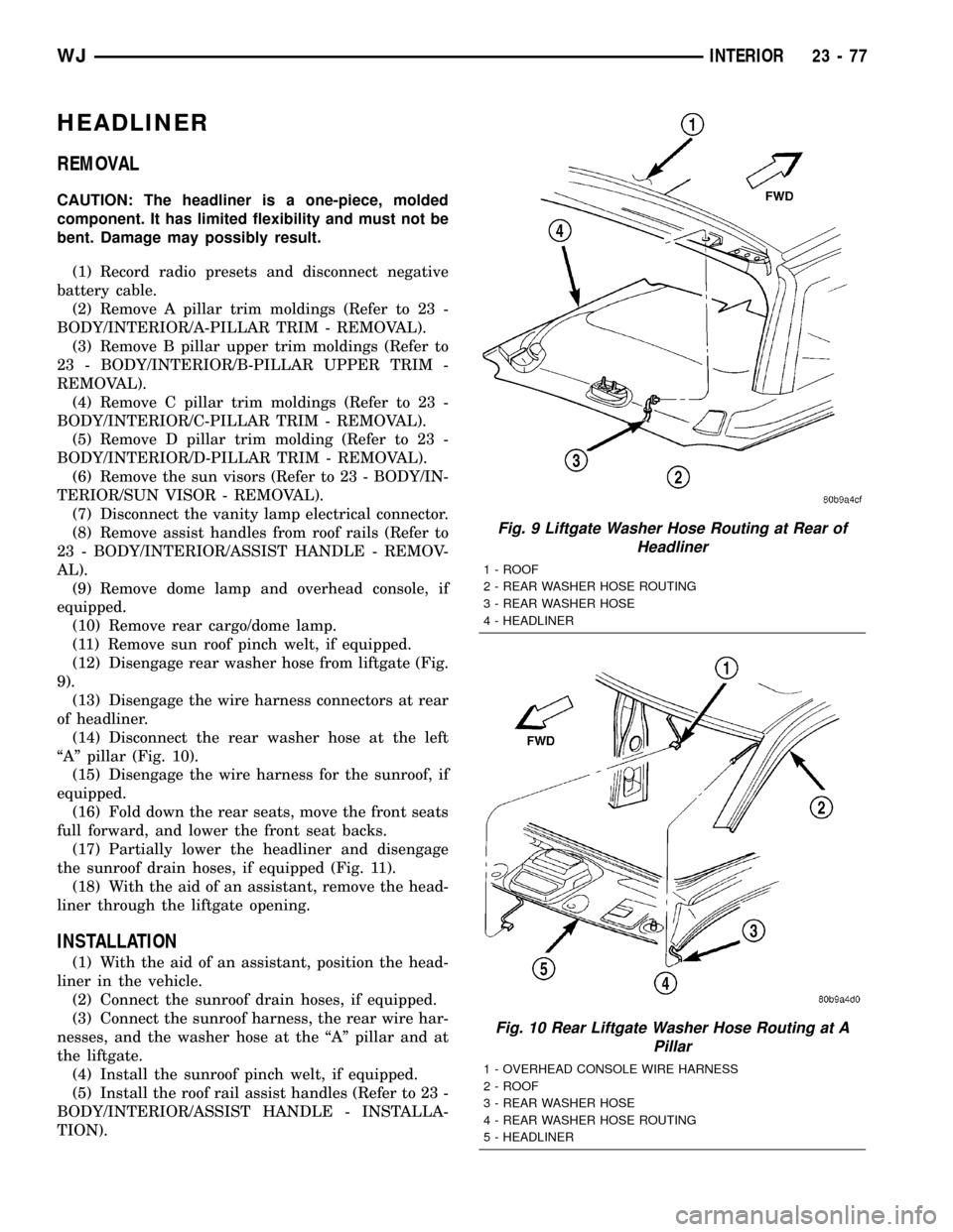
(12) Disengage rear washer hose from liftgate (Fig.
9).
(13) Disengage the wire harness connectors at rear
of headliner.
(14) Disconnect the rear washer hose at the left
ªAº pillar (Fig. 10).
(15) Disengage the wire harness for the sunroof, if
equipped.
(16) Fold down the rear seats, move the front seats
full forward, and lower the front seat backs.
(17) Partially lower the headliner and disengage
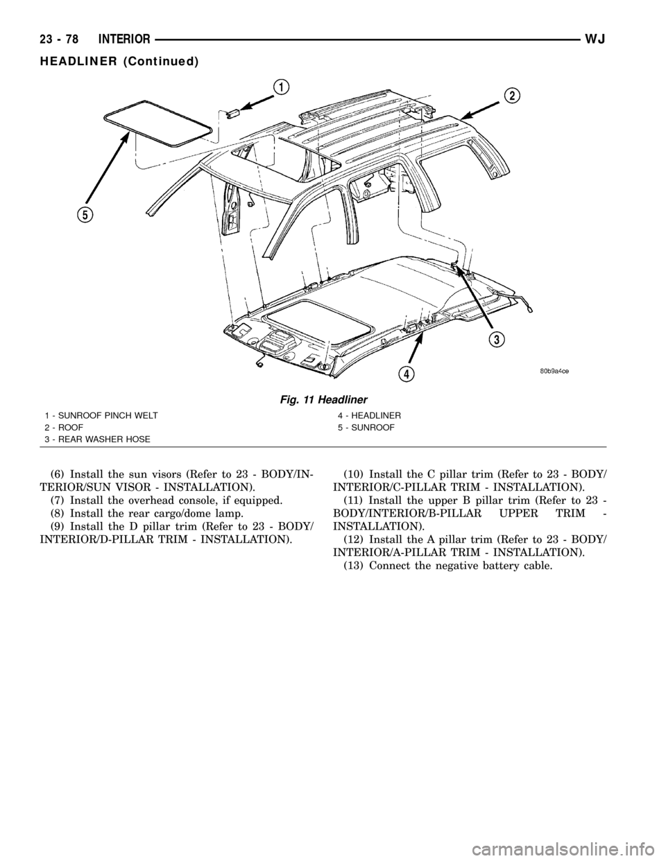
the sunroof drain hoses, if equipped (Fig. 11).
(18) With the aid of an assistant, remove the head-
liner through the liftgate opening.
INSTALLATION
(1) With the aid of an assistant, position the head-
liner in the vehicle.
(2) Connect the sunroof drain hoses, if equipped.
(3) Connect the sunroof harness, the rear wire har-
nesses, and the washer hose at the ªAº pillar and at
the liftgate.
(4) Install the sunroof pinch welt, if equipped.
(5) Install the roof rail assist handles (Refer to 23 -
BODY/INTERIOR/ASSIST HANDLE - INSTALLA-
TION).
Fig. 9 Liftgate Washer Hose Routing at Rear of
Headliner
1 - ROOF
2 - REAR WASHER HOSE ROUTING
3 - REAR WASHER HOSE
4 - HEADLINER
Fig. 10 Rear Liftgate Washer Hose Routing at A
Pillar
1 - OVERHEAD CONSOLE WIRE HARNESS
2 - ROOF
3 - REAR WASHER HOSE
4 - REAR WASHER HOSE ROUTING
5 - HEADLINER
WJINTERIOR 23 - 77
Page 1951 of 2199
(6) Install the sun visors (Refer to 23 - BODY/IN-
TERIOR/SUN VISOR - INSTALLATION).
(7) Install the overhead console, if equipped.
(8) Install the rear cargo/dome lamp.
(9) Install the D pillar trim (Refer to 23 - BODY/
INTERIOR/D-PILLAR TRIM - INSTALLATION).(10) Install the C pillar trim (Refer to 23 - BODY/
INTERIOR/C-PILLAR TRIM - INSTALLATION).
(11) Install the upper B pillar trim (Refer to 23 -
BODY/INTERIOR/B-PILLAR UPPER TRIM -
INSTALLATION).
(12) Install the A pillar trim (Refer to 23 - BODY/
INTERIOR/A-PILLAR TRIM - INSTALLATION).
(13) Connect the negative battery cable.
Fig. 11 Headliner
1 - SUNROOF PINCH WELT
2 - ROOF
3 - REAR WASHER HOSE4 - HEADLINER
5 - SUNROOF
23 - 78 INTERIORWJ
HEADLINER (Continued)
Page 1952 of 2199
LIFTGATE OPENING UPPER
TRIM
REMOVAL
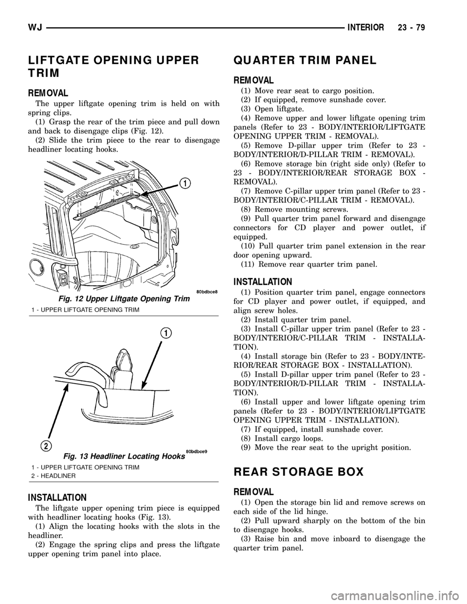
The upper liftgate opening trim is held on with
spring clips.
(1) Grasp the rear of the trim piece and pull down
and back to disengage clips (Fig. 12).
(2) Slide the trim piece to the rear to disengage
headliner locating hooks.
INSTALLATION
The liftgate upper opening trim piece is equipped
with headliner locating hooks (Fig. 13).
(1) Align the locating hooks with the slots in the
headliner.
(2) Engage the spring clips and press the liftgate
upper opening trim panel into place.
QUARTER TRIM PANEL
REMOVAL
(1) Move rear seat to cargo position.
(2) If equipped, remove sunshade cover.
(3) Open liftgate.
(4) Remove upper and lower liftgate opening trim
panels (Refer to 23 - BODY/INTERIOR/LIFTGATE
OPENING UPPER TRIM - REMOVAL).
(5) Remove D-pillar upper trim (Refer to 23 -
BODY/INTERIOR/D-PILLAR TRIM - REMOVAL).
(6) Remove storage bin (right side only) (Refer to
23 - BODY/INTERIOR/REAR STORAGE BOX -
REMOVAL).
(7) Remove C-pillar upper trim panel (Refer to 23 -
BODY/INTERIOR/C-PILLAR TRIM - REMOVAL).
(8) Remove mounting screws.
(9) Pull quarter trim panel forward and disengage
connectors for CD player and power outlet, if
equipped.
(10) Pull quarter trim panel extension in the rear
door opening upward.
(11) Remove rear quarter trim panel.
INSTALLATION
(1) Position quarter trim panel, engage connectors
for CD player and power outlet, if equipped, and
align screw holes.
(2) Install quarter trim panel.
(3) Install C-pillar upper trim panel (Refer to 23 -
BODY/INTERIOR/C-PILLAR TRIM - INSTALLA-
TION).
(4) Install storage bin (Refer to 23 - BODY/INTE-
RIOR/REAR STORAGE BOX - INSTALLATION).
(5) Install D-pillar upper trim panel (Refer to 23 -
BODY/INTERIOR/D-PILLAR TRIM - INSTALLA-
TION).
(6) Install upper and lower liftgate opening trim
panels (Refer to 23 - BODY/INTERIOR/LIFTGATE
OPENING UPPER TRIM - INSTALLATION).
(7) If equipped, install sunshade cover.
(8) Install cargo loops.
(9) Move the rear seat to the upright position.
REAR STORAGE BOX
REMOVAL
(1) Open the storage bin lid and remove screws on
each side of the lid hinge.
(2) Pull upward sharply on the bottom of the bin
to disengage hooks.
(3) Raise bin and move inboard to disengage the
quarter trim panel.
Fig. 12 Upper Liftgate Opening Trim
1 - UPPER LIFTGATE OPENING TRIM
Fig. 13 Headliner Locating Hooks
1 - UPPER LIFTGATE OPENING TRIM
2 - HEADLINER
WJINTERIOR 23 - 79
Page 1953 of 2199
INSTALLATION
(1) Position the bin hooks high in the slots on the
quarter trim panel.
(2) Push downward until the bin snaps into place.
(3) Install the hinge screws.
REAR VIEW MIRROR
REMOVAL
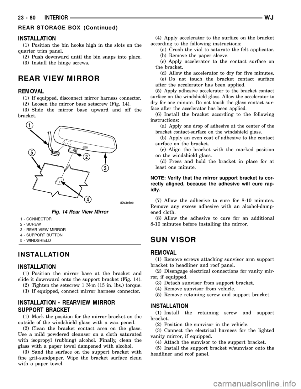
(1)If equipped, disconnect mirror harness connector.
(2) Loosen the mirror base setscrew (Fig. 14).
(3) Slide the mirror base upward and off the
bracket.
INSTALLATION
INSTALLATION
(1) Position the mirror base at the bracket and
slide it downward onto the support bracket (Fig. 14).
(2) Tighten the setscrew 1 N´m (15 in. lbs.) torque.
(3) If equipped, connect mirror harness connector.
INSTALLATION - REARVIEW MIRROR
SUPPORT BRACKET
(1) Mark the position for the mirror bracket on the
outside of the windshield glass with a wax pencil.
(2) Clean the bracket contact area on the glass.
Use a mild powdered cleanser on a cloth saturated
with isopropyl (rubbing) alcohol. Finally, clean the
glass with a paper towel dampened with alcohol.
(3) Sand the surface on the support bracket with
fine grit-sandpaper. Wipe the bracket surface clean
with a paper towel.(4) Apply accelerator to the surface on the bracket
according to the following instructions:
(a) Crush the vial to saturate the felt applicator.
(b) Remove the paper sleeve.
(c) Apply accelerator to the contact surface on
the bracket.
(d) Allow the accelerator to dry for five minutes.
(e) Do not touch the bracket contact surface
after the accelerator has been applied.
(5)
Apply adhesive accelerator to the bracket contact
surface on the windshield glass. Allow the accelerator to
dry for one minute. Do not touch the glass contact sur-
face after the accelerator has been applied.
(6) Install the bracket according to the following
instructions:
(a)
Apply one drop of adhesive at the center of the
bracket contact-surface on the windshield glass.
(b) Apply an even coat of adhesive to the contact
surface on the bracket.
(c) Align the bracket with the marked position
on the windshield glass.
(d) Press and hold the bracket in place for at
least one minute.
NOTE: Verify that the mirror support bracket is cor-
rectly aligned, because the adhesive will cure rap-
idly.
(7) Allow the adhesive to cure for 8-10 minutes.
Remove any excess adhesive with an alcohol-damp-
ened cloth.
(8) Allow the adhesive to cure for an additional
8-10 minutes before installing the mirror.
SUN VISOR
REMOVAL
(1) Remove screws attaching sunvisor arm support
bracket to headliner and roof panel.
(2) Disengage electrical connections for vanity mir-
ror, if equipped.
(3) Detach sunvisor from support bracket.
(4) Remove sunvisor from vehicle.
(5) Remove retaining screw and support bracket.
INSTALLATION
(1) Install the retaining screw and support
bracket.
(2) Position the sunvisor in the vehicle.
(3) Connect the electrical harness for the lighted
vanity mirror, if equipped.
(4) Attach the sunvisor to the support bracket.
(5) Install the support bracket w/sunvisor onto the
headliner and roof panel.
Fig. 14 Rear View Mirror
1 - CONNECTOR
2 - SCREW
3 - REAR VIEW MIRROR
4 - SUPPORT BUTTON
5 - WINDSHIELD
23 - 80 INTERIORWJ
REAR STORAGE BOX (Continued)
Page 1957 of 2199
FRONT HEADREST SLEEVE
REMOVAL
(1) Remove head restraint (Refer to 23 - BODY/
SEATS/FRONT HEADREST - REMOVAL).
(2) Remove seat back cover (Refer to 23 - BODY/
SEATS/FRONT SEAT BACK COVER - REMOVAL).
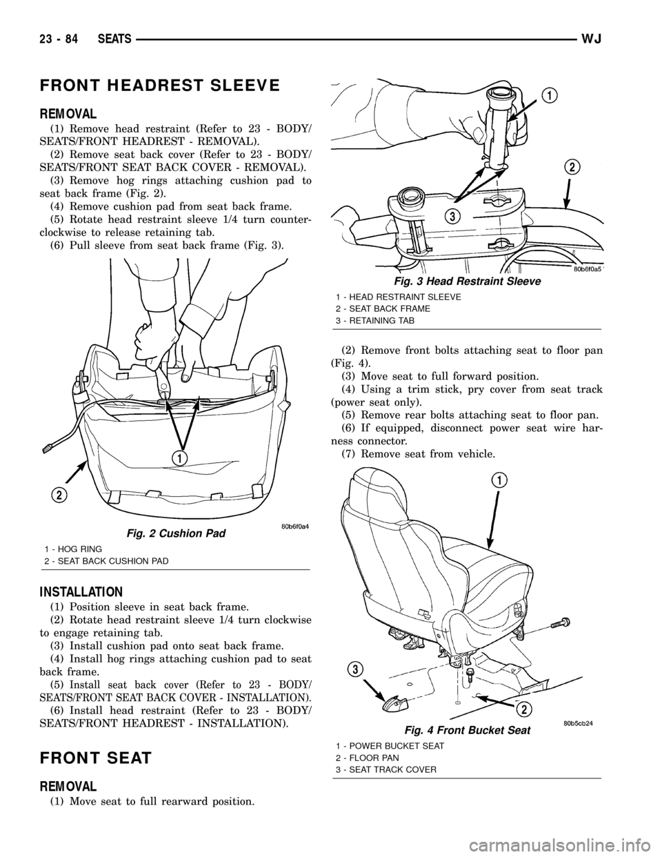
(3) Remove hog rings attaching cushion pad to
seat back frame (Fig. 2).
(4) Remove cushion pad from seat back frame.
(5) Rotate head restraint sleeve 1/4 turn counter-
clockwise to release retaining tab.
(6) Pull sleeve from seat back frame (Fig. 3).
INSTALLATION
(1) Position sleeve in seat back frame.
(2) Rotate head restraint sleeve 1/4 turn clockwise
to engage retaining tab.
(3) Install cushion pad onto seat back frame.
(4) Install hog rings attaching cushion pad to seat
back frame.
(5)
Install seat back cover (Refer to 23 - BODY/
SEATS/FRONT SEAT BACK COVER - INSTALLATION).
(6) Install head restraint (Refer to 23 - BODY/
SEATS/FRONT HEADREST - INSTALLATION).
FRONT SEAT
REMOVAL
(1) Move seat to full rearward position.(2) Remove front bolts attaching seat to floor pan
(Fig. 4).
(3) Move seat to full forward position.
(4) Using a trim stick, pry cover from seat track
(power seat only).
(5) Remove rear bolts attaching seat to floor pan.
(6) If equipped, disconnect power seat wire har-
ness connector.
(7) Remove seat from vehicle.
Fig. 2 Cushion Pad
1 - HOG RING
2 - SEAT BACK CUSHION PAD
Fig. 3 Head Restraint Sleeve
1 - HEAD RESTRAINT SLEEVE
2 - SEAT BACK FRAME
3 - RETAINING TAB
Fig. 4 Front Bucket Seat
1 - POWER BUCKET SEAT
2 - FLOOR PAN
3 - SEAT TRACK COVER
23 - 84 SEATSWJ
Page 1958 of 2199
INSTALLATION
(1) Position seat on floor pan.
(2) If equipped, connect power seat wire harness
connector.
(3) Install rear bolts attaching seat to floor pan.
Tighten bolts to 40 N´m (30 ft. lbs.) torque.
(4) If equipped, install cover on seat track.
(5) Move seat to full rearward position.
(6) Install front bolts attaching seat to floor pan.
Tighten bolts to 40 N´m (30 ft. lbs.) torque.
FRONT SEAT BACK
REMOVAL
(1) Move seat to full rearward position.
(2) Remove inboard bolt attaching seat back frame
to seat cushion frame.
(3) Move seat to full forward position.
(4) Move seat back to full recline position.
(5) Remove screws attaching seat side shield to
seat frame.
(6) Disconnect wire harness connector from
recliner motor, if equipped.
(7) From the underside of the seat, disconnect the
wire harness connector for the power lumber and/or
heated seat, if equipped.
(8) Remove outboard bolts attaching recliner to
seat cushion frame.
(9) Route the power lumber and/or heated seat
harness through the seat cushion cover, if equipped.
(10) Separate seat back from seat cushion.
INSTALLATION
(1) Position seat back on seat cushion.
(2) Route the power lumber and heater harness
through the seat cushion cover, if equipped.
(3) Install recliner bolts attaching seat back frame
to seat cushion frame. Tighten bolts to 28 N´m (20 ft.
lbs.) torque.
(4) Install the inboard bolt attaching seat back
frame to seat cushion frame. Tighten bolt to 47N´m
(35 ft.lbs.).
(5) Connect wire harness connector to recliner
motor and/or heated seat, if equipped.
(6) From the underside of the seat, connect the
power lumber and/or heated seat wire harness con-
nector to the seat harness, if equipped.
(7) Install screws attaching seat side shield to seat
frame.
FRONT SEAT BACK COVER
REMOVAL
(1) Remove head restraint (Refer to 23 - BODY/
SEATS/FRONT HEADREST - REMOVAL).
(2) Using a trim stick, carefully pry head restraint
release button caps from the top of seat back.
(3) Remove seat back (Refer to 23 - BODY/SEATS/
FRONT SEAT BACK - REMOVAL).
(4) Disengage J-strap at base of seat back.
(5) Slide hand between the face of the seat back
pad and the cushion cover and carefully separate
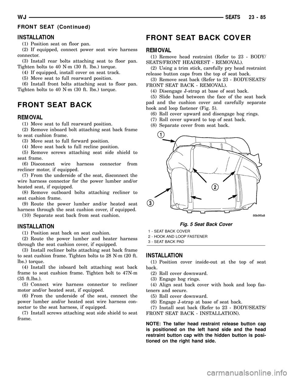
hook and loop fastener (Fig. 5).
(6) Roll cover upward and disengage hog rings.
(7) Roll cover upward to top of seat back.
(8) Separate cover from seat back.
INSTALLATION
(1) Position cover inside-out at the top of seat
back.
(2) Roll cover downward.
(3) Engage hog rings.
(4) Align seat back cover with hook and loop fas-
teners and secure.
(5) Roll cover downward.
(6) Engage J-strap at base of seat back.
(7) Install seat back (Refer to 23 - BODY/SEATS/
FRONT SEAT BACK - INSTALLATION).
NOTE: The taller head restraint release button cap
is positioned on the left hand side and the head
restraint button cap with the hidden button is posi-
tioned on the right hand side.
Fig. 5 Seat Back Cover
1 - SEAT BACK COVER
2 - HOOK AND LOOP FASTENER
3 - SEAT BACK PAD
WJSEATS 23 - 85
FRONT SEAT (Continued)
Page 1960 of 2199
SEAT TRACK ADJUSTER
REMOVAL
(1) Remove seat (Refer to 23 - BODY/SEATS/
FRONT SEAT - REMOVAL).
(2) Remove side shield (Refer to 23 - BODY/
SEATS/FRONT SEAT SIDE SHIELD - REMOVAL).
(3) Remove nuts attaching seat track adjuster to
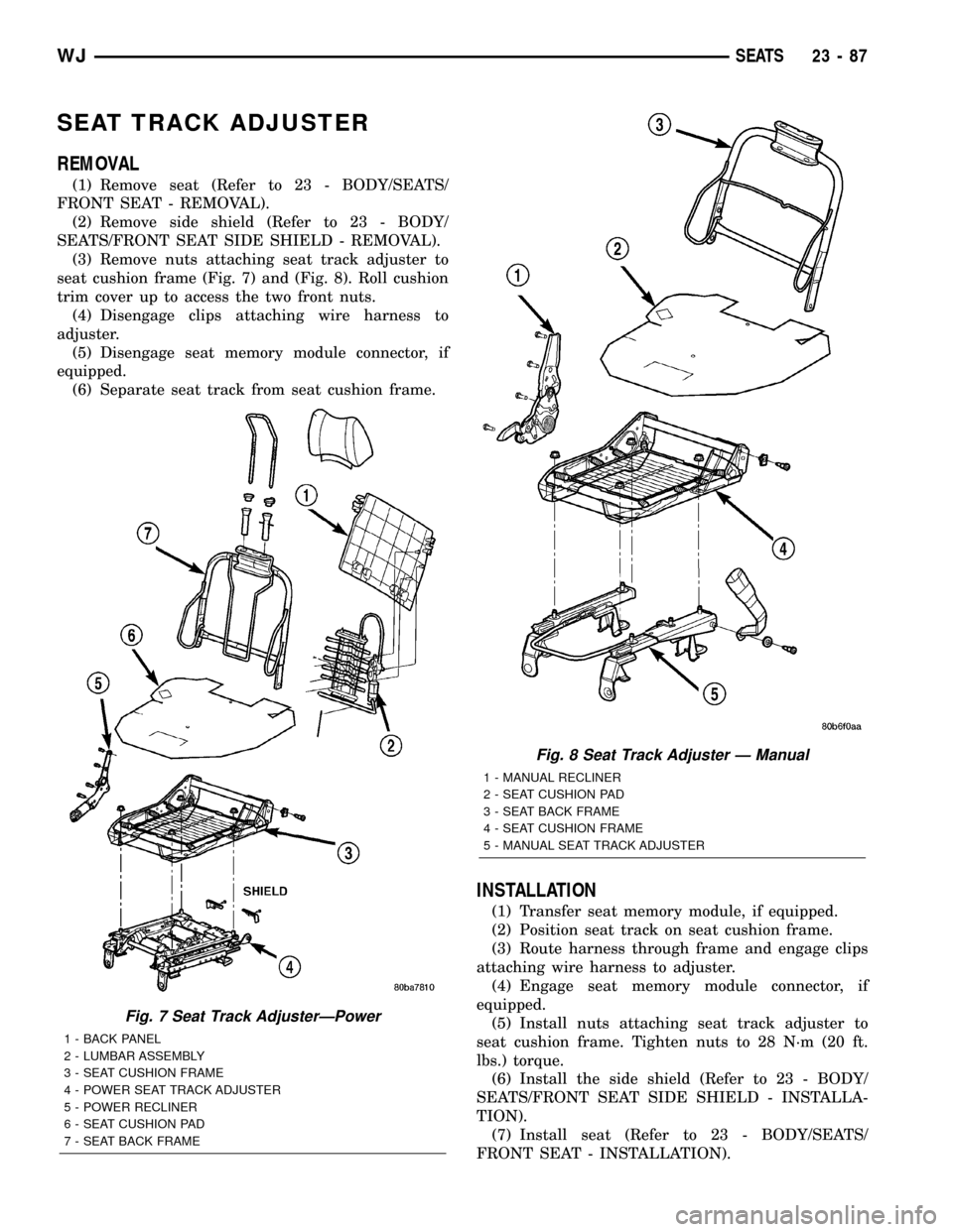
seat cushion frame (Fig. 7) and (Fig. 8). Roll cushion
trim cover up to access the two front nuts.
(4) Disengage clips attaching wire harness to
adjuster.
(5) Disengage seat memory module connector, if
equipped.
(6) Separate seat track from seat cushion frame.
INSTALLATION
(1) Transfer seat memory module, if equipped.
(2) Position seat track on seat cushion frame.
(3) Route harness through frame and engage clips
attaching wire harness to adjuster.
(4) Engage seat memory module connector, if
equipped.
(5) Install nuts attaching seat track adjuster to
seat cushion frame. Tighten nuts to 28 N´m (20 ft.
lbs.) torque.
(6) Install the side shield (Refer to 23 - BODY/
SEATS/FRONT SEAT SIDE SHIELD - INSTALLA-
TION).
(7) Install seat (Refer to 23 - BODY/SEATS/
FRONT SEAT - INSTALLATION).
Fig. 7 Seat Track AdjusterÐPower
1 - BACK PANEL
2 - LUMBAR ASSEMBLY
3 - SEAT CUSHION FRAME
4 - POWER SEAT TRACK ADJUSTER
5 - POWER RECLINER
6 - SEAT CUSHION PAD
7 - SEAT BACK FRAME
Fig. 8 Seat Track Adjuster Ð Manual
1 - MANUAL RECLINER
2 - SEAT CUSHION PAD
3 - SEAT BACK FRAME
4 - SEAT CUSHION FRAME
5 - MANUAL SEAT TRACK ADJUSTER
WJSEATS 23 - 87