2002 JEEP GRAND CHEROKEE set 1 2
[x] Cancel search: set 1 2Page 1232 of 2199
(5) Reconnect the right and left body wire harness
bulkhead connectors to the connector receptacles
located near the center of the JB.
(6) Install and tighten the screws that secure the
right and left body wire harness bulkhead connectors
to the connector receptacles located near the center
of the JB. Tighten the screws to 2.2 N´m (20 in. lbs.).
(7) Reconnect the fused B(+) and the IOD wire
harness connectors to the connector receptacles
located near the bottom of the JB.
(8) Reach behind the JB to reconnect the instru-
ment panel wire harness bulkhead connector to the
connector receptacle located near the top of the JB.
(9) Install and tighten the screw that secures the
instrument panel wire harness bulkhead connector to
the connector receptacle located near the top of the
JB. Tighten the screw to 2.2 N´m (20 in. lbs.).
(10)
Reach behind the JB to reconnect the two
instrument panel wire harness connectors to the BCM
connector receptacles located near the bottom of the JB.
(11) Install the steering column opening cover onto
the instrument panel. Refer toSteering Column
Opening Coverin Body for the location of the steer-
ing column opening cover installation procedures.
(12)
Install the fuse cover onto the bottom of the JB.
(13) Reconnect the battery negative cable.
POWER DISTRIBUTION
CENTER
DESCRIPTION
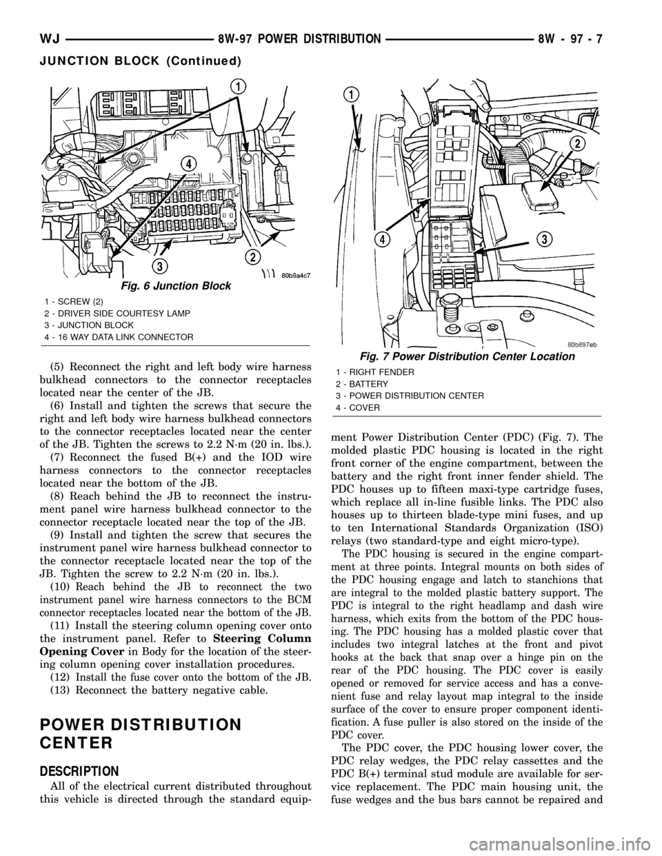
All of the electrical current distributed throughout
this vehicle is directed through the standard equip-ment Power Distribution Center (PDC) (Fig. 7). The
molded plastic PDC housing is located in the right
front corner of the engine compartment, between the
battery and the right front inner fender shield. The
PDC houses up to fifteen maxi-type cartridge fuses,
which replace all in-line fusible links. The PDC also
houses up to thirteen blade-type mini fuses, and up
to ten International Standards Organization (ISO)
relays (two standard-type and eight micro-type).
The PDC housing is secured in the engine compart-
ment at three points. Integral mounts on both sides of
the PDC housing engage and latch to stanchions that
are integral to the molded plastic battery support. The
PDC is integral to the right headlamp and dash wire
harness, which exits from the bottom of the PDC hous-
ing. The PDC housing has a molded plastic cover that
includes two integral latches at the front and pivot
hooks at the back that snap over a hinge pin on the
rear of the PDC housing. The PDC cover is easily
opened or removed for service access and has a conve-
nient fuse and relay layout map integral to the inside
surface of the cover to ensure proper component identi-
fication. A fuse puller is also stored on the inside of the
PDC cover.
The PDC cover, the PDC housing lower cover, the
PDC relay wedges, the PDC relay cassettes and the
PDC B(+) terminal stud module are available for ser-
vice replacement. The PDC main housing unit, the
fuse wedges and the bus bars cannot be repaired and
Fig. 6 Junction Block
1 - SCREW (2)
2 - DRIVER SIDE COURTESY LAMP
3 - JUNCTION BLOCK
4 - 16 WAY DATA LINK CONNECTOR
Fig. 7 Power Distribution Center Location
1 - RIGHT FENDER
2 - BATTERY
3 - POWER DISTRIBUTION CENTER
4 - COVER
WJ8W-97 POWER DISTRIBUTION 8W - 97 - 7
JUNCTION BLOCK (Continued)
Page 1234 of 2199
(9) Remove the PDC and the right headlamp and
dash wire harness from the engine compartment as a
unit.
DISASSEMBLY
POWER DISTRIBUTION CENTER DISASSEMBLY
PDC HOUSING LOWER COVER REMOVAL
The Power Distribution Center (PDC) cover, the
PDC housing lower cover, the PDC relay wedges, the
PDC relay cassettes and the PDC B(+) terminal stud
module are available for service replacement. The
PDC cover can be simply unlatched and removed
from the PDC housing without the PDC being
removed or disassembled. Service of the remaining
PDC components requires that the PDC be removed
from its mounting and disassembled. Refer toWiring
Repairin Wiring Diagrams for the location of the
wiring repair procedures.
(1) Remove the battery from the battery support.
Refer toBattery Systemfor the location of the bat-
tery removal procedures.
(2) Unlatch and remove the cover from the PDC.
(3) Remove the two nuts that secure the two-holed
eyelet of the battery wire harness PDC take out to
the B(+) terminal studs near the front of the PDC.
(4) Remove the battery wire harness PDC take out
eyelet from the two PDC B(+) terminal studs.
(5) Disengage the latches on the PDC housing
mounts from the tabs on the PDC mounting stan-
chions on the battery support, and pull the PDC
housing upward to disengage the mounts from the
stanchions.
(6) Where the right headlamp and dash wire har-
ness exits the PDC, remove the tape that secures the
wire harness to the trough formation on the PDC
housing lower cover.
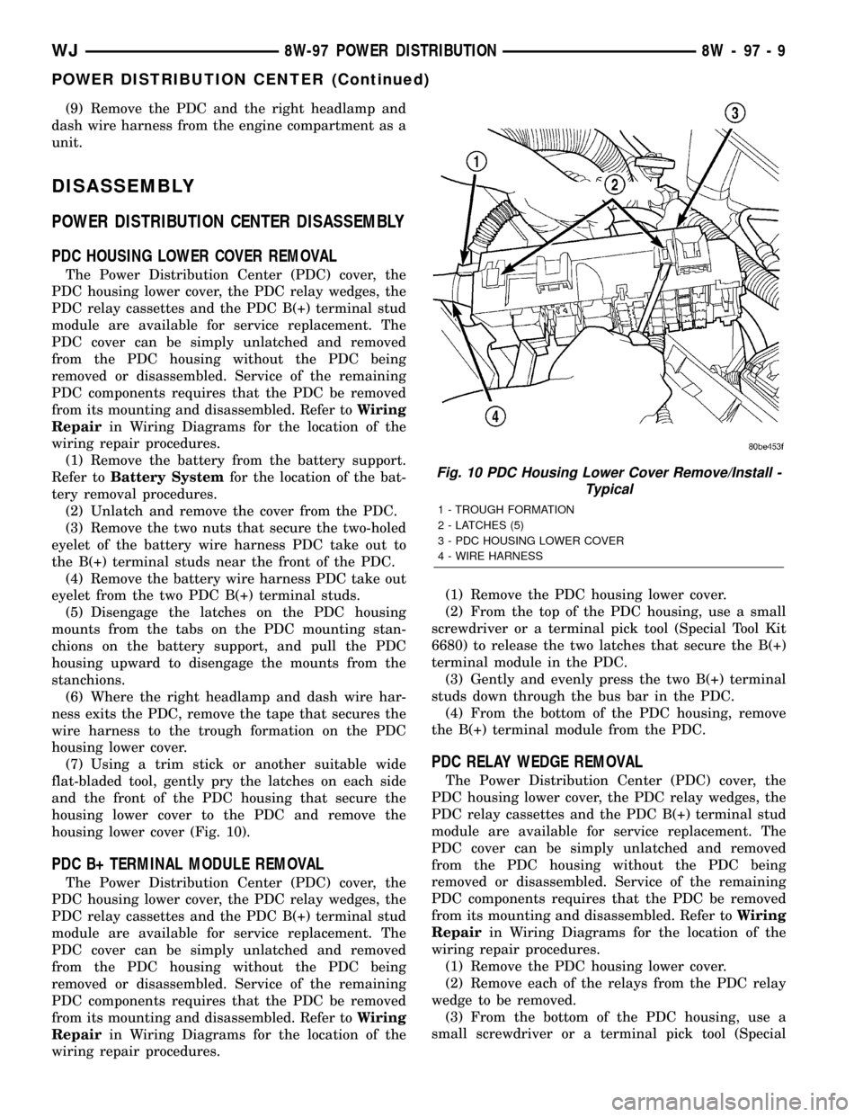
(7) Using a trim stick or another suitable wide
flat-bladed tool, gently pry the latches on each side
and the front of the PDC housing that secure the
housing lower cover to the PDC and remove the
housing lower cover (Fig. 10).
PDC B+ TERMINAL MODULE REMOVAL
The Power Distribution Center (PDC) cover, the
PDC housing lower cover, the PDC relay wedges, the
PDC relay cassettes and the PDC B(+) terminal stud
module are available for service replacement. The
PDC cover can be simply unlatched and removed
from the PDC housing without the PDC being
removed or disassembled. Service of the remaining
PDC components requires that the PDC be removed
from its mounting and disassembled. Refer toWiring
Repairin Wiring Diagrams for the location of the
wiring repair procedures.(1) Remove the PDC housing lower cover.
(2) From the top of the PDC housing, use a small
screwdriver or a terminal pick tool (Special Tool Kit
6680) to release the two latches that secure the B(+)
terminal module in the PDC.
(3) Gently and evenly press the two B(+) terminal
studs down through the bus bar in the PDC.
(4) From the bottom of the PDC housing, remove
the B(+) terminal module from the PDC.
PDC RELAY WEDGE REMOVAL
The Power Distribution Center (PDC) cover, the
PDC housing lower cover, the PDC relay wedges, the
PDC relay cassettes and the PDC B(+) terminal stud
module are available for service replacement. The
PDC cover can be simply unlatched and removed
from the PDC housing without the PDC being
removed or disassembled. Service of the remaining
PDC components requires that the PDC be removed
from its mounting and disassembled. Refer toWiring
Repairin Wiring Diagrams for the location of the
wiring repair procedures.
(1) Remove the PDC housing lower cover.
(2) Remove each of the relays from the PDC relay
wedge to be removed.
(3) From the bottom of the PDC housing, use a
small screwdriver or a terminal pick tool (Special
Fig. 10 PDC Housing Lower Cover Remove/Install -
Typical
1 - TROUGH FORMATION
2 - LATCHES (5)
3 - PDC HOUSING LOWER COVER
4 - WIRE HARNESS
WJ8W-97 POWER DISTRIBUTION 8W - 97 - 9
POWER DISTRIBUTION CENTER (Continued)
Page 1235 of 2199
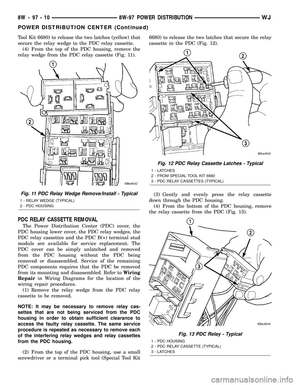
Tool Kit 6680) to release the two latches (yellow) that
secure the relay wedge to the PDC relay cassette.
(4) From the top of the PDC housing, remove the
relay wedge from the PDC relay cassette (Fig. 11).
PDC RELAY CASSETTE REMOVAL
The Power Distribution Center (PDC) cover, the
PDC housing lower cover, the PDC relay wedges, the
PDC relay cassettes and the PDC B(+) terminal stud
module are available for service replacement. The
PDC cover can be simply unlatched and removed
from the PDC housing without the PDC being
removed or disassembled. Service of the remaining
PDC components requires that the PDC be removed
from its mounting and disassembled. Refer toWiring
Repairin Wiring Diagrams for the location of the
wiring repair procedures.
(1) Remove the relay wedge from the PDC relay
cassette to be removed.
NOTE: It may be necessary to remove relay cas-
settes that are not being serviced from the PDC
housing in order to obtain sufficient clearance to
access the faulty relay cassette. The same service
procedure is repeated as necessary to remove each
of the interfering relay wedges and relay cassettes
from the PDC housing.
(2) From the top of the PDC housing, use a small
screwdriver or a terminal pick tool (Special Tool Kit6680) to release the two latches that secure the relay
cassette in the PDC (Fig. 12).
(3) Gently and evenly press the relay cassette
down through the PDC housing.
(4) From the bottom of the PDC housing, remove
the relay cassette from the PDC (Fig. 13).
Fig. 11 PDC Relay Wedge Remove/Install - Typical
1 - RELAY WEDGE (TYPICAL)
2 - PDC HOUSING
Fig. 12 PDC Relay Cassette Latches - Typical
1 - LATCHES
2 - FROM SPECIAL TOOL KIT 6680
3 - PDC RELAY CASSETTES (TYPICAL)
Fig. 13 PDC Relay - Typical
1 - PDC HOUSING
2 - PDC RELAY CASSETTE (TYPICAL)
3 - LATCHES
8W - 97 - 10 8W-97 POWER DISTRIBUTIONWJ
POWER DISTRIBUTION CENTER (Continued)
Page 1236 of 2199
CAUTION: Do not remove the wiring and terminals
from the terminal cavities of the faulty PDC relay
cassette at this time. Refer to the Assembly proce-
dure that follows for the proper procedures for
transferring the wiring and terminals to the replace-
ment PDC relay cassette.
ASSEMBLY
POWER DISTRIBUTION CENTER ASSEMBLY
PDC B(+) TERMINAL MODULE INSTALLATION
(1) From the bottom of the PDC housing, align and
insert the B(+) terminal module into the PDC.
(2) From the bottom of the PDC housing, align and
insert the two studs of the PDC B(+) terminal mod-
ule through the bus bar in the PDC.
(3) From the bottom of the PDC housing, press the
B(+) terminal module gently and evenly into the PDC
until both of the latches are fully engaged.
(4) Install the PDC housing lower cover.
RELAY WEDGE INSTALLATION
(1) From the top of the PDC housing, align and
insert the PDC relay wedge latch arms into the cor-
rect cavities in the relay cassette.
(2) Gently and evenly press the PDC relay wedge
down into the relay cassette until both of the latches
are fully engaged.
(3) Install each of the removed relays into the
proper cavities of the PDC relay wedge.
(4) Install the PDC housing lower cover.
RELAY CASSETTE INSTALLATION
(1) Move the faulty PDC relay cassette with its
wiring away from the bottom of the PDC housing far
enough to allow the replacement relay cassette to be
installed into the PDC.
(2) Using the faulty relay cassette as a guide, be
certain that the replacement relay cassette is cor-
rectly oriented before installing it into the PDC hous-
ing.
(3) From the bottom of the PDC housing, align and
insert the replacement relay cassette into the PDC.
Press the relay cassette up into the PDC until both
of the latches are fully engaged.
CAUTION: Proper care must be taken to be certain
that the wiring and terminals from the faulty PDC
relay cassette are installed in the correct terminal
cavities of the replacement relay cassette. To pre-
vent mistakes it is recommended that the wiring
and terminals be removed from the faulty relay cas-
sette one cavity at a time, repaired or spliced as
necessary, then installed securely into the correctcavity of the replacement relay cassette. If you are
not absolutely certain into which cavity a terminal
should be installed, refer to Power Distribution in
the index of this service manual for the location of
complete circuit diagrams covering the PDC.
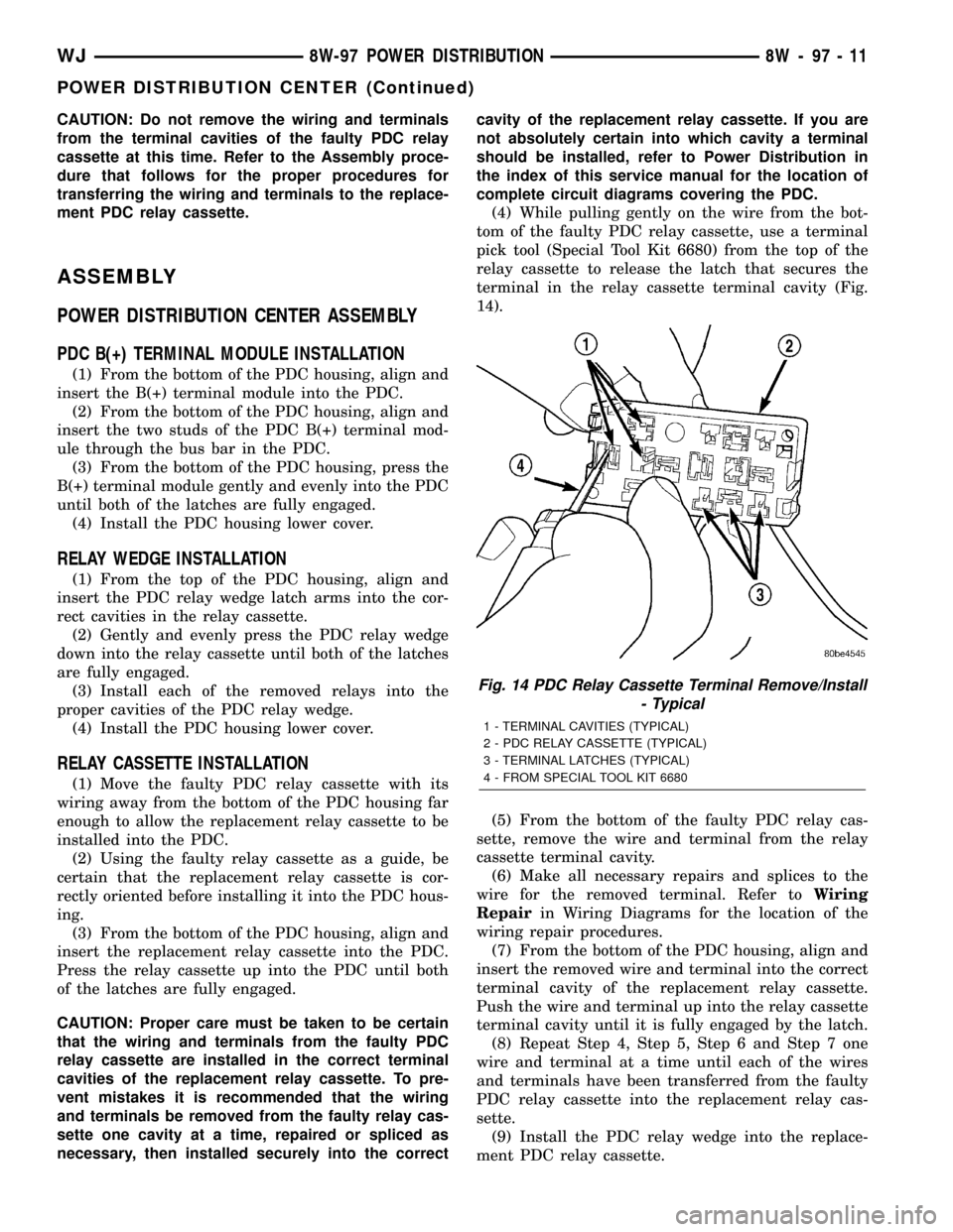
(4) While pulling gently on the wire from the bot-
tom of the faulty PDC relay cassette, use a terminal
pick tool (Special Tool Kit 6680) from the top of the
relay cassette to release the latch that secures the
terminal in the relay cassette terminal cavity (Fig.
14).
(5) From the bottom of the faulty PDC relay cas-
sette, remove the wire and terminal from the relay
cassette terminal cavity.
(6) Make all necessary repairs and splices to the
wire for the removed terminal. Refer toWiring
Repairin Wiring Diagrams for the location of the
wiring repair procedures.
(7) From the bottom of the PDC housing, align and
insert the removed wire and terminal into the correct
terminal cavity of the replacement relay cassette.
Push the wire and terminal up into the relay cassette
terminal cavity until it is fully engaged by the latch.
(8) Repeat Step 4, Step 5, Step 6 and Step 7 one
wire and terminal at a time until each of the wires
and terminals have been transferred from the faulty
PDC relay cassette into the replacement relay cas-
sette.
(9) Install the PDC relay wedge into the replace-
ment PDC relay cassette.
Fig. 14 PDC Relay Cassette Terminal Remove/Install
- Typical
1 - TERMINAL CAVITIES (TYPICAL)
2 - PDC RELAY CASSETTE (TYPICAL)
3 - TERMINAL LATCHES (TYPICAL)
4 - FROM SPECIAL TOOL KIT 6680
WJ8W-97 POWER DISTRIBUTION 8W - 97 - 11
POWER DISTRIBUTION CENTER (Continued)
Page 1248 of 2199
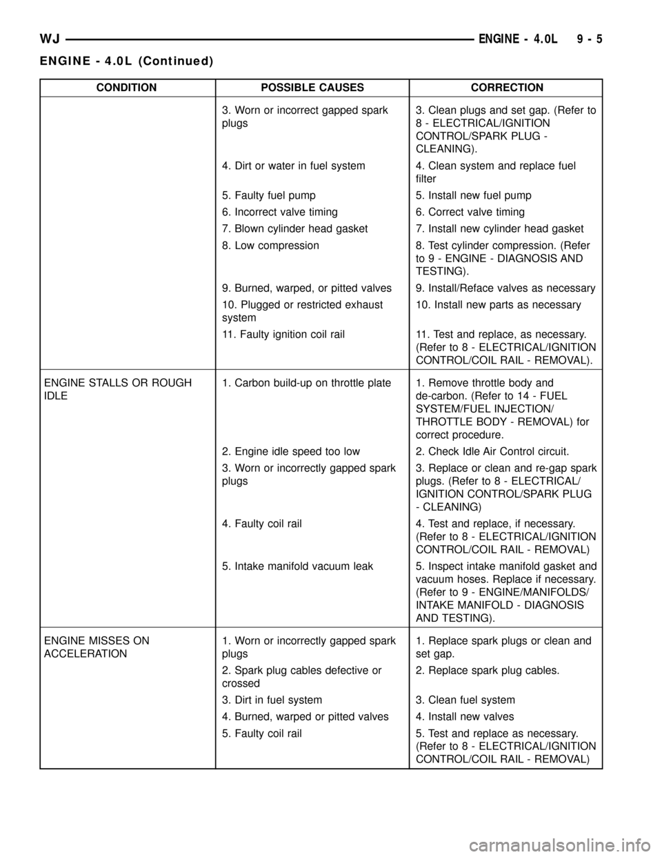
CONDITION POSSIBLE CAUSES CORRECTION
3. Worn or incorrect gapped spark
plugs3. Clean plugs and set gap. (Refer to
8 - ELECTRICAL/IGNITION
CONTROL/SPARK PLUG -
CLEANING).
4. Dirt or water in fuel system 4. Clean system and replace fuel
filter
5. Faulty fuel pump 5. Install new fuel pump
6. Incorrect valve timing 6. Correct valve timing
7. Blown cylinder head gasket 7. Install new cylinder head gasket
8. Low compression 8. Test cylinder compression. (Refer
to 9 - ENGINE - DIAGNOSIS AND
TESTING).
9. Burned, warped, or pitted valves 9. Install/Reface valves as necessary
10. Plugged or restricted exhaust
system10. Install new parts as necessary
11. Faulty ignition coil rail 11. Test and replace, as necessary.
(Refer to 8 - ELECTRICAL/IGNITION
CONTROL/COIL RAIL - REMOVAL).
ENGINE STALLS OR ROUGH
IDLE1. Carbon build-up on throttle plate 1. Remove throttle body and
de-carbon. (Refer to 14 - FUEL
SYSTEM/FUEL INJECTION/
THROTTLE BODY - REMOVAL) for
correct procedure.
2. Engine idle speed too low 2. Check Idle Air Control circuit.
3. Worn or incorrectly gapped spark
plugs3. Replace or clean and re-gap spark
plugs. (Refer to 8 - ELECTRICAL/
IGNITION CONTROL/SPARK PLUG
- CLEANING)
4. Faulty coil rail 4. Test and replace, if necessary.
(Refer to 8 - ELECTRICAL/IGNITION
CONTROL/COIL RAIL - REMOVAL)
5. Intake manifold vacuum leak 5. Inspect intake manifold gasket and
vacuum hoses. Replace if necessary.
(Refer to 9 - ENGINE/MANIFOLDS/
INTAKE MANIFOLD - DIAGNOSIS
AND TESTING).
ENGINE MISSES ON
ACCELERATION1. Worn or incorrectly gapped spark
plugs1. Replace spark plugs or clean and
set gap.
2. Spark plug cables defective or
crossed2. Replace spark plug cables.
3. Dirt in fuel system 3. Clean fuel system
4. Burned, warped or pitted valves 4. Install new valves
5. Faulty coil rail 5. Test and replace as necessary.
(Refer to 8 - ELECTRICAL/IGNITION
CONTROL/COIL RAIL - REMOVAL)
WJENGINE - 4.0L 9 - 5
ENGINE - 4.0L (Continued)
Page 1263 of 2199

(2) Drain the coolant (Refer to 7 - COOLING -
STANDARD PROCEDURE) and disconnect the hoses
at the engine thermostat housing and the water
pump inlet. DO NOT waste reusable coolant. If the
solution is clean and is being drained only to service
the engine or cooling system, drain the coolant into a
clean container for reuse.
(3) Remove the air cleaner assembly (Refer to 9 -
ENGINE/AIR INTAKE SYSTEM/AIR CLEANER
HOUSING - REMOVAL).
(4) Remove the cylinder head cover (Refer to 9 -
ENGINE/CYLINDER HEAD/CYLINDER HEAD
COVER(S) - REMOVAL).
(5) Remove the capscrews, bridge and pivot assem-
blies and rocker arms (Refer to 9 - ENGINE/CYLIN-
DER HEAD/ROCKER ARM / ADJUSTER ASSY -
REMOVAL).
(6) Remove the push rods.Retain the push rods,
bridges, pivots and rocker arms in the same
order as removed.
(7) Remove the accessory drive belt (Refer to 7 -
COOLING/ACCESSORY DRIVE/DRIVE BELTS -
REMOVAL).
(8) Remove the A/C compressor mounting bolts
and secure the compressor to the side.
(9) Remove the power steering pump and bracket
from the intake manifold and water pump. Set the
pump and bracket aside. DO NOT disconnect the
hoses.
(10) Perform the Fuel System Pressure Release
procedure. (Refer to 14 - FUEL SYSTEM/FUEL
DELIVERY - STANDARD PROCEDURE).
(11) Disconnect the fuel supply line at the fuel rail.(12) Remove the intake and exhaust manifolds
from the engine cylinder head (Refer to 9 - ENGINE/
MANIFOLDS/INTAKE MANIFOLD - REMOVAL).
(13) Remove the coil rail (Refer to 8 - ELECTRI-
CAL/IGNITION CONTROL/COIL RAIL - REMOV-
AL).
(14) Remove spark plugs (Refer to 8 - ELECTRI-
CAL/IGNITION CONTROL/SPARK PLUG - REMOV-
AL).
(15) Disconnect the temperature sending unit wire
connector.
(16) Remove the engine cylinder head bolts. Bolt
No.14 cannot be removed until the head is moved for-
ward (Fig. 9). Pull bolt No.14 out as far as it will go
and then suspend the bolt in this position (tape
around the bolt).
(17) Remove the engine cylinder head and gasket
(Fig. 9).
(18) If this was the first time the bolts were
removed, put a paint dab on the top of the bolt. If the
bolts have a paint dab on the top of the bolt or it
isn't known if they were used before, discard the
bolts.
(19) Stuff clean lint free shop towels into the cyl-
inder bores.
NOTE: If the valves, springs, or seals are to be
inspected/replaced at this time, (Refer to 9 -
ENGINE/CYLINDER HEAD/INTAKE/EXHAUST
VALVES & SEATS - STANDARD PROCEDURE) for
proper inspection procedures.
Fig. 8 Cylinder Head 4.0L Engine
1 - CYLINDER HEAD BOLTS
2 - CYLINDER HEAD GASKET
3 - CYLINDER HEAD
Fig. 9 Engine Cylinder
1 - CYLINDER HEAD BOLTS
2 - CYLINDER HEAD GASKET
3 - CYLINDER HEAD
9 - 20 ENGINE - 4.0LWJ
CYLINDER HEAD (Continued)
Page 1264 of 2199
CLEANING
Thoroughly clean the engine cylinder head and cyl-
inder block mating surfaces. Clean the intake and
engine exhaust manifold and engine cylinder head
mating surfaces. Remove all gasket material and car-
bon.
Check to ensure that no coolant or foreign material
has fallen into the tappet bore area.
Remove the carbon deposits from the combustion
chambers and top of the pistons.
INSPECTION
Use a straightedge and feeler gauge to check the
flatness of the engine cylinder head and block mating
surfaces.
INSTALLATION
NOTE: This procedure can be done with the engine
in or out of the vehicle.
The engine cylinder head gasket is a composition
gasket. The gasket is to be installed DRY.DO NOT
use a gasket sealing compound on the gasket.
If the engine cylinder head is to be replaced and
the original valves used, measure the valve stem
diameter. Only standard size valves can be used with
a service replacement engine cylinder head unless
the replacement head valve stem guide bores are
reamed to accommodate oversize valve stems.
Remove all carbon buildup and reface the valves.
(1) Remove the shop towels from the cylinder
bores. Coat the bores with clean engine oil.
(2) Position the engine cylinder head gasket (with
the numbers facing up) using the alignment dowels
in the cylinder block, to position the gasket.
CAUTION: Engine cylinder head bolts should be
reused only once. Replace the head bolts if they
were used before or if they have a paint dab on the
top of the bolt.
(3) With bolt No.14 held in place (tape around
bolt), install the engine cylinder head over the same
dowels used to locate the gasket. Remove the tape
from bolt No.14.
(4) Coat the threads of stud bolt No.11 with Loc-
tite 592 sealant, or equivalent.
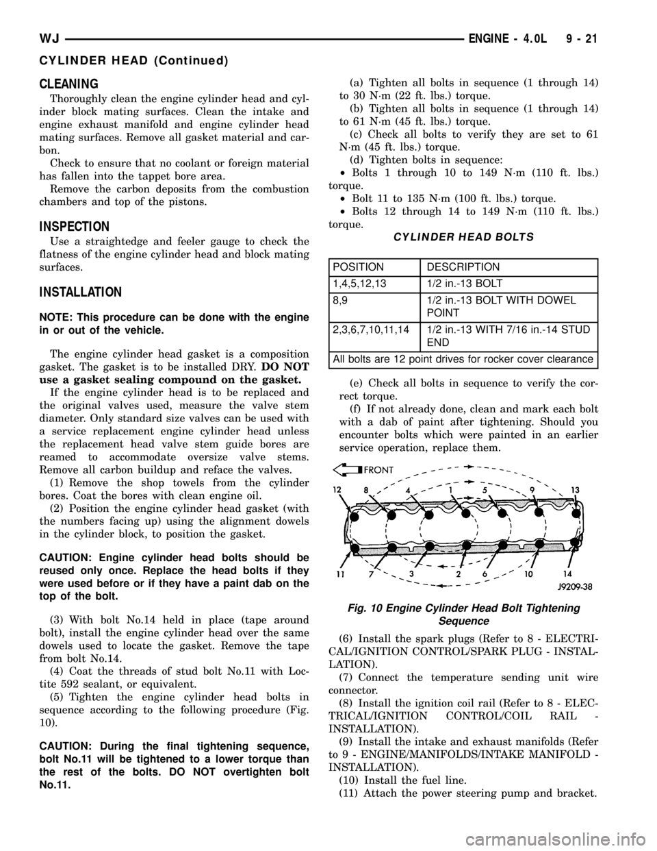
(5) Tighten the engine cylinder head bolts in
sequence according to the following procedure (Fig.
10).
CAUTION: During the final tightening sequence,
bolt No.11 will be tightened to a lower torque than
the rest of the bolts. DO NOT overtighten bolt
No.11.(a) Tighten all bolts in sequence (1 through 14)
to 30 N´m (22 ft. lbs.) torque.
(b) Tighten all bolts in sequence (1 through 14)
to 61 N´m (45 ft. lbs.) torque.
(c) Check all bolts to verify they are set to 61
N´m (45 ft. lbs.) torque.
(d) Tighten bolts in sequence:
²Bolts 1 through 10 to 149 N´m (110 ft. lbs.)
torque.
²Bolt 11 to 135 N´m (100 ft. lbs.) torque.
²Bolts 12 through 14 to 149 N´m (110 ft. lbs.)
torque.
CYLINDER HEAD BOLTS
POSITION DESCRIPTION
1,4,5,12,13 1/2 in.-13 BOLT
8,9 1/2 in.-13 BOLT WITH DOWEL
POINT
2,3,6,7,10,11,14 1/2 in.-13 WITH 7/16 in.-14 STUD
END
All bolts are 12 point drives for rocker cover clearance
(e) Check all bolts in sequence to verify the cor-
rect torque.
(f) If not already done, clean and mark each bolt
with a dab of paint after tightening. Should you
encounter bolts which were painted in an earlier
service operation, replace them.
(6) Install the spark plugs (Refer to 8 - ELECTRI-
CAL/IGNITION CONTROL/SPARK PLUG - INSTAL-
LATION).
(7) Connect the temperature sending unit wire
connector.
(8) Install the ignition coil rail (Refer to 8 - ELEC-
TRICAL/IGNITION CONTROL/COIL RAIL -
INSTALLATION).
(9) Install the intake and exhaust manifolds (Refer
to 9 - ENGINE/MANIFOLDS/INTAKE MANIFOLD -
INSTALLATION).
(10) Install the fuel line.
(11) Attach the power steering pump and bracket.
Fig. 10 Engine Cylinder Head Bolt Tightening
Sequence
WJENGINE - 4.0L 9 - 21
CYLINDER HEAD (Continued)
Page 1271 of 2199
VALVE SPRINGS
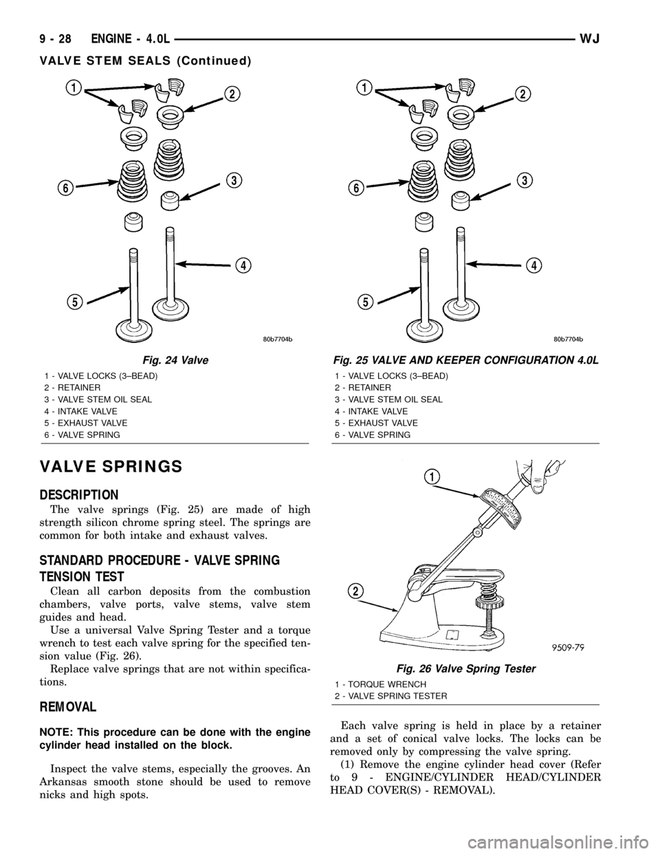
DESCRIPTION
The valve springs (Fig. 25) are made of high
strength silicon chrome spring steel. The springs are
common for both intake and exhaust valves.
STANDARD PROCEDURE - VALVE SPRING
TENSION TEST
Clean all carbon deposits from the combustion
chambers, valve ports, valve stems, valve stem
guides and head.
Use a universal Valve Spring Tester and a torque
wrench to test each valve spring for the specified ten-
sion value (Fig. 26).
Replace valve springs that are not within specifica-
tions.
REMOVAL
NOTE: This procedure can be done with the engine
cylinder head installed on the block.
Inspect the valve stems, especially the grooves. An
Arkansas smooth stone should be used to remove
nicks and high spots.Each valve spring is held in place by a retainer
and a set of conical valve locks. The locks can be
removed only by compressing the valve spring.
(1) Remove the engine cylinder head cover (Refer
to 9 - ENGINE/CYLINDER HEAD/CYLINDER
HEAD COVER(S) - REMOVAL).
Fig. 24 Valve
1 - VALVE LOCKS (3±BEAD)
2 - RETAINER
3 - VALVE STEM OIL SEAL
4 - INTAKE VALVE
5 - EXHAUST VALVE
6 - VALVE SPRING
Fig. 25 VALVE AND KEEPER CONFIGURATION 4.0L
1 - VALVE LOCKS (3±BEAD)
2 - RETAINER
3 - VALVE STEM OIL SEAL
4 - INTAKE VALVE
5 - EXHAUST VALVE
6 - VALVE SPRING
Fig. 26 Valve Spring Tester
1 - TORQUE WRENCH
2 - VALVE SPRING TESTER
9 - 28 ENGINE - 4.0LWJ
VALVE STEM SEALS (Continued)