2002 JEEP GRAND CHEROKEE rings
[x] Cancel search: ringsPage 1284 of 2199
(e) If end play is not within specification, inspect
crankshaft thrust faces for wear. If no wear is
apparent, replace the thrust bearing and measure
end play. If end play is still not within specifica-
tion, replace the crankshaft.
(11) If the crankshaft was removed, install the
crankshaft into the cylinder block.
(12) Install main bearing cap brace tighten nuts to
47 N´m (35 ft. lbs.) torque.
(13) Install oil pump assy. and tighten attaching
bolts to 23 N´m (17 ft. lbs.)
(14) Install the oil pan (Refer to 9 - ENGINE/LU-
BRICATION/OIL PAN - INSTALLATION).
(15) Install the drain plug. Tighten the plug to 34
N´m (25 ft. lbs.) torque.
(16) Lower the vehicle.
(17) Install the spark plugs. Tighten the plugs to
37 N´m (27 ft. lbs.) torque.
(18) Fill the oil pan with engine oil to the full
mark on the dipstick level.
(19) Connect negative cable to battery.
CRANKSHAFT OIL SEAL -
FRONT
REMOVAL
This procedure is done with the timing case cover
installed.
(1) Disconnect negative cable from battery.
(2) Remove the serpentine drive belt (Refer to 7 -
COOLING/ACCESSORY DRIVE/DRIVE BELTS -
REMOVAL).(3) Remove the vibration damper (Refer to 9 -
ENGINE/ENGINE BLOCK/VIBRATION DAMPER -
REMOVAL).
(4) Remove the radiator shroud.
(5) Carefully remove the oil seal. Make sure seal
bore is clean.
INSTALLATION
This procedure is done with the timing case cover
installed.
(1) Position the replacement oil seal on Timing
Case Cover Alignment and Seal Installation Tool
6139 with seal open end facing inward. Apply a light
film of Perfect Seal, or equivalent, on the outside
diameter of the seal. Lightly coat the crankshaft with
engine oil.
(2) Position the tool and seal over the end of the
crankshaft and insert a draw screw tool into Seal
Installation Tool 6139 (Fig. 50). Tighten the nut
against the tool until it contacts the cover.
(3) Remove the tools. Apply a light film of engine
oil on the vibration damper hub contact surface of
the seal.
(4) Apply MopartSilicone Rubber Adhesive Seal-
ant to the keyway in the crankshaft and insert the
key. With the key inserted in the keyway in the
crankshaft, install the vibration damper (Refer to 9 -
ENGINE/ENGINE BLOCK/VIBRATION DAMPER -
INSTALLATION).
(5) Install the serpentine belt (Refer to 7 - COOL-
ING/ACCESSORY DRIVE/DRIVE BELTS - INSTAL-
LATION).
(6) Install the radiator shroud.
(7) Connect negative cable to battery.
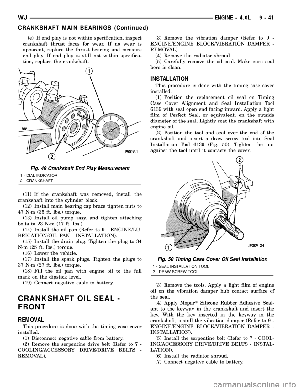
Fig. 49 Crankshaft End Play Measurement
1 - DIAL INDICATOR
2 - CRANKSHAFT
Fig. 50 Timing Case Cover Oil Seal Installation
1 - SEAL INSTALLATION TOOL
2 - DRAW SCREW TOOL
WJENGINE - 4.0L 9 - 41
CRANKSHAFT MAIN BEARINGS (Continued)
Page 1288 of 2199
PISTON SIZE CHART
CYLINDER BORE SIZE PISTON LETTER SIZE
98.438 - 98.448 mm
(3.8755 - 3.8759 in.)A
98.448 - 98.458 mm
(3.8759 - 3.8763 in.)B
98.458 - 98.468 mm
(3.8763 - 3.8767 in.)C
98.468 - 98.478 mm
(3.8767 - 3.8771 in.)D
98.478 - 98.488 mm
(3.8771 - 3.8775 in.)E
98.488 - 98.498 mm
(3.8775 - 3.8779 in.)F
REMOVAL
(1) Remove the engine cylinder head cover. (Refer
to 9 - ENGINE/CYLINDER HEAD/CYLINDER
HEAD COVER(S) - REMOVAL).
(2) Remove the rocker arms, bridges and pivots.
(3) Remove the push rods.
(4) Remove the engine cylinder head. (Refer to 9 -
ENGINE/CYLINDER HEAD - REMOVAL).
(5) Position the pistons one at a time near the bot-
tom of the stroke. Use a ridge reamer to remove theridge from the top end of the cylinder walls. Use a
protective cloth to collect the cuttings.
(6) Raise the vehicle.
(7) Drain the engine oil.
(8) Remove the oil pan and gasket. (Refer to 9 -
ENGINE/LUBRICATION/OIL PAN - REMOVAL).
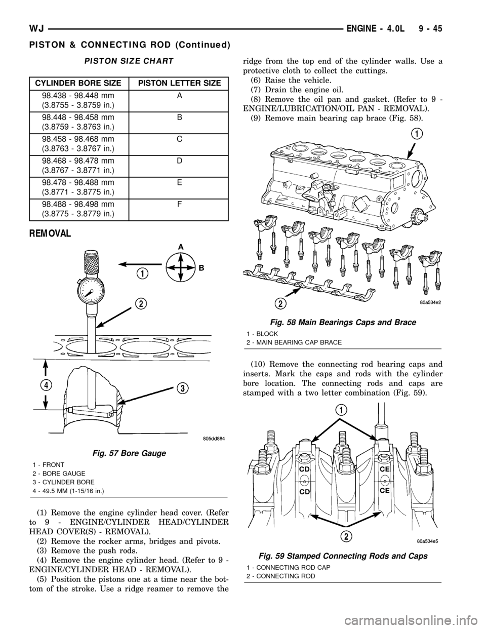
(9) Remove main bearing cap brace (Fig. 58).
(10) Remove the connecting rod bearing caps and
inserts. Mark the caps and rods with the cylinder
bore location. The connecting rods and caps are
stamped with a two letter combination (Fig. 59).
Fig. 57 Bore Gauge
1 - FRONT
2 - BORE GAUGE
3 - CYLINDER BORE
4 - 49.5 MM (1-15/16 in.)
Fig. 58 Main Bearings Caps and Brace
1 - BLOCK
2 - MAIN BEARING CAP BRACE
Fig. 59 Stamped Connecting Rods and Caps
1 - CONNECTING ROD CAP
2 - CONNECTING ROD
WJENGINE - 4.0L 9 - 45
PISTON & CONNECTING ROD (Continued)
Page 1289 of 2199

(11) Lower the vehicle until it is about 2 feet from
the floor.
CAUTION: Ensure that the connecting rod bolts DO
NOT scratch the crankshaft journals or cylinder
walls. Short pieces of rubber hose, slipped over the
rod bolts will provide protection during removal.
(12) Have an assistant push the piston and con-
necting rod assemblies up and through the top of the
cylinder bores (Fig. 60).
INSTALLATION
(1) Clean the cylinder bores thoroughly. Apply a
light film of clean engine oil to the bores with a clean
lint-free cloth.
(2) Install the piston rings on the pistons if
removed (Refer to 9 - ENGINE/ENGINE BLOCK/
PISTON RINGS - STANDARD PROCEDURE).
(3) Lubricate the piston and rings with clean
engine oil.
CAUTION: Ensure that connecting rod bolts DO
NOT scratch the crankshaft journals or cylinder
walls. Short pieces of rubber hose slipped over the
connecting rod bolts will provide protection during
installation.(4) Use a piston ring compressor to install the con-
necting rod and piston assemblies through the top of
the cylinder bores (Fig. 61).
(5) Ensure the arrow on the piston top points to
the front of the engine (Fig. 61).
(6) Raise the vehicle.
(7) Each bearing insert is fitted to its respective
journal to obtain the specified clearance between the
bearing and the journal. In production, the select fit
is obtained by using various-sized, color-coded bear-
ing inserts as listed in the Connecting Rod Bearing
Fitting Chart. The color code appears on the edge of
the bearing insert. The size is not stamped on inserts
used for production of engines.
(8) The rod journal is identified during the engine
production by a color-coded paint mark on the adja-
cent cheek or counterweight toward the flange (rear)
end of the crankshaft. The color codes used to indi-
cate journal sizes are listed in the Connecting Rod
Bearing Fitting Chart.
(9) When required, upper and lower bearing
inserts of different sizes may be used as a pair (refer
to Connecting Rod Bearing Fitting Chart). A stan-
dard size insert is sometimes used in combination
with a 0.025 mm (0.001 inch) undersize insert to
reduce clearance 0.013 mm (0.0005 inch).
CAUTION: DO NOT intermix bearing caps. Each
connecting rod and bearing cap are stamped with
the cylinder number. The stamp is located on a
machined surface adjacent to the oil squirt hole
that faces the camshaft side of the cylinder block.
(10) Install the connecting rod bearing caps and
inserts in the same positions as removed.
CAUTION: Verify that the oil squirt holes in the rods
face the camshaft and that the arrows on the pis-
tons face the front of the engine.
(11) Install main bearing cap brace (Fig. 58).
Tighten nuts to 47 N´m (35 ft. lbs.).
Fig. 60 Removal of Connecting Rod and Piston
Assembly
1 - PISTON
2 - CONNECTING ROD
3 - BLOCK
Fig. 61 Rod and Piston Assembly Installation
9 - 46 ENGINE - 4.0LWJ
PISTON & CONNECTING ROD (Continued)
Page 1290 of 2199
(12) Install the oil pan and gasket (Refer to 9 -
ENGINE/LUBRICATION/OIL PAN - INSTALLA-
TION).
(13) Lower the vehicle.
(14) Install the engine cylinder head (Refer to 9 -
ENGINE/CYLINDER HEAD - INSTALLATION),
push rods, rocker arms, bridges, pivots and engine
cylinder head cover(Refer to 9 - ENGINE/CYLINDER
HEAD/CYLINDER HEAD COVER(S) - INSTALLA-
TION).
(15) Fill the crankcase with engine oil.
PISTON RINGS
STANDARD PROCEDURE - PISTON RING
FITTING
(1) Carefully clean the carbon from all ring
grooves. Oil drain openings in the oil ring groove and
pin boss must be clear. DO NOT remove metal from
the grooves or lands. This will change ring-to-groove
clearances and will damage the ring-to-land seating.
(2) Be sure the piston ring grooves are free of
nicks and burrs.
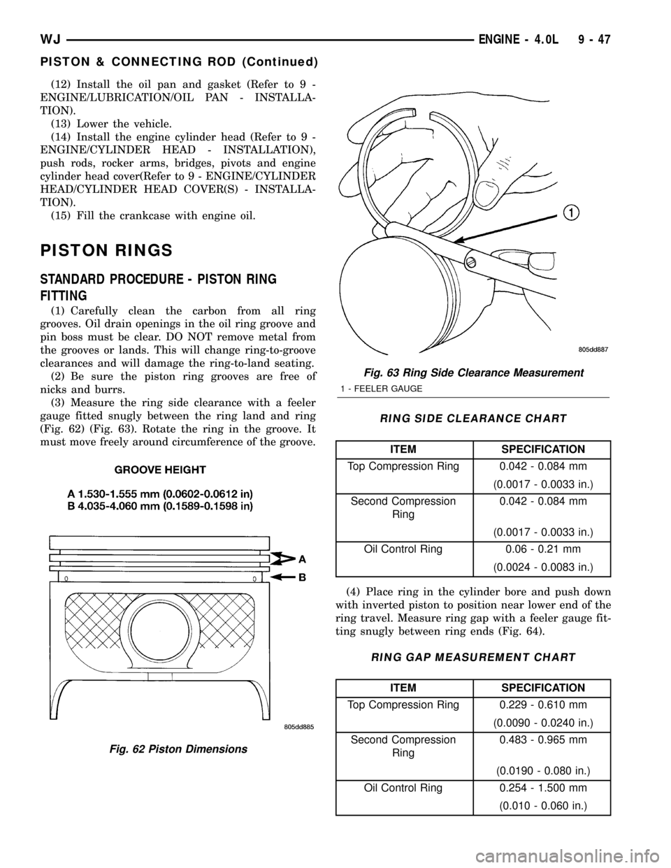
(3) Measure the ring side clearance with a feeler
gauge fitted snugly between the ring land and ring
(Fig. 62) (Fig. 63). Rotate the ring in the groove. It
must move freely around circumference of the groove.
RING SIDE CLEARANCE CHART
ITEM SPECIFICATION
Top Compression Ring 0.042 - 0.084 mm
(0.0017 - 0.0033 in.)
Second Compression
Ring0.042 - 0.084 mm
(0.0017 - 0.0033 in.)
Oil Control Ring 0.06 - 0.21 mm
(0.0024 - 0.0083 in.)
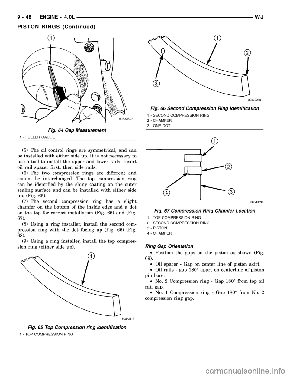
(4) Place ring in the cylinder bore and push down
with inverted piston to position near lower end of the
ring travel. Measure ring gap with a feeler gauge fit-
ting snugly between ring ends (Fig. 64).
RING GAP MEASUREMENT CHART
ITEM SPECIFICATION
Top Compression Ring 0.229 - 0.610 mm
(0.0090 - 0.0240 in.)
Second Compression
Ring0.483 - 0.965 mm
(0.0190 - 0.080 in.)
Oil Control Ring 0.254 - 1.500 mm
(0.010 - 0.060 in.)
Fig. 62 Piston Dimensions
Fig. 63 Ring Side Clearance Measurement
1 - FEELER GAUGE
WJENGINE - 4.0L 9 - 47
PISTON & CONNECTING ROD (Continued)
Page 1291 of 2199
(5) The oil control rings are symmetrical, and can
be installed with either side up. It is not necessary to
use a tool to install the upper and lower rails. Insert
oil rail spacer first, then side rails.
(6) The two compression rings are different and
cannot be interchanged. The top compression ring
can be identified by the shiny coating on the outer
sealing surface and can be installed with either side
up. (Fig. 65).
(7) The second compression ring has a slight
chamfer on the bottom of the inside edge and a dot
on the top for correct installation (Fig. 66) and (Fig.
67).
(8) Using a ring installer, install the second com-
pression ring with the dot facing up (Fig. 66) (Fig.
68).
(9) Using a ring installer, install the top compres-
sion ring (either side up).
Ring Gap Orientation
²Position the gaps on the piston as shown (Fig.
69).
²Oil spacer - Gap on center line of piston skirt.
²Oil rails - gap 180É apart on centerline of piston
pin bore.
²No. 2 Compression ring - Gap 180É from top oil
rail gap.
²No. 1 Compression ring - Gap 180É from No. 2
compression ring gap.
Fig. 64 Gap Measurement
1 - FEELER GAUGE
Fig. 65 Top Compression ring identification
1 - TOP COMPRESSION RING
Fig. 66 Second Compression Ring Identification
1 - SECOND COMPRESSION RING
2 - CHAMFER
3 - ONE DOT
Fig. 67 Compression Ring Chamfer Location
1 - TOP COMPRESSION RING
2 - SECOND COMPRESSION RING
3 - PISTON
4 - CHAMFER
9 - 48 ENGINE - 4.0LWJ
PISTON RINGS (Continued)
Page 1292 of 2199
VIBRATION DAMPER
REMOVAL
(1) Disconnect negative cable from battery.
(2) Remove the serpentine drive belt (Refer to 7 -
COOLING/ACCESSORY DRIVE/DRIVE BELTS -
REMOVAL) and fan shroud.
(3) Remove the vibration damper retaining bolt
and washer.
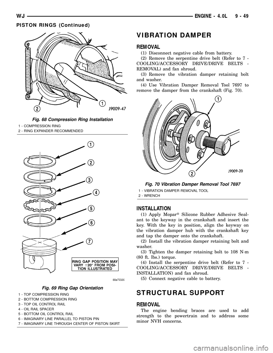
(4) Use Vibration Damper Removal Tool 7697 to
remove the damper from the crankshaft (Fig. 70).
INSTALLATION
(1) Apply MopartSilicone Rubber Adhesive Seal-
ant to the keyway in the crankshaft and insert the
key. With the key in position, align the keyway on
the vibration damper hub with the crankshaft key
and tap the damper onto the crankshaft.
(2) Install the vibration damper retaining bolt and
washer.
(3) Tighten the damper retaining bolt to 108 N´m
(80 ft. lbs.) torque.
(4) Install the serpentine drive belt (Refer to 7 -
COOLING/ACCESSORY DRIVE/DRIVE BELTS -
INSTALLATION) and fan shroud.
(5) Connect negative cable to battery.
STRUCTURAL SUPPORT
REMOVAL
The engine bending braces are used to add
strength to the powertrain and to address some
minor NVH concerns.
Fig. 68 Compression Ring Installation
1 - COMPRESSION RING
2 - RING EXPANDER RECOMMENDED
Fig. 69 Ring Gap Orientation
1 - TOP COMPRESSION RING
2 - BOTTOM COMPRESSION RING
3 - TOP OIL CONTROL RAIL
4 - OIL RAIL SPACER
5 - BOTTOM OIL CONTROL RAIL
6 - IMAGINARY LINE PARALLEL TO PISTON PIN
7 - IMAGINARY LINE THROUGH CENTER OF PISTON SKIRT
Fig. 70 Vibration Damper Removal Tool 7697
1 - VIBRATION DAMPER REMOVAL TOOL
2 - WRENCH
WJENGINE - 4.0L 9 - 49
PISTON RINGS (Continued)
Page 1304 of 2199

ENGINE - 4.7L
TABLE OF CONTENTS
page page
ENGINE - 4.7L
DESCRIPTIONÐ4.7L ENGINE.............63
DIAGNOSIS AND TESTING
DIAGNOSIS AND TESTING - ENGINE
DIAGNOSIS - INTRODUCTION...........64
DIAGNOSIS AND TESTING - ENGINE
DIAGNOSIS - PERFORMANCE...........65
DIAGNOSIS AND TESTING - ENGINE
DIAGNOSIS - MECHANICAL.............66
DIAGNOSIS AND TESTING - ENGINE
DIAGNOSIS - LUBRICATION.............67
DIAGNOSIS AND TESTING - CYLINDER
COMPRESSION PRESSURE.............68
DIAGNOSIS AND TESTING - CYLINDER
COMBUSTION PRESSURE LEAKAGE......69
STANDARD PROCEDURE
STANDARD PROCEDURE - REPAIR
DAMAGED OR WORN THREADS.........70
STANDARD PROCEDURE - FORM-IN-
PLACE GASKETS AND SEALERS.........70
STANDARD PROCEDURE - ENGINE
GASKET SURFACE PREPARATION........70
STANDARD PROCEDURE - ENGINE CORE
AND OIL GALLERY PLUGS..............71
REMOVAL.............................71
INSTALLATION.........................73
SPECIFICATIONS
4.7L ENGINE.........................74
SPECIFICATIONS - 4.7L H.O. ENGINE.....77
TORQUE............................79
SPECIAL TOOLS
4.7L ENGINE.........................80
AIR CLEANER ELEMENT
REMOVAL - 4.7L........................83
INSTALLATION - 4.7L....................83
AIR CLEANER HOUSING
REMOVAL - 4.7L........................84
INSTALLATION - 4.7L....................84
CYLINDER HEAD - LEFT
DESCRIPTION
DESCRIPTION - CYLINDER HEAD........84
DESCRIPTION - VALVE GUIDES..........84
DIAGNOSIS AND TESTING
DIAGNOSIS AND TESTING - HYDRAULIC
LASH ADJUSTER.....................84
DIAGNOSIS AND TESTINGÐCYLINDER
HEAD GASKET.......................85
REMOVAL.............................85
CLEANING............................86
INSPECTION..........................87INSTALLATION.........................87
CAMSHAFT(S) - LEFT
DESCRIPTION.........................88
REMOVAL.............................89
INSTALLATION.........................90
CYLINDER HEAD COVER(S) - LEFT
DESCRIPTION.........................93
REMOVAL - LEFT SIDE..................93
CLEANING............................93
INSTALLATIONÐLEFT SIDE...............93
INTAKE/EXHAUST VALVES & SEATS
DESCRIPTION.........................94
STANDARD PROCEDUREÐREFACING......94
REMOVAL.............................94
INSTALLATION.........................95
ROCKER ARM / ADJUSTER ASSEMBLY
DESCRIPTION.........................96
REMOVAL.............................96
INSTALLATION.........................96
VALVE SPRINGS
DESCRIPTION.........................97
VALVE STEM SEALS
DESCRIPTION.........................97
CYLINDER HEAD - RIGHT
DESCRIPTION
DESCRIPTION - CYLINDER HEAD........97
DESCRIPTION - VALVE GUIDES..........97
DIAGNOSIS AND TESTING
DIAGNOSIS AND TESTINGÐCYLINDER
HEAD GASKET.......................97
DIAGNOSIS AND TESTING - HYDRAULIC
LASH ADJUSTER.....................98
REMOVAL.............................98
CLEANING............................99
INSPECTION..........................99
INSTALLATION.........................99
CAMSHAFT(S) - RIGHT
DESCRIPTION........................100
REMOVAL............................100
INSTALLATION........................102
CYLINDER HEAD COVER(S) - RIGHT
DESCRIPTION........................104
REMOVAL - RIGHT SIDE................104
CLEANING...........................104
INSTALLATION - RIGHT SIDE.............104
INTAKE/EXHAUST VALVES & SEATS
DESCRIPTION........................104
STANDARD PROCEDUREÐREFACING.....105
REMOVAL............................105
INSTALLATION........................106
WJENGINE - 4.7L 9 - 61
Page 1305 of 2199

ROCKER ARM / ADJUSTER ASSEMBLY
DESCRIPTION........................107
REMOVAL............................107
INSTALLATION........................107
VALVE SPRINGS
DESCRIPTION........................108
VALVE STEM SEALS
DESCRIPTION........................108
ENGINE BLOCK
DESCRIPTION........................108
STANDARD PROCEDUREÐCYLINDER BORE
HONING...........................108
CLEANING...........................109
INSPECTION.........................109
CONNECTING ROD BEARINGS
STANDARD PROCEDURE - CONNECTING
ROD BEARING FITTING...............109
CRANKSHAFT
DESCRIPTION........................111
STANDARD PROCEDURE - MEASURING
CRANKSHAFT END PLAY..............111
REMOVAL............................112
INSPECTION..........................112
INSTALLATION........................112
CRANKSHAFT MAIN BEARINGS
STANDARD PROCEDUREÐCRANKSHAFT
MAIN BEARING - FITTING..............114
INSPECTION..........................115
CRANKSHAFT OIL SEAL - FRONT
REMOVAL............................115
INSTALLATION........................116
CRANKSHAFT OIL SEAL - REAR
REMOVAL............................117
INSTALLATION........................117
FLEX PLATE
REMOVAL............................118
INSTALLATION........................118
PISTON & CONNECTING ROD
DESCRIPTION........................118
STANDARD PROCEDUREÐPISTON FITTING . 118
REMOVAL............................118
CLEANING...........................119
INSPECTION..........................119
INSTALLATION........................120
PISTON RINGS
STANDARD PROCEDURE - PISTON RING
FITTING............................121
VIBRATION DAMPER
REMOVAL............................122
INSTALLATION........................123
STRUCTURAL COVER
DESCRIPTION........................124
OPERATION..........................124
REMOVAL............................124
INSTALLATION........................124
FRONT MOUNT
REMOVAL............................124INSTALLATION........................125
REAR MOUNT
REMOVAL............................125
INSTALLATION........................126
LUBRICATION
DESCRIPTION........................126
OPERATION..........................126
DIAGNOSIS AND TESTING
DIAGNOSIS AND TESTINGÐENGINE OIL
PRESSURE.........................128
DIAGNOSIS AND TESTINGÐREAR SEAL
AREA LEAKS........................128
DIAGNOSIS AND TESTINGÐENGINE OIL
LEAK..............................129
OIL
STANDARD PROCEDURE - ENGINE OIL....130
OIL FILTER
REMOVAL............................131
INSTALLATION........................132
OIL PAN
DESCRIPTION........................132
REMOVAL............................132
CLEANING...........................132
INSPECTION.........................132
INSTALLATION........................132
OIL PRESSURE SENSOR/SWITCH
DESCRIPTION........................133
OPERATION..........................133
REMOVAL............................133
INSTALLATION........................133
OIL PUMP
REMOVAL............................134
DISASSEMBLY........................134
CLEANING...........................134
INSPECTION.........................134
ASSEMBLY...........................135
INSTALLATION........................135
INTAKE MANIFOLD
DESCRIPTION........................136
DIAGNOSIS AND TESTINGÐINTAKE
MANIFOLD LEAKAGE.................136
REMOVAL............................136
CLEANING...........................137
INSPECTION.........................137
INSTALLATION........................137
EXHAUST MANIFOLD - LEFT
DESCRIPTION........................138
REMOVAL............................138
CLEANING...........................138
INSPECTION.........................138
INSTALLATION........................138
EXHAUST MANIFOLD - RIGHT
DESCRIPTION........................139
REMOVAL............................139
CLEANING...........................140
INSPECTION.........................141
INSTALLATION........................141
9 - 62 ENGINE - 4.7LWJ