2002 JEEP GRAND CHEROKEE Drb scan tool
[x] Cancel search: Drb scan toolPage 1430 of 2199
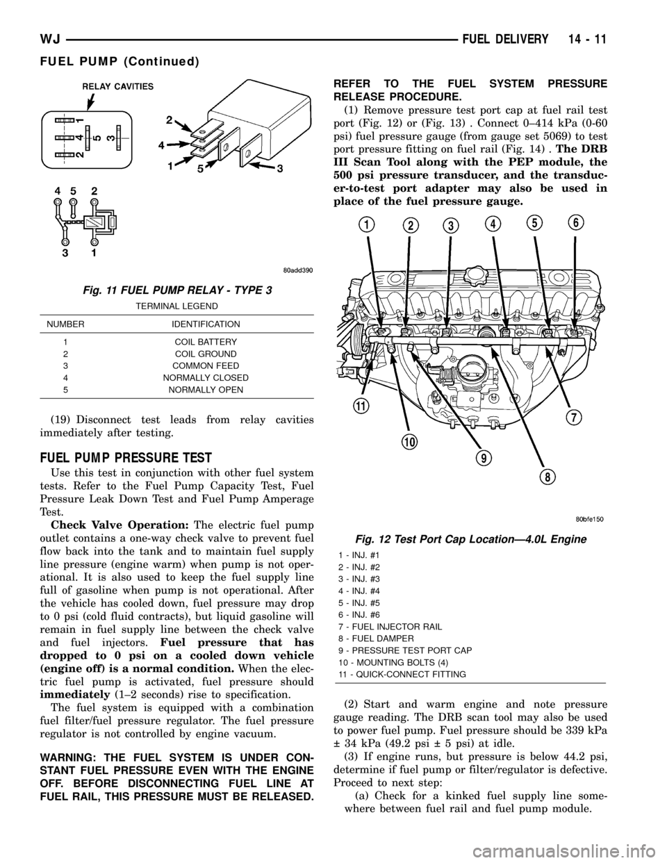
(19) Disconnect test leads from relay cavities
immediately after testing.
FUEL PUMP PRESSURE TEST
Use this test in conjunction with other fuel system
tests. Refer to the Fuel Pump Capacity Test, Fuel
Pressure Leak Down Test and Fuel Pump Amperage
Test.
Check Valve Operation:The electric fuel pump
outlet contains a one-way check valve to prevent fuel
flow back into the tank and to maintain fuel supply
line pressure (engine warm) when pump is not oper-
ational. It is also used to keep the fuel supply line
full of gasoline when pump is not operational. After
the vehicle has cooled down, fuel pressure may drop
to 0 psi (cold fluid contracts), but liquid gasoline will
remain in fuel supply line between the check valve
and fuel injectors.Fuel pressure that has
dropped to 0 psi on a cooled down vehicle
(engine off) is a normal condition.When the elec-
tric fuel pump is activated, fuel pressure should
immediately(1±2 seconds) rise to specification.
The fuel system is equipped with a combination
fuel filter/fuel pressure regulator. The fuel pressure
regulator is not controlled by engine vacuum.
WARNING: THE FUEL SYSTEM IS UNDER CON-
STANT FUEL PRESSURE EVEN WITH THE ENGINE
OFF. BEFORE DISCONNECTING FUEL LINE AT
FUEL RAIL, THIS PRESSURE MUST BE RELEASED.REFER TO THE FUEL SYSTEM PRESSURE
RELEASE PROCEDURE.
(1) Remove pressure test port cap at fuel rail test
port (Fig. 12) or (Fig. 13) . Connect 0±414 kPa (0-60
psi) fuel pressure gauge (from gauge set 5069) to test
port pressure fitting on fuel rail (Fig. 14) .The DRB
III Scan Tool along with the PEP module, the
500 psi pressure transducer, and the transduc-
er-to-test port adapter may also be used in
place of the fuel pressure gauge.
(2) Start and warm engine and note pressure
gauge reading. The DRB scan tool may also be used
to power fuel pump. Fuel pressure should be 339 kPa
34 kPa (49.2 psi 5 psi) at idle.
(3) If engine runs, but pressure is below 44.2 psi,
determine if fuel pump or filter/regulator is defective.
Proceed to next step:
(a) Check for a kinked fuel supply line some-
where between fuel rail and fuel pump module.
Fig. 11 FUEL PUMP RELAY - TYPE 3
TERMINAL LEGEND
NUMBER IDENTIFICATION
1 COIL BATTERY
2 COIL GROUND
3 COMMON FEED
4 NORMALLY CLOSED
5 NORMALLY OPEN
Fig. 12 Test Port Cap LocationÐ4.0L Engine
1 - INJ. #1
2 - INJ. #2
3 - INJ. #3
4 - INJ. #4
5 - INJ. #5
6 - INJ. #6
7 - FUEL INJECTOR RAIL
8 - FUEL DAMPER
9 - PRESSURE TEST PORT CAP
10 - MOUNTING BOLTS (4)
11 - QUICK-CONNECT FITTING
WJFUEL DELIVERY 14 - 11
FUEL PUMP (Continued)
Page 1432 of 2199
(e) Use DRB scan tool to power fuel pump. If
pressure is now within specifications, replace fuel
filter/fuel pressure regulator.
(f) If pressure is still low, replace fuel pump
module.
(4) If operating pressure is above 54.2 psi, electric
fuel pump is OK, but fuel pressure regulator is defec-
tive. Replace fuel filter/fuel pressure regulator.
(5) Install test port cap to fuel rail test port.
FUEL PUMP MODULE
DESCRIPTION
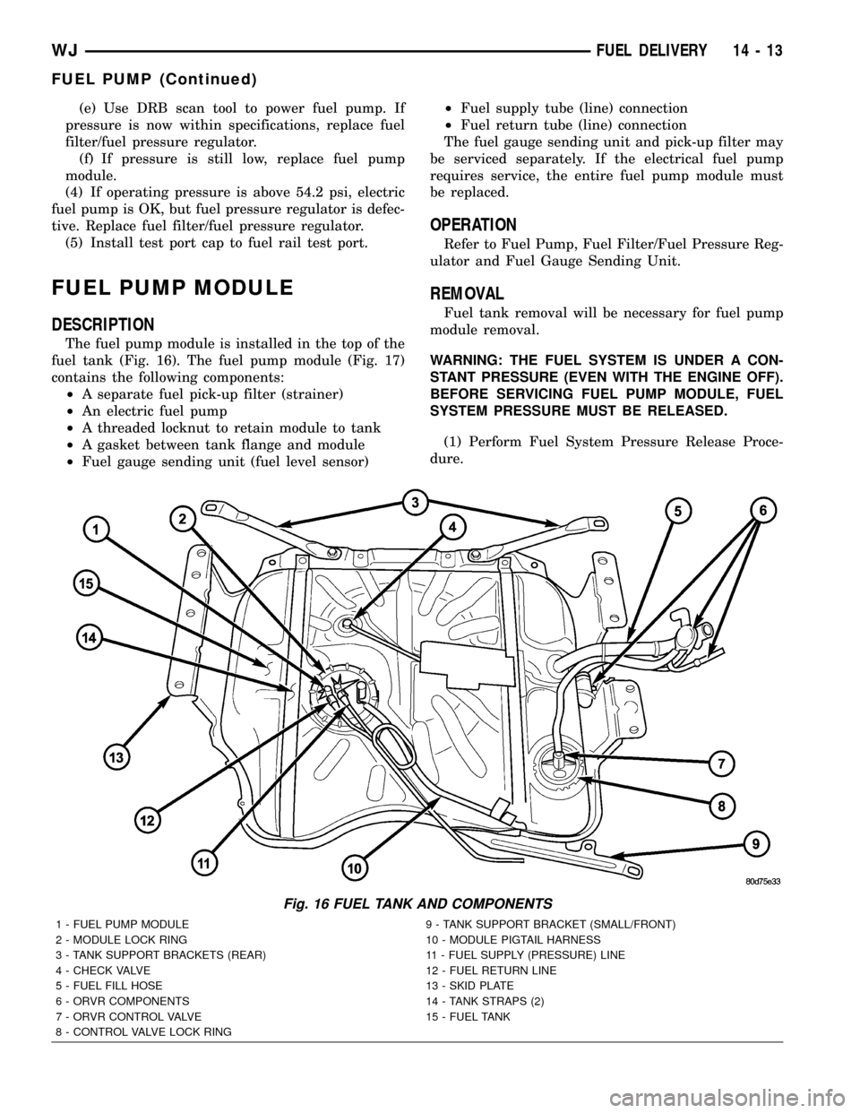
The fuel pump module is installed in the top of the
fuel tank (Fig. 16). The fuel pump module (Fig. 17)
contains the following components:
²A separate fuel pick-up filter (strainer)
²An electric fuel pump
²A threaded locknut to retain module to tank
²A gasket between tank flange and module
²Fuel gauge sending unit (fuel level sensor)²Fuel supply tube (line) connection
²Fuel return tube (line) connection
The fuel gauge sending unit and pick-up filter may
be serviced separately. If the electrical fuel pump
requires service, the entire fuel pump module must
be replaced.
OPERATION
Refer to Fuel Pump, Fuel Filter/Fuel Pressure Reg-
ulator and Fuel Gauge Sending Unit.
REMOVAL
Fuel tank removal will be necessary for fuel pump
module removal.
WARNING: THE FUEL SYSTEM IS UNDER A CON-
STANT PRESSURE (EVEN WITH THE ENGINE OFF).
BEFORE SERVICING FUEL PUMP MODULE, FUEL
SYSTEM PRESSURE MUST BE RELEASED.
(1) Perform Fuel System Pressure Release Proce-
dure.
Fig. 16 FUEL TANK AND COMPONENTS
1 - FUEL PUMP MODULE 9 - TANK SUPPORT BRACKET (SMALL/FRONT)
2 - MODULE LOCK RING 10 - MODULE PIGTAIL HARNESS
3 - TANK SUPPORT BRACKETS (REAR) 11 - FUEL SUPPLY (PRESSURE) LINE
4 - CHECK VALVE 12 - FUEL RETURN LINE
5 - FUEL FILL HOSE 13 - SKID PLATE
6 - ORVR COMPONENTS 14 - TANK STRAPS (2)
7 - ORVR CONTROL VALVE 15 - FUEL TANK
8 - CONTROL VALVE LOCK RING
WJFUEL DELIVERY 14 - 13
FUEL PUMP (Continued)
Page 1438 of 2199

(14) Install air tube (or duct) at top of throttle
body.
(15) Install fuel tank cap.
(16) Connect negative battery cable to battery.
(17) Start engine and check for fuel leaks.
FUEL TANK
DESCRIPTION
The fuel tank is constructed of a plastic material.
Its main functions are for fuel storage and for place-
ment of the fuel pump module and certain ORVR
components.
OPERATION
All models pass a full 360 degree rollover test
without fuel leakage. To accomplish this, fuel and
vapor flow controls are required for all fuel tank con-
nections.
A fuel tank check valve(s) is mounted into the top
of the fuel tank (or pump module). Refer to Fuel
Tank Check Valve for additional information.
An evaporation control system is connected to the
check valve(s) to reduce emissions of fuel vapors into
the atmosphere. When fuel evaporates from the fuel
tank, vapors pass through vent hoses or tubes to a
charcoal canister where they are temporarily held.
When the engine is running, the vapors are drawn
into the intake manifold. Certain models are also
equipped with a self-diagnosing system using a Leak
Detection Pump (LDP). Refer to Emission Control
System for additional information.
Refer to ORVR for On-Board Refueling Vapor
Recovery system information.
REMOVAL
WARNING: THE FUEL SYSTEM IS UNDER CON-
STANT FUEL PRESSURE EVEN WITH ENGINE OFF.
PRESSURE MUST BE RELEASED BEFORE SERVIC-
ING FUEL TANK.
Two different procedures may be used to drain fuel
tank (through ORVR control valve opening at top of
fuel tank, or using DRB scan tool). The quickest is
draining through ORVR control valve opening at top
of fuel tank (Fig. 26).
As an alternative procedure, the electric fuel pump
may be activated allowing tank to be drained at fuel
rail connection. Refer to DRB scan tool for fuel pump
activation procedures. Before disconnecting fuel line
at fuel rail, release fuel pressure. Refer to the Fuel
System Pressure Release Procedure for procedures.
Attach end of Special Adapter Hose Tool number
6539 at fuel rail disconnection. Position opposite end
of 6539 to an approved gasoline draining station.Activate fuel pump with DRB and drain tank until
empty.
If electric fuel pump is not operating, tankMUST
be drained through ORVR control valve opening at
top of fuel tank (Fig. 26).
(1) Release fuel system pressure. Refer to Fuel
System Pressure Release Procedure.
(2) Disconnect negative battery cable at battery.
(3) Raise and support vehicle.
(4) Remove left rear wheel/tire.
CAUTION: HANDLE EVAP, LDP AND ORVR VAPOR /
VACUUM LINES VERY CAREFULLY. THESE LINES
AND HOSES MUST BE FIRMLY CONNECTED.
CHECK THE VAPOR/VACUUM LINES AT THE LDP,
LDP FILTER, EVAP CANISTER, EVAP CANISTER
PURGE SOLENOID AND ORVR COMPONENTS FOR
DAMAGE OR LEAKS. IF A LEAK IS PRESENT, A
DIAGNOSTIC TROUBLE CODE (DTC) MAY BE SET.
(5) Clean top of fuel tank at ORVR control valve
(Fig. 26) or (Fig. 27).
(6) Press release tab in direction of arrow in (Fig.
27) and remove ORVR control valve lock ring
(counter-clockwise). Lift up ORVR control slightly.
Using an approved gasoline draining station, drain
tank until empty through this opening.
(7) Remove stone shield behind left/rear wheel
(Fig. 28). Drill out plastic rivets for removal.
(8) Remove 3 LDP mounting bolts (Fig. 29).
(9) Remove support bracket brace bolt (Fig. 30).
(10) Loosen, but do not remove 2 support bracket
nuts at frame rail (Fig. 29).
(11) To separate and lower front section of two-
piece support bracket, remove 3 attaching bolts on
bottom of support bracket (Fig. 30). While lowering
support bracket, disconnect LDP wiring clip (Fig. 31).
(12) Remove hose clamp (Fig. 32) and remove fuel
fill hose from fuel fill tube.
(13) Cut and discard tie wrap from axle vent hose
(Fig. 32).
(14) Disconnect fuel vent hose from fuel vent tube
(Fig. 32).
(15) Disconnect ORVR hose elbow (Fig. 33) at top
of EVAP canister.
(16) Place hydraulic jack to bottom of fuel tank.
(17) Remove fuel tank-to-rear bumper fascia clips
(Fig. 34).
(18) Remove fuel tank heat shield mounting bolts
(Fig. 35).
CAUTION: To protect fuel tank from exhaust heat,
shield must re-installed after tank installation.
WARNING: PLACE SHOP TOWEL AROUND FUEL
LINES TO CATCH ANY EXCESS FUEL.
WJFUEL DELIVERY 14 - 19
FUEL RAIL (Continued)
Page 1463 of 2199
The PCM determines injector on-time (pulse width)
based on various inputs.
DIAGNOSIS AND TESTING - FUEL INJECTOR
To perform a complete test of the fuel injectors and
their circuitry, use the DRB scan tool and refer to the
appropriate Powertrain Diagnostics Procedures man-
ual. To test the injector only, refer to the following:
Disconnect the fuel injector wire harness connector
from the injector. The injector is equipped with 2
electrical terminals (pins). Place an ohmmeter across
the terminals. Resistance reading should be approxi-
mately 12 ohms 1.2 ohms at 20ÉC (68ÉF).
REMOVAL
WARNING: THE FUEL SYSTEM IS UNDER CON-
STANT PRESSURE EVEN WITH ENGINE OFF.
BEFORE SERVICING FUEL INJECTOR(S), FUEL
SYSTEM PRESSURE MUST BE RELEASED.
To remove one or more fuel injectors, the fuel rail
assembly must be removed from engine.
(1) Perform Fuel System Pressure Release Proce-
dure.
(2) Remove fuel injector rail. Refer to Fuel Injector
Rail Removal/Installation.
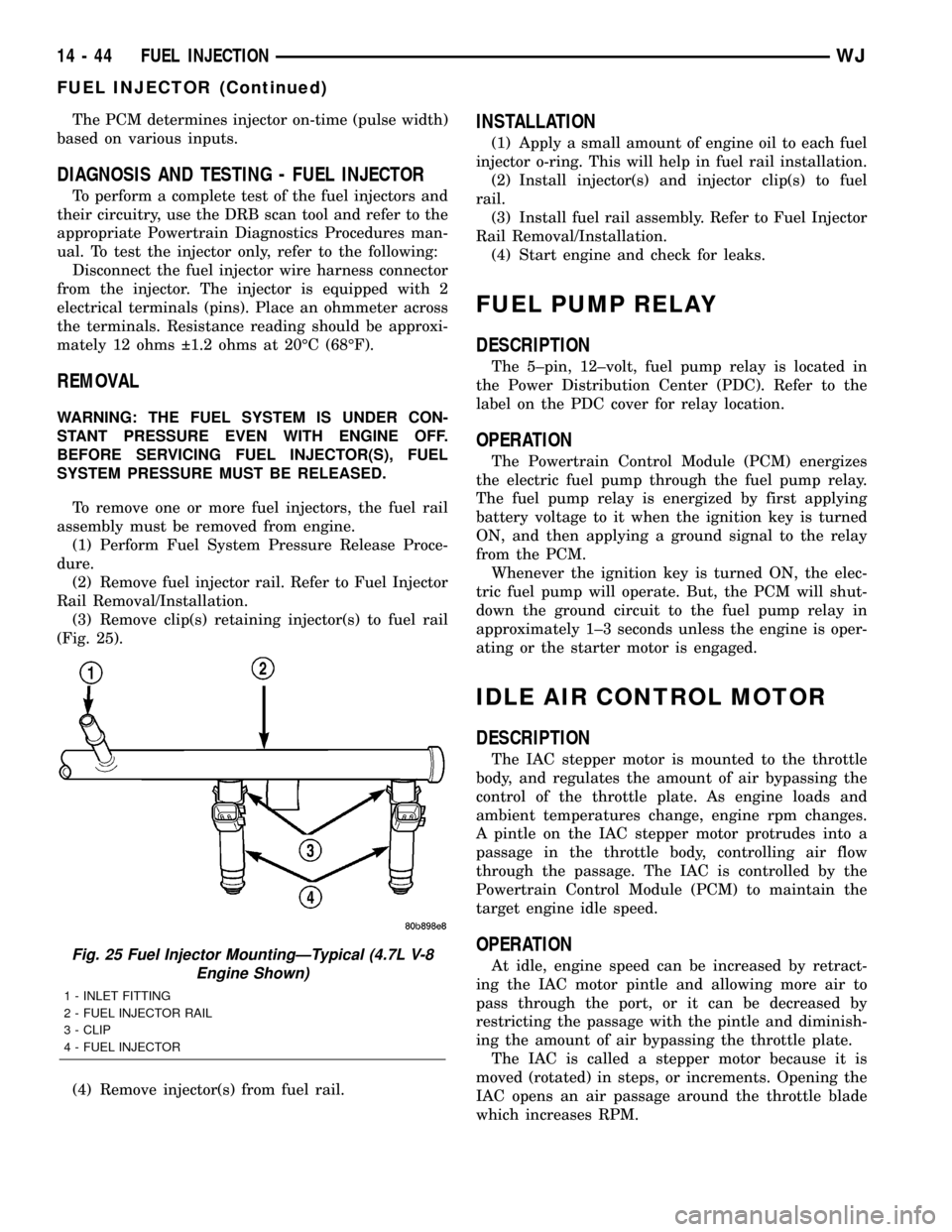
(3) Remove clip(s) retaining injector(s) to fuel rail
(Fig. 25).
(4) Remove injector(s) from fuel rail.
INSTALLATION
(1) Apply a small amount of engine oil to each fuel
injector o-ring. This will help in fuel rail installation.
(2) Install injector(s) and injector clip(s) to fuel
rail.
(3) Install fuel rail assembly. Refer to Fuel Injector
Rail Removal/Installation.
(4) Start engine and check for leaks.
FUEL PUMP RELAY
DESCRIPTION
The 5±pin, 12±volt, fuel pump relay is located in
the Power Distribution Center (PDC). Refer to the
label on the PDC cover for relay location.
OPERATION
The Powertrain Control Module (PCM) energizes
the electric fuel pump through the fuel pump relay.
The fuel pump relay is energized by first applying
battery voltage to it when the ignition key is turned
ON, and then applying a ground signal to the relay
from the PCM.
Whenever the ignition key is turned ON, the elec-
tric fuel pump will operate. But, the PCM will shut-
down the ground circuit to the fuel pump relay in
approximately 1±3 seconds unless the engine is oper-
ating or the starter motor is engaged.
IDLE AIR CONTROL MOTOR
DESCRIPTION
The IAC stepper motor is mounted to the throttle
body, and regulates the amount of air bypassing the
control of the throttle plate. As engine loads and
ambient temperatures change, engine rpm changes.
A pintle on the IAC stepper motor protrudes into a
passage in the throttle body, controlling air flow
through the passage. The IAC is controlled by the
Powertrain Control Module (PCM) to maintain the
target engine idle speed.
OPERATION
At idle, engine speed can be increased by retract-
ing the IAC motor pintle and allowing more air to
pass through the port, or it can be decreased by
restricting the passage with the pintle and diminish-
ing the amount of air bypassing the throttle plate.
The IAC is called a stepper motor because it is
moved (rotated) in steps, or increments. Opening the
IAC opens an air passage around the throttle blade
which increases RPM.Fig. 25 Fuel Injector MountingÐTypical (4.7L V-8
Engine Shown)
1 - INLET FITTING
2 - FUEL INJECTOR RAIL
3 - CLIP
4 - FUEL INJECTOR
14 - 44 FUEL INJECTIONWJ
FUEL INJECTOR (Continued)
Page 1491 of 2199

KEY-IN IGNITION SWITCH
DESCRIPTION
The key-in ignition switch is concealed within and
integral to the ignition switch, which is mounted on
the steering column. The key-in ignition switch is
actuated by the ignition lock cylinder mechanism,
and is hard wired between a body ground and the
Body Control Module (BCM) through the instrument
panel wire harness.
The key-in ignition switch cannot be adjusted or
repaired and, if faulty or damaged, the entire igni-
tion switch unit must be replaced,(Refer to 19 -
STEERING/COLUMN/LOCK CYLINDER HOUSING
- REMOVAL). For complete circuit diagrams, refer to
Body Control Modulein the Contents of Wiring
Diagrams.
OPERATION
The key-in ignition switch closes a path to ground
for the BCM when the ignition key is inserted in the
ignition lock cylinder, and opens the ground path
when the key is removed from the ignition lock cyl-
inder. The BCM monitors the key-in ignition switch
status through an internal pull-up, then sends the
proper switch status messages to other electronic
modules over the Programmable Communications
Interface (PCI) data bus network. The key-in ignition
switch status is also used by the BCM as an input
for chime warning system operation.
DIAGNOSIS AND TESTING
KEY-IN IGNITION SWITCH
For complete circuit diagrams, refer toBody Con-
trol Modulein the Contents of Wiring Diagrams.
WARNING: ON VEHICLES EQUIPPED WITH AIR-
BAGS, REFER TO GROUP 8M - PASSIVE
RESTRAINT SYSTEMS BEFORE ATTEMPTING ANY
STEERING WHEEL, STEERING COLUMN, OR
INSTRUMENT PANEL COMPONENT DIAGNOSIS OR
SERVICE. FAILURE TO TAKE THE PROPER PRE-
CAUTIONS COULD RESULT IN ACCIDENTAL AIR-
BAG DEPLOYMENT AND POSSIBLE PERSONAL
INJURY.(1) Disconnect and isolate the battery negative
cable. Disconnect the instrument panel wire harness
connector from the key-in ignition switch connector
receptacle on the ignition switch. Check for continu-
ity between the key-in ignition switch sense and
ground terminals of the key-in ignition switch con-
nector receptacle. There should be continuity with
the key inserted in the ignition lock cylinder, and no
continuity with the key removed from the ignition
lock cylinder. If OK, go to Step 2. If not OK, replace
the faulty ignition switch unit.
(2) Check for continuity between the ground cir-
cuit cavity of the instrument panel wire harness con-
nector for the key-in ignition switch and a good
ground. There should be continuity. If OK, go to Step
3. If not OK, repair the open ground circuit to ground
as required.
(3) Disconnect the gray 26-way instrument panel
wire harness connector from the Body Control Mod-
ule (BCM) connector receptacle. Check for continuity
between the key-in ignition switch sense circuit cav-
ity of the instrument panel wire harness connector
for the key-in ignition switch and a good ground.
There should be no continuity. If OK, go to Step 4. If
not OK, repair the shorted key-in ignition switch
sense circuit as required.
(4) Check for continuity between the key-in igni-
tion switch sense circuit cavities of the instrument
panel wire harness connector for the key-in ignition
switch and the gray 26-way instrument panel wire
harness connector for the BCM. There should be con-
tinuity. If OK, use a DRB scan tool and the proper
Diagnostic Procedures manual to test the BCM. If
not OK, repair the open key-in ignition switch sense
circuit as required.
LOCK CYLINDER
REMOVAL
The ignition key must be in the key cylinder for
cylinder removal. The key cylinder must be removed
first before removing ignition switch.
(1) Disconnect negative battery cable at battery.
(2) If equipped with an automatic transmission,
place shifter in PARK position.
(3) Rotate key to ON position.
19 - 14 COLUMNWJ
Page 1530 of 2199

FOURTH GEAR POWERFLOW
Fourth gear overdrive range is electronically con-
trolled and hydraulically activated. Various sensor
inputs are supplied to the powertrain control module
to operate the overdrive solenoid on the valve body.
The solenoid contains a check ball that opens and
closes a vent port in the 3-4 shift valve feed passage.
The overdrive solenoid (and check ball) are not ener-
gized in first, second, third, or reverse gear. The vent
port remains open, diverting line pressure from the
2-3 shift valve away from the 3-4 shift valve. The
overdrive control switch must be in the ON position
to transmit overdrive status to the PCM. A 3-4
upshift occurs only when the overdrive solenoid is
energized by the PCM. The PCM energizes the over-
drive solenoid during the 3-4 upshift. This causes the
solenoid check ball to close the vent port allowing
line pressure from the 2-3 shift valve to act directly
on the 3-4 upshift valve. Line pressure on the 3-4
shift valve overcomes valve spring pressure moving
the valve to the upshift position. This action exposes
the feed passages to the 3-4 timing valve, 3-4 quick
fill valve, 3-4 accumulator, and ultimately to the
overdrive piston. Line pressure through the timing
valve moves the overdrive piston into contact with
the overdrive clutch. The direct clutch is disengaged
before the overdrive clutch is engaged. The boost
valve provides increased fluid apply pressure to the
overdrive clutch during 3-4 upshifts, and when accel-
erating in fourth gear. The 3-4 accumulator cushions
overdrive clutch engagement to smooth 3-4 upshifts.
The accumulator is charged at the same time as
apply pressure acts against the overdrive piston.
DIAGNOSIS AND TESTING
DIAGNOSIS AND TESTING - AUTOMATIC
TRANSMISSION
Automatic transmission problems can be a result of
poor engine performance, incorrect fluid level, incor-
rect linkage or cable adjustment, band or hydraulic
control pressure adjustments, hydraulic system mal-
functions or electrical/mechanical component mal-
functions. Begin diagnosis by checking the easily
accessible items such as: fluid level and condition,
linkage adjustments and electrical connections. A
road test will determine if further diagnosis is neces-
sary.
DIAGNOSIS AND TESTING - PRELIMINARY
Two basic procedures are required. One procedure
for vehicles that are drivable and an alternate proce-
dure for disabled vehicles (will not back up or move
forward).
VEHICLE IS DRIVEABLE
(1) Check for transmission fault codes using DRBt
scan tool.
(2) Check fluid level and condition.
(3) Adjust throttle and gearshift linkage if com-
plaint was based on delayed, erratic, or harsh shifts.
(4) Road test and note how transmission upshifts,
downshifts, and engages.
(5) Perform hydraulic pressure test if shift prob-
lems were noted during road test.
(6) Perform air-pressure test to check clutch-band
operation.
VEHICLE IS DISABLED
(1) Check fluid level and condition.
(2) Check for broken or disconnected gearshift or
throttle linkage.
(3) Check for cracked, leaking cooler lines, or loose
or missing pressure-port plugs.
(4) Raise and support vehicle on safety stands,
start engine, shift transmission into gear, and note
following:
(a) If propeller shaft turns but wheels do not,
problem is with differential or axle shafts.
(b) If propeller shaft does not turn and transmis-
sion is noisy, stop engine. Remove oil pan, and
check for debris. If pan is clear, remove transmis-
sion and check for damaged drive plate, converter,
oil pump, or input shaft.
(c) If propeller shaft does not turn and transmis-
sion is not noisy, perform hydraulic-pressure test to
determine if problem is hydraulic or mechanical.
DIAGNOSIS AND TESTING - ROAD TESTING
Before road testing, be sure the fluid level and con-
trol cable adjustments have been checked and
adjusted if necessary. Verify that diagnostic trouble
codes have been resolved.
Observe engine performance during the road test.
A poorly tuned engine will not allow accurate analy-
sis of transmission operation.
Operate the transmission in all gear ranges. Check
for shift variations and engine flare which indicates
slippage. Note if shifts are harsh, spongy, delayed,
early, or if part throttle downshifts are sensitive.
Slippage indicated by engine flare, usually means
clutch, band or overrunning clutch problems. If the
condition is advanced, an overhaul will be necessary
to restore normal operation.
A slipping clutch or band can often be determined
by comparing which internal units are applied in the
various gear ranges. The Clutch and Band Applica-
tion chart provides a basis for analyzing road test
results.
WJAUTOMATIC TRANSMISSION - 42RE 21 - 11
AUTOMATIC TRANSMISSION - 42RE (Continued)
Page 1536 of 2199
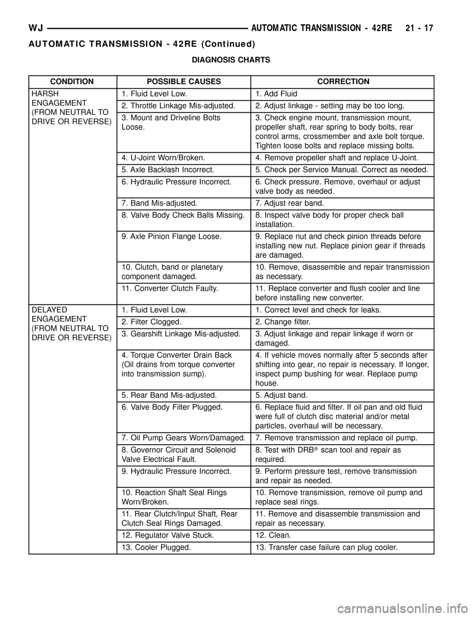
DIAGNOSIS CHARTS
CONDITION POSSIBLE CAUSES CORRECTION
HARSH
ENGAGEMENT
(FROM NEUTRAL TO
DRIVE OR REVERSE)1. Fluid Level Low. 1. Add Fluid
2. Throttle Linkage Mis-adjusted. 2. Adjust linkage - setting may be too long.
3. Mount and Driveline Bolts
Loose.3. Check engine mount, transmission mount,
propeller shaft, rear spring to body bolts, rear
control arms, crossmember and axle bolt torque.
Tighten loose bolts and replace missing bolts.
4. U-Joint Worn/Broken. 4. Remove propeller shaft and replace U-Joint.
5. Axle Backlash Incorrect. 5. Check per Service Manual. Correct as needed.
6. Hydraulic Pressure Incorrect. 6. Check pressure. Remove, overhaul or adjust
valve body as needed.
7. Band Mis-adjusted. 7. Adjust rear band.
8. Valve Body Check Balls Missing. 8. Inspect valve body for proper check ball
installation.
9. Axle Pinion Flange Loose. 9. Replace nut and check pinion threads before
installing new nut. Replace pinion gear if threads
are damaged.
10. Clutch, band or planetary
component damaged.10. Remove, disassemble and repair transmission
as necessary.
11. Converter Clutch Faulty. 11. Replace converter and flush cooler and line
before installing new converter.
DELAYED
ENGAGEMENT
(FROM NEUTRAL TO
DRIVE OR REVERSE)1. Fluid Level Low. 1. Correct level and check for leaks.
2. Filter Clogged. 2. Change filter.
3. Gearshift Linkage Mis-adjusted. 3. Adjust linkage and repair linkage if worn or
damaged.
4. Torque Converter Drain Back
(Oil drains from torque converter
into transmission sump).4. If vehicle moves normally after 5 seconds after
shifting into gear, no repair is necessary. If longer,
inspect pump bushing for wear. Replace pump
house.
5. Rear Band Mis-adjusted. 5. Adjust band.
6. Valve Body Filter Plugged. 6. Replace fluid and filter. If oil pan and old fluid
were full of clutch disc material and/or metal
particles, overhaul will be necessary.
7. Oil Pump Gears Worn/Damaged. 7. Remove transmission and replace oil pump.
8. Governor Circuit and Solenoid
Valve Electrical Fault.8. Test with DRBTscan tool and repair as
required.
9. Hydraulic Pressure Incorrect. 9. Perform pressure test, remove transmission
and repair as needed.
10. Reaction Shaft Seal Rings
Worn/Broken.10. Remove transmission, remove oil pump and
replace seal rings.
11. Rear Clutch/Input Shaft, Rear
Clutch Seal Rings Damaged.11. Remove and disassemble transmission and
repair as necessary.
12. Regulator Valve Stuck. 12. Clean.
13. Cooler Plugged. 13. Transfer case failure can plug cooler.
WJAUTOMATIC TRANSMISSION - 42RE 21 - 17
AUTOMATIC TRANSMISSION - 42RE (Continued)
Page 1538 of 2199
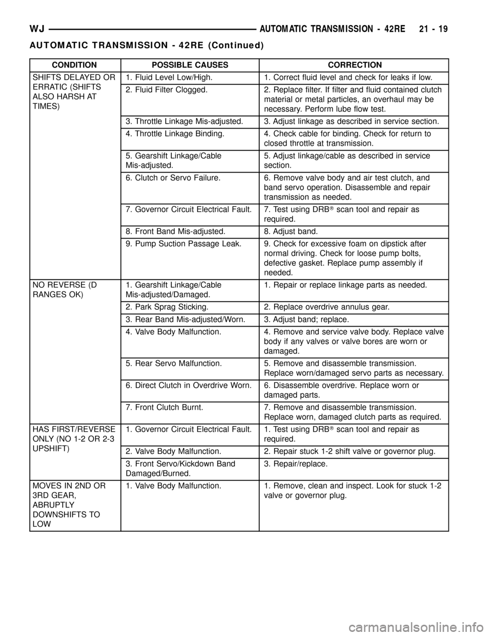
CONDITION POSSIBLE CAUSES CORRECTION
SHIFTS DELAYED OR
ERRATIC (SHIFTS
ALSO HARSH AT
TIMES)1. Fluid Level Low/High. 1. Correct fluid level and check for leaks if low.
2. Fluid Filter Clogged. 2. Replace filter. If filter and fluid contained clutch
material or metal particles, an overhaul may be
necessary. Perform lube flow test.
3. Throttle Linkage Mis-adjusted. 3. Adjust linkage as described in service section.
4. Throttle Linkage Binding. 4. Check cable for binding. Check for return to
closed throttle at transmission.
5. Gearshift Linkage/Cable
Mis-adjusted.5. Adjust linkage/cable as described in service
section.
6. Clutch or Servo Failure. 6. Remove valve body and air test clutch, and
band servo operation. Disassemble and repair
transmission as needed.
7. Governor Circuit Electrical Fault. 7. Test using DRBTscan tool and repair as
required.
8. Front Band Mis-adjusted. 8. Adjust band.
9. Pump Suction Passage Leak. 9. Check for excessive foam on dipstick after
normal driving. Check for loose pump bolts,
defective gasket. Replace pump assembly if
needed.
NO REVERSE (D
RANGES OK)1. Gearshift Linkage/Cable
Mis-adjusted/Damaged.1. Repair or replace linkage parts as needed.
2. Park Sprag Sticking. 2. Replace overdrive annulus gear.
3. Rear Band Mis-adjusted/Worn. 3. Adjust band; replace.
4. Valve Body Malfunction. 4. Remove and service valve body. Replace valve
body if any valves or valve bores are worn or
damaged.
5. Rear Servo Malfunction. 5. Remove and disassemble transmission.
Replace worn/damaged servo parts as necessary.
6. Direct Clutch in Overdrive Worn. 6. Disassemble overdrive. Replace worn or
damaged parts.
7. Front Clutch Burnt. 7. Remove and disassemble transmission.
Replace worn, damaged clutch parts as required.
HAS FIRST/REVERSE
ONLY (NO 1-2 OR 2-3
UPSHIFT)1. Governor Circuit Electrical Fault. 1. Test using DRBTscan tool and repair as
required.
2. Valve Body Malfunction. 2. Repair stuck 1-2 shift valve or governor plug.
3. Front Servo/Kickdown Band
Damaged/Burned.3. Repair/replace.
MOVES IN 2ND OR
3RD GEAR,
ABRUPTLY
DOWNSHIFTS TO
LOW1. Valve Body Malfunction. 1. Remove, clean and inspect. Look for stuck 1-2
valve or governor plug.
WJAUTOMATIC TRANSMISSION - 42RE 21 - 19
AUTOMATIC TRANSMISSION - 42RE (Continued)