2002 JEEP GRAND CHEROKEE Power train
[x] Cancel search: Power trainPage 1184 of 2199
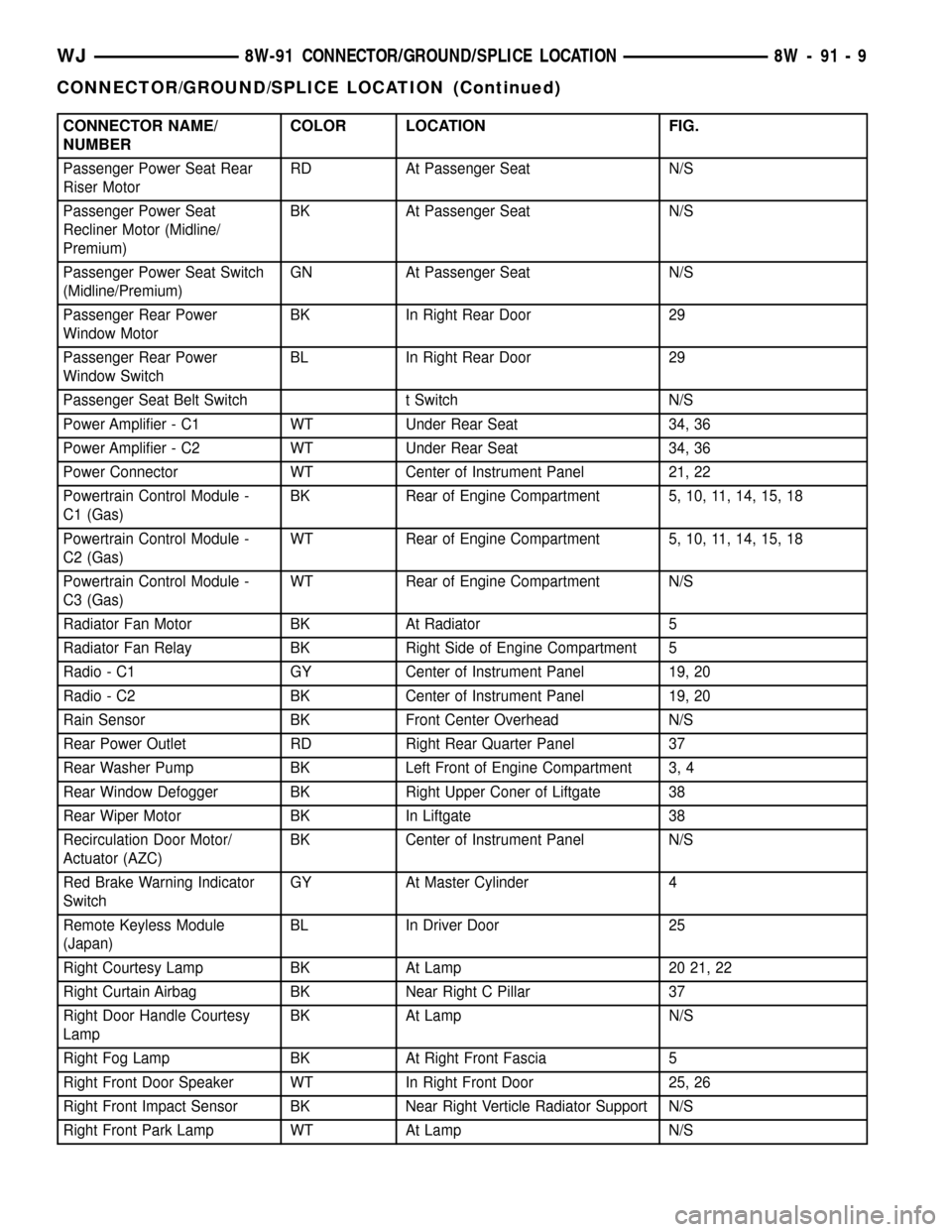
CONNECTOR NAME/
NUMBERCOLOR LOCATION FIG.
Passenger Power Seat Rear
Riser MotorRD At Passenger Seat N/S
Passenger Power Seat
Recliner Motor (Midline/
Premium)BK At Passenger Seat N/S
Passenger Power Seat Switch
(Midline/Premium)GN At Passenger Seat N/S
Passenger Rear Power
Window MotorBK In Right Rear Door 29
Passenger Rear Power
Window SwitchBL In Right Rear Door 29
Passenger Seat Belt Switch t Switch N/S
Power Amplifier - C1 WT Under Rear Seat 34, 36
Power Amplifier - C2 WT Under Rear Seat 34, 36
Power Connector WT Center of Instrument Panel 21, 22
Powertrain Control Module -
C1 (Gas)BK Rear of Engine Compartment 5, 10, 11, 14, 15, 18
Powertrain Control Module -
C2 (Gas)WT Rear of Engine Compartment 5, 10, 11, 14, 15, 18
Powertrain Control Module -
C3 (Gas)WT Rear of Engine Compartment N/S
Radiator Fan Motor BK At Radiator 5
Radiator Fan Relay BK Right Side of Engine Compartment 5
Radio - C1 GY Center of Instrument Panel 19, 20
Radio - C2 BK Center of Instrument Panel 19, 20
Rain Sensor BK Front Center Overhead N/S
Rear Power Outlet RD Right Rear Quarter Panel 37
Rear Washer Pump BK Left Front of Engine Compartment 3, 4
Rear Window Defogger BK Right Upper Coner of Liftgate 38
Rear Wiper Motor BK In Liftgate 38
Recirculation Door Motor/
Actuator (AZC)BK Center of Instrument Panel N/S
Red Brake Warning Indicator
SwitchGY At Master Cylinder 4
Remote Keyless Module
(Japan)BL In Driver Door 25
Right Courtesy Lamp BK At Lamp 20 21, 22
Right Curtain Airbag BK Near Right C Pillar 37
Right Door Handle Courtesy
LampBK At Lamp N/S
Right Fog Lamp BK At Right Front Fascia 5
Right Front Door Speaker WT In Right Front Door 25, 26
Right Front Impact Sensor BK Near Right Verticle Radiator Support N/S
Right Front Park Lamp WT At Lamp N/S
WJ8W-91 CONNECTOR/GROUND/SPLICE LOCATION 8W - 91 - 9
CONNECTOR/GROUND/SPLICE LOCATION (Continued)
Page 1187 of 2199
SPLICES
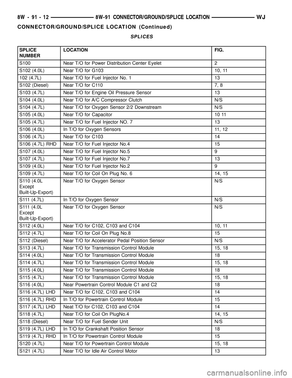
SPLICE
NUMBERLOCATION FIG.
S100 Near T/O for Power Distribution Center Eyelet 2
S102 (4.0L) Near T/O for G103 10, 11
102 (4.7L) Near T/O for Fuel Injector No. 1 13
S102 (Diesel) Near T/O for C110 7, 8
S103 (4.7L) Near T/O for Engine Oil Pressure Sensor 13
S104 (4.0L) Near T/O for A/C Compressor Clutch N/S
S104 (4.7L) Near T/O for Oxygen Sensor 2/2 Downstream N/S
S105 (4.0L) Near T/O for Capacitor 10 11
S105 (4.7L) Near T/O for Fuel Injector NO. 7 13
S106 (4.0L) In T/O for Oxygen Sensors 11, 12
S106 (4.7L) Near T/O for C103 14
S106 (4.7L) RHD Near T/O for Fuel Injector No.4 15
S107 (4.0L) Near T/O for Fuel Injector No.5 9
S107 (4.7L) Near T/O for Fuel Injector No.7 13
S109 (4.0L) Near T/O for Fuel Injector No.2 9
S109 (4.7L) Near T/O for Coil On Plug No. 6 14, 15
S110 (4.0L
Except
Built-Up-Export)Near T/O for Oxygen Sensor N/S
S111 (4.7L) In T/O for Oxygen Sensor N/S
S111 (4.0L
Except
Built-Up-Export)Near T/O for Oxygen Sensor N/S
S112 (4.0L) Near T/O for C102, C103 and C104 10, 11
S112 (4.7L) Near T/O for Coil On Plug No.8 15
S112 (Diesel) Near T/O for Accelerator Pedal Position Sensor N/S
S113 (4.7L) Near T/O for Transmission Control Module 15, 18
S114 (4.0L) Near T/O for Transmission Control Module 18
S114 (4.7L) Near T/O for Transmission Control Module 15, 18
S115 (4.0L) Near T/O for Transmission Control Module 18
S115 (4.7L) Near T/O for Transmission Control Module 15, 18
S116 (4.0L) Near Powertrain Control Module C1 and C2 18
S116 (4.7L) LHD Near T/O for C102, C103 and C104 14
S116 (4.7L) RHD In T/O for Powertrain Control Module 15
S117 (4.7L) LHD Neat T/O for C102, C103 and C104 14
S118 (4.7L) Near T/O for Coil On PlugNo.4 14, 15
S118 (Diesel) Near T/O for Fuel Sender Unit N/S
S119 (4.7L) LHD In T/O for Crankshaft Position Sensor 18
S119 (4.7L) RHD In T/O for Powertrain Control Module 15
S120 (4.7L) Near T/O for Powertrain Control Module 15, 18
S121 (4.7L) Near T/O for Idle Air Control Motor 13
8W - 91 - 12 8W-91 CONNECTOR/GROUND/SPLICE LOCATIONWJ
CONNECTOR/GROUND/SPLICE LOCATION (Continued)
Page 1188 of 2199
SPLICE
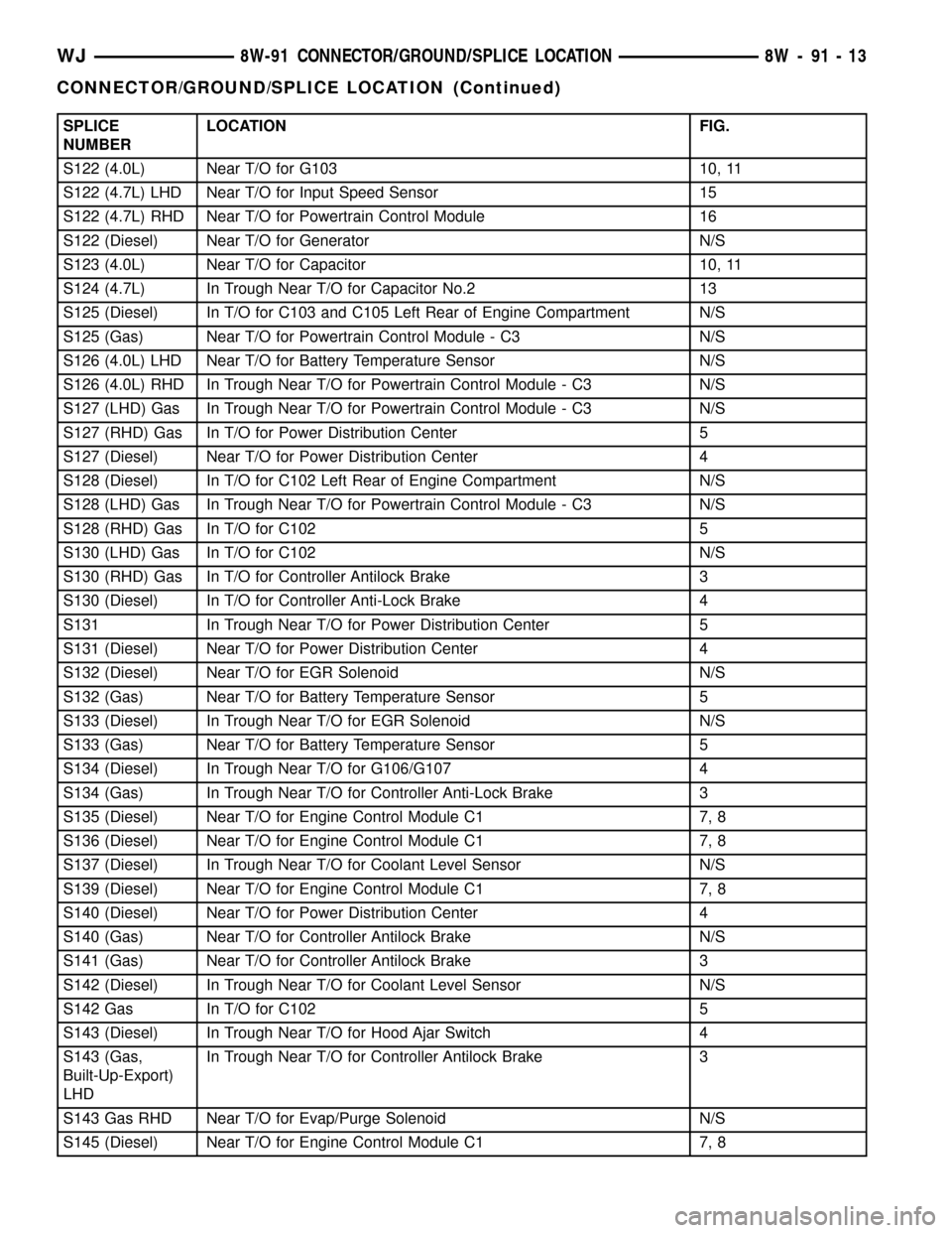
NUMBERLOCATION FIG.
S122 (4.0L) Near T/O for G103 10, 11
S122 (4.7L) LHD Near T/O for Input Speed Sensor 15
S122 (4.7L) RHD Near T/O for Powertrain Control Module 16
S122 (Diesel) Near T/O for Generator N/S
S123 (4.0L) Near T/O for Capacitor 10, 11
S124 (4.7L) In Trough Near T/O for Capacitor No.2 13
S125 (Diesel) In T/O for C103 and C105 Left Rear of Engine Compartment N/S
S125 (Gas) Near T/O for Powertrain Control Module - C3 N/S
S126 (4.0L) LHD Near T/O for Battery Temperature Sensor N/S
S126 (4.0L) RHD In Trough Near T/O for Powertrain Control Module - C3 N/S
S127 (LHD) Gas In Trough Near T/O for Powertrain Control Module - C3 N/S
S127 (RHD) Gas In T/O for Power Distribution Center 5
S127 (Diesel) Near T/O for Power Distribution Center 4
S128 (Diesel) In T/O for C102 Left Rear of Engine Compartment N/S
S128 (LHD) Gas In Trough Near T/O for Powertrain Control Module - C3 N/S
S128 (RHD) Gas In T/O for C102 5
S130 (LHD) Gas In T/O for C102 N/S
S130 (RHD) Gas In T/O for Controller Antilock Brake 3
S130 (Diesel) In T/O for Controller Anti-Lock Brake 4
S131 In Trough Near T/O for Power Distribution Center 5
S131 (Diesel) Near T/O for Power Distribution Center 4
S132 (Diesel) Near T/O for EGR Solenoid N/S
S132 (Gas) Near T/O for Battery Temperature Sensor 5
S133 (Diesel) In Trough Near T/O for EGR Solenoid N/S
S133 (Gas) Near T/O for Battery Temperature Sensor 5
S134 (Diesel) In Trough Near T/O for G106/G107 4
S134 (Gas) In Trough Near T/O for Controller Anti-Lock Brake 3
S135 (Diesel) Near T/O for Engine Control Module C1 7, 8
S136 (Diesel) Near T/O for Engine Control Module C1 7, 8
S137 (Diesel) In Trough Near T/O for Coolant Level Sensor N/S
S139 (Diesel) Near T/O for Engine Control Module C1 7, 8
S140 (Diesel) Near T/O for Power Distribution Center 4
S140 (Gas) Near T/O for Controller Antilock Brake N/S
S141 (Gas) Near T/O for Controller Antilock Brake 3
S142 (Diesel) In Trough Near T/O for Coolant Level Sensor N/S
S142 Gas In T/O for C102 5
S143 (Diesel) In Trough Near T/O for Hood Ajar Switch 4
S143 (Gas,
Built-Up-Export)
LHDIn Trough Near T/O for Controller Antilock Brake 3
S143 Gas RHD Near T/O for Evap/Purge Solenoid N/S
S145 (Diesel) Near T/O for Engine Control Module C1 7, 8
WJ8W-91 CONNECTOR/GROUND/SPLICE LOCATION 8W - 91 - 13
CONNECTOR/GROUND/SPLICE LOCATION (Continued)
Page 1226 of 2199

8W-97 POWER DISTRIBUTION
TABLE OF CONTENTS
page page
POWER DISTRIBUTION
DESCRIPTION..........................1
OPERATION............................1
SPECIAL TOOLS
POWER DISTRIBUTION SYSTEMS.........2
CIGAR LIGHTER OUTLET
DESCRIPTION..........................2
OPERATION............................2
DIAGNOSIS AND TESTING - CIGAR LIGHTER
OUTLET.............................2
CIGAR LIGHTER OUTLET DOOR SPRING
REMOVAL.............................3
INSTALLATION..........................3
IOD FUSE
DESCRIPTION..........................3
OPERATION............................4
REMOVAL.............................4
INSTALLATION..........................4
JUNCTION BLOCK
DESCRIPTION..........................5
OPERATION............................5
REMOVAL.............................5
INSTALLATION..........................6
POWER DISTRIBUTION CENTER
DESCRIPTION..........................7
OPERATION............................8
REMOVAL.............................8
DISASSEMBLY
POWER DISTRIBUTION CENTER
DISASSEMBLY........................9ASSEMBLY
POWER DISTRIBUTION CENTER
ASSEMBLY..........................11
INSTALLATION.........................12
POWER OUTLET
DESCRIPTION - FRONT POWER OUTLET....12
OPERATION - FRONT POWER OUTLET......12
DIAGNOSIS AND TESTING - POWER OUTLET . 12
REMOVAL.............................13
INSTALLATION.........................13
POWER OUTLET RELAY
DESCRIPTION.........................13
OPERATION...........................14
DIAGNOSIS AND TESTING - POWER OUTLET
RELAY..............................14
REMOVAL.............................15
INSTALLATION.........................15
IOD WIRE HARNESS CONNECTOR
DESCRIPTION.........................15
OPERATION...........................15
FUSE COVER
REMOVAL.............................16
INSTALLATION.........................16
REAR POWER OUTLET
DESCRIPTION - REAR POWER OUTLET.....16
OPERATION - REAR POWER OUTLET.......17
DIAGNOSIS AND TESTING - REAR POWER
OUTLET............................17
REMOVAL.............................17
INSTALLATION.........................18
POWER DISTRIBUTION
DESCRIPTION
This group covers the various standard and
optional power distribution components used on this
model. The power distribution system for this vehicle
consists of the following components:
²Power Distribution Center (PDC)
²Junction Block (JB)
²Power Outlets
The power distribution system also incorporates
various types of circuit control and protection fea-
tures, including:
²Automatic resetting circuit breakers
²Blade-type fuses
²Bus bars
²Cartridge fuses²Circuit splice blocks
²Flashers
²Fusible links
²Standard and Micro-Relays
Following are general descriptions of the major
components in the power distribution system. See the
owner's manual in the vehicle glove box for more
information on the features and use of all of the
power distribution system components. Refer to Wir-
ing Diagrams for complete circuit diagrams.
OPERATION
The power distribution system for this vehicle is
designed to provide safe, reliable, and centralized dis-
tribution points for the electrical current required to
operate all of the standard and optional factory-in-
stalled electrical and electronic powertrain, chassis,
safety, security, comfort and convenience systems. At
WJ8W-97 POWER DISTRIBUTION 8W - 97 - 1
Page 1237 of 2199

PDC LOWER COVER INSTALLATION
(1) Align the PDC housing lower cover on the bot-
tom of the PDC.
(2) Evenly press the lower cover into place until
latches are fully engaged.
(3) Where the right headlamp and dash harness
enters the PDC, tape the harness securely to the
trough formation on the PDC lower cover.
(4) Install the PDC in its mounting location on the
battery support.
(5) Install the battery wire harness over the two
PDC B+ terminal studs. Torque the nuts to 11.3 N´m
(100 in. lbs.).
(6) Install the battery. Refer to Battery System for
the procedure.
(7) Install the PDC cover.
INSTALLATION
The Power Distribution Center (PDC) main hous-
ing unit, the PDC fuse wedges and the PDC bus bars
cannot be repaired and are only serviced as a unit
with the right headlamp and dash wire harness. If
the PDC main housing unit, the fuse wedges or the
bus bars are faulty or damaged, the entire PDC and
right headlamp and dash wire harness unit must be
replaced.
(1) Position the PDC and the right headlamp and
dash wire harness unit in the engine compartment.
(2) Engage the PDC housing mounts with the
stanchions of the battery support and push the unit
downward until the mount latches fully engage the
mounting tabs on the stanchions.
(3) Install the two-holed eyelet of the battery wire
harness PDC take outs onto the two PDC B(+) termi-
nal studs.
(4) Install and tighten the nuts that secure the
eyelet of the battery wire harness PDC take outs to
the B(+) terminal studs. Tighten the nuts to 11.3
N´m (100 in. lbs.).
(5) Engage each of the retainers that secure the
right headlamp and dash wire harness to the vehicle
body and chassis components. Refer toConnector
Locationsin Wiring Diagrams for the location of
more information on the right headlamp and dash
wire harness retainer locations.
(6) Install all of the fasteners that secure each of
the right headlamp and dash wire harness ground
eyelets to the vehicle body and chassis components.
Refer toConnector Locationsin Wiring Diagrams
for the location of more information on the ground
eyelet locations.
(7) Reconnect each of the right headlamp and dash
wire harness connectors. Refer toConnector Loca-
tionsin Wiring Diagrams for the location of more
information on the right headlamp and dash wire
harness connector locations. For connectors securedwith screws, tighten the screws to 4.3 N´m (38 in.
lbs.).
(8) Reconnect the battery negative cable.
POWER OUTLET
DESCRIPTION - FRONT POWER OUTLET
An accessory power outlet is standard equipment
on this model. The power outlet is installed in the
instrument panel center lower bezel, which is located
near the bottom of the instrument panel center stack
area, below the heater and air conditioner controls.
The power outlet base is secured by a snap fit within
the center lower bezel. A hinged door with an over-
center spring flips closed to conceal and protect the
power outlet base when the power outlet is not being
used, and flips open below the center lower bezel
while the power outlet is in use.
The power outlet receptacle unit and the power
outlet door are each available for service replace-
ment.
OPERATION - FRONT POWER OUTLET
The power outlet base or receptacle shell is con-
nected to ground, and an insulated contact in the
bottom of the shell is connected to battery current.
The power outlet receives battery voltage from a fuse
in the junction block at all times.
While the power outlet is very similar to a cigar
lighter base unit, it does not include the two small
spring-clip retainers inside the bottom of the recepta-
cle shell that are used to secure the cigar lighter
heating element to the insulated contact.
DIAGNOSIS AND TESTING - POWER OUTLET
For complete circuit diagrams, refer toHorn/Ci-
gar Lighter/Power Outletin Wiring Diagrams.
WARNING: REFER TO RESTRAINTS BEFORE
ATTEMPTING ANY STEERING WHEEL, STEERING
COLUMN, OR INSTRUMENT PANEL COMPONENT
DIAGNOSIS OR SERVICE. FAILURE TO TAKE THE
PROPER PRECAUTIONS COULD RESULT IN ACCI-
DENTAL AIRBAG DEPLOYMENT AND POSSIBLE
PERSONAL INJURY.
(1) Check the fused B(+) fuse in the junction block.
If OK, go to Step 2. If not OK, repair the shorted cir-
cuit or component as required and replace the faulty
fuse.
(2) Check for battery voltage at the fused B(+) fuse
in the junction block. If OK, go to Step 3. If not OK,
repair the open fused B(+) circuit to the Power Dis-
tribution Center (PDC) fuse as required.
(3) Open the power outlet door. Check for continu-
ity between the inside circumference of the power
8W - 97 - 12 8W-97 POWER DISTRIBUTIONWJ
POWER DISTRIBUTION CENTER (Continued)
Page 1239 of 2199
The cigar lighter relay cannot be repaired or
adjusted and, if faulty or damaged, it must be
replaced.
OPERATION
The ISO relay consists of an electromagnetic coil, a
resistor or diode, and three (two fixed and one mov-
able) electrical contacts. The movable (common feed)
relay contact is held against one of the fixed contacts
(normally closed) by spring pressure. When the elec-
tromagnetic coil is energized, it draws the movable
contact away from the normally closed fixed contact,
and holds it against the other (normally open) fixed
contact.
When the electromagnetic coil is de-energized,
spring pressure returns the movable contact to the
normally closed position. The resistor or diode is con-
nected in parallel with the electromagnetic coil in the
relay, and helps to dissipate voltage spikes that are
produced when the coil is de-energized.
DIAGNOSIS AND TESTING - POWER OUTLET
RELAY
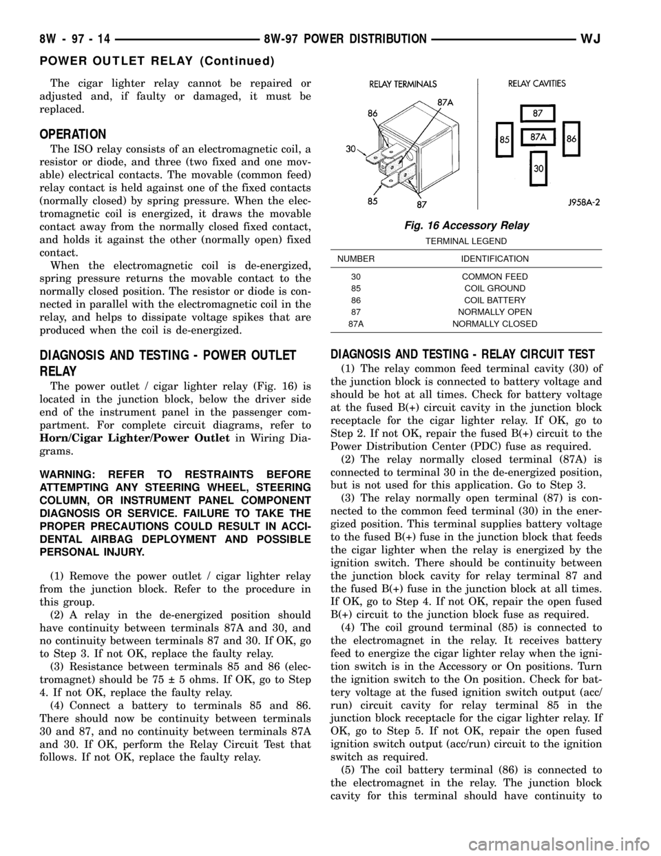
The power outlet / cigar lighter relay (Fig. 16) is
located in the junction block, below the driver side
end of the instrument panel in the passenger com-
partment. For complete circuit diagrams, refer to
Horn/Cigar Lighter/Power Outletin Wiring Dia-
grams.
WARNING: REFER TO RESTRAINTS BEFORE
ATTEMPTING ANY STEERING WHEEL, STEERING
COLUMN, OR INSTRUMENT PANEL COMPONENT
DIAGNOSIS OR SERVICE. FAILURE TO TAKE THE
PROPER PRECAUTIONS COULD RESULT IN ACCI-
DENTAL AIRBAG DEPLOYMENT AND POSSIBLE
PERSONAL INJURY.
(1) Remove the power outlet / cigar lighter relay
from the junction block. Refer to the procedure in
this group.
(2) A relay in the de-energized position should
have continuity between terminals 87A and 30, and
no continuity between terminals 87 and 30. If OK, go
to Step 3. If not OK, replace the faulty relay.
(3) Resistance between terminals 85 and 86 (elec-
tromagnet) should be 75 5 ohms. If OK, go to Step
4. If not OK, replace the faulty relay.
(4) Connect a battery to terminals 85 and 86.
There should now be continuity between terminals
30 and 87, and no continuity between terminals 87A
and 30. If OK, perform the Relay Circuit Test that
follows. If not OK, replace the faulty relay.
DIAGNOSIS AND TESTING - RELAY CIRCUIT TEST
(1) The relay common feed terminal cavity (30) of
the junction block is connected to battery voltage and
should be hot at all times. Check for battery voltage
at the fused B(+) circuit cavity in the junction block
receptacle for the cigar lighter relay. If OK, go to
Step 2. If not OK, repair the fused B(+) circuit to the
Power Distribution Center (PDC) fuse as required.
(2) The relay normally closed terminal (87A) is
connected to terminal 30 in the de-energized position,
but is not used for this application. Go to Step 3.
(3) The relay normally open terminal (87) is con-
nected to the common feed terminal (30) in the ener-
gized position. This terminal supplies battery voltage
to the fused B(+) fuse in the junction block that feeds
the cigar lighter when the relay is energized by the
ignition switch. There should be continuity between
the junction block cavity for relay terminal 87 and
the fused B(+) fuse in the junction block at all times.
If OK, go to Step 4. If not OK, repair the open fused
B(+) circuit to the junction block fuse as required.
(4) The coil ground terminal (85) is connected to
the electromagnet in the relay. It receives battery
feed to energize the cigar lighter relay when the igni-
tion switch is in the Accessory or On positions. Turn
the ignition switch to the On position. Check for bat-
tery voltage at the fused ignition switch output (acc/
run) circuit cavity for relay terminal 85 in the
junction block receptacle for the cigar lighter relay. If
OK, go to Step 5. If not OK, repair the open fused
ignition switch output (acc/run) circuit to the ignition
switch as required.
(5) The coil battery terminal (86) is connected to
the electromagnet in the relay. The junction block
cavity for this terminal should have continuity to
Fig. 16 Accessory Relay
TERMINAL LEGEND
NUMBER IDENTIFICATION
30 COMMON FEED
85 COIL GROUND
86 COIL BATTERY
87 NORMALLY OPEN
87A NORMALLY CLOSED
8W - 97 - 14 8W-97 POWER DISTRIBUTIONWJ
POWER OUTLET RELAY (Continued)
Page 1292 of 2199
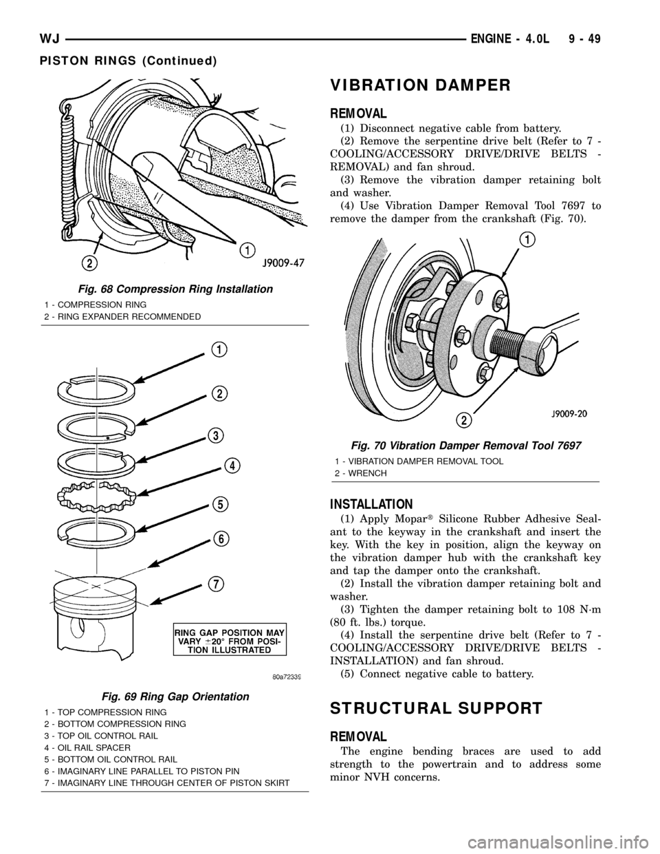
VIBRATION DAMPER
REMOVAL
(1) Disconnect negative cable from battery.
(2) Remove the serpentine drive belt (Refer to 7 -
COOLING/ACCESSORY DRIVE/DRIVE BELTS -
REMOVAL) and fan shroud.
(3) Remove the vibration damper retaining bolt
and washer.
(4) Use Vibration Damper Removal Tool 7697 to
remove the damper from the crankshaft (Fig. 70).
INSTALLATION
(1) Apply MopartSilicone Rubber Adhesive Seal-
ant to the keyway in the crankshaft and insert the
key. With the key in position, align the keyway on
the vibration damper hub with the crankshaft key
and tap the damper onto the crankshaft.
(2) Install the vibration damper retaining bolt and
washer.
(3) Tighten the damper retaining bolt to 108 N´m
(80 ft. lbs.) torque.
(4) Install the serpentine drive belt (Refer to 7 -
COOLING/ACCESSORY DRIVE/DRIVE BELTS -
INSTALLATION) and fan shroud.
(5) Connect negative cable to battery.
STRUCTURAL SUPPORT
REMOVAL
The engine bending braces are used to add
strength to the powertrain and to address some
minor NVH concerns.
Fig. 68 Compression Ring Installation
1 - COMPRESSION RING
2 - RING EXPANDER RECOMMENDED
Fig. 69 Ring Gap Orientation
1 - TOP COMPRESSION RING
2 - BOTTOM COMPRESSION RING
3 - TOP OIL CONTROL RAIL
4 - OIL RAIL SPACER
5 - BOTTOM OIL CONTROL RAIL
6 - IMAGINARY LINE PARALLEL TO PISTON PIN
7 - IMAGINARY LINE THROUGH CENTER OF PISTON SKIRT
Fig. 70 Vibration Damper Removal Tool 7697
1 - VIBRATION DAMPER REMOVAL TOOL
2 - WRENCH
WJENGINE - 4.0L 9 - 49
PISTON RINGS (Continued)
Page 1299 of 2199

(9) Lower the engine until it is properly located on
the engine mounts.
(10) Install the through bolts and tighten the nuts.
(11) Lower the jack stand and remove the piece of
wood.
(12) Install the engine flywheel and transmission
torque converter housing access cover.
(13) Install the engine starter motor. (Refer to 8 -
ELECTRICAL/STARTING/STARTER MOTOR -
INSTALLATION).
(14) Connect the exhaust pipe to the hanger and to
the engine exhaust manifold.
(15) Install transmission oil cooling lines (if
equipped) and oxygen sensor wiring supports that
attach to the oil pan studs.
(16) Install the oil pan drain plug (Fig. 81).
Tighten the plug to 34 N´m (25 ft. lbs.) torque.
(17) Lower the vehicle.
(18) Connect negative cable to battery.
(19) Fill the oil pan with engine oil to the specified
level.
WARNING: USE EXTREME CAUTION WHEN THE
ENGINE IS OPERATING. DO NOT STAND IN A
DIRECT LINE WITH THE FAN. DO NOT PUT YOUR
HANDS NEAR THE PULLEYS, BELTS OR FAN. DO
NOT WEAR LOOSE CLOTHING.
(20) Start the engine and inspect for leaks.
ENGINE OIL PRESSURE
SENSOR
DESCRIPTION
The 3±wire, solid-state engine oil pressure sensor
(sending unit) is located in an engine oil pressure
gallery.
OPERATION
The oil pressure sensor uses three circuits. They
are:
²A 5±volt power supply from the Powertrain Con-
trol Module (PCM)
²A sensor ground through the PCM's sensor
return
²A signal to the PCM relating to engine oil pres-
sure
The oil pressure sensor has a 3±wire electrical
function very much like the Manifold Absolute Pres-
sure (MAP) sensor. Meaning different pressures
relate to different output voltages.
A 5±volt supply is sent to the sensor from the PCM
to power up the sensor. The sensor returns a voltage
signal back to the PCM relating to engine oil pres-
sure. This signal is then transferred (bussed) to theinstrument panel on either a CCD or PCI bus circuit
(depending on vehicle line) to operate the oil pressure
gauge and the check gauges lamp. Ground for the
sensor is provided by the PCM through a low-noise
sensor return.
OIL PUMP
REMOVAL
A gear-type oil pump is mounted at the underside
of the cylinder block opposite the No.4 main bearing.
(1) Drain the engine oil.
(2) Remove the oil pan (Refer to 9 - ENGINE/LU-
BRICATION/OIL PAN - REMOVAL).
(3) Remove the pump-to-cylinder block attaching
bolts. Remove the pump assembly with gasket (Fig.
82).
CAUTION: If the oil pump is not to be serviced, DO
NOT disturb position of oil inlet tube and strainer
assembly in pump body. If the tube is moved within
the pump body, a replacement tube and strainer
assembly must be installed to assure an airtight
seal.
Fig. 82 Oil Pump Assembly
1 - OIL FILTER ADAPTOR
2 - BLOCK
3 - GASKET
4 - OIL INLET TUBE
5 - OIL PUMP
6 - STRAINER ASSEMBLY
7 - ATTACHING BOLTS
9 - 56 ENGINE - 4.0LWJ
OIL PAN (Continued)