2002 JEEP GRAND CHEROKEE Gear
[x] Cancel search: GearPage 169 of 2199

CAUTION: Vari-lokTplenum must be seated against
the differential case prior to installing the ring gear
side differential bearing.
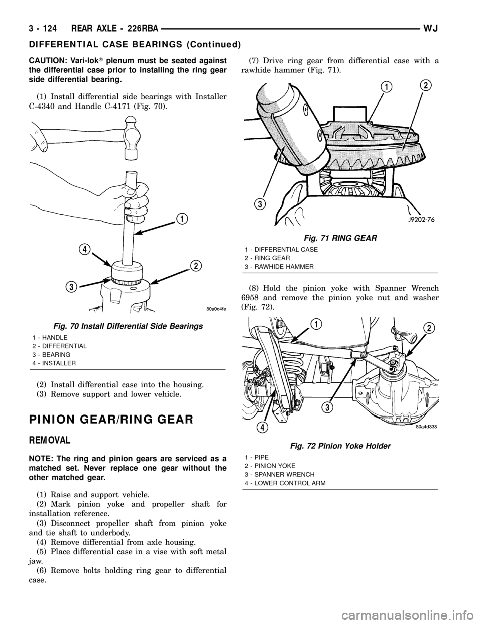
(1) Install differential side bearings with Installer
C-4340 and Handle C-4171 (Fig. 70).
(2) Install differential case into the housing.
(3) Remove support and lower vehicle.
PINION GEAR/RING GEAR
REMOVAL
NOTE: The ring and pinion gears are serviced as a
matched set. Never replace one gear without the
other matched gear.
(1) Raise and support vehicle.
(2) Mark pinion yoke and propeller shaft for
installation reference.
(3) Disconnect propeller shaft from pinion yoke
and tie shaft to underbody.
(4) Remove differential from axle housing.
(5) Place differential case in a vise with soft metal
jaw.
(6) Remove bolts holding ring gear to differential
case.(7) Drive ring gear from differential case with a
rawhide hammer (Fig. 71).
(8) Hold the pinion yoke with Spanner Wrench
6958 and remove the pinion yoke nut and washer
(Fig. 72).
Fig. 70 Install Differential Side Bearings
1 - HANDLE
2 - DIFFERENTIAL
3 - BEARING
4 - INSTALLER
Fig. 71 RING GEAR
1 - DIFFERENTIAL CASE
2 - RING GEAR
3 - RAWHIDE HAMMER
Fig. 72 Pinion Yoke Holder
1 - PIPE
2 - PINION YOKE
3 - SPANNER WRENCH
4 - LOWER CONTROL ARM
3 - 124 REAR AXLE - 226RBAWJ
DIFFERENTIAL CASE BEARINGS (Continued)
Page 170 of 2199

(9) Remove pinion yoke from pinion shaft with
Remover C-452 and Wrench C-3281 (Fig. 73).
(10) Remove pinion gear from housing (Fig. 74).(11) Remove pinion seal with Remover 7794-A and
a slide hammer (Fig. 75).
(12) Remove oil slinger, if equipped, and front pin-
ion bearing.
(13) Remove the front pinion bearing cup with
Remover D-103 and Handle C-4171 (Fig. 76).
Fig. 73 Pinion Yoke Remover
1 - FLANGE WRENCH
2 - YOKE
3 - YOKE PULLER
Fig. 74 Pinion Gear
1 - RAWHIDE HAMMER
Fig. 75 Pinion Seal Remover
1 - REMOVER
2 - SLIDE HAMMER
3 - PINION SEAL
Fig. 76 Front Pinion Bearing Cup
1 - REMOVER
2 - HANDLE
WJREAR AXLE - 226RBA 3 - 125
PINION GEAR/RING GEAR (Continued)
Page 171 of 2199

(14) Remove rear bearing cup from housing (Fig.
77) with Remover C-4307 and Handle C-4171.
(15) Remove collapsible preload spacer (Fig. 78).
(16) Remove rear bearing from the pinion with
Puller/Press C-293-PA and Adapters C-293-42 (Fig.
79).
(17) Remove depth shims from the pinion gear
shaft and record shim thickness.
INSTALLATION
NOTE: A pinion depth shim/oil slinger is placed
between the rear pinion bearing cone and the pin-
ion head to achieve proper ring gear and pinion
mesh. If ring gear and pinion are reused, the pinion
depth shim/oil slinger should not require replace-
ment. Refer to Adjustment (Pinion Gear Depth) to
select the proper thickness shim/oil slinger if ring
and pinion gears are replaced.
Fig. 77 Rear Pinion Bearing Cup
1 - REMOVER
2 - HANDLE
Fig. 78 Collapsible Spacer
1 - COLLAPSIBLE SPACER
2 - SHOULDER
3 - PINION GEAR
4 - DEPTH SHIM
5 - REAR BEARING
Fig. 79 Rear Pinion Bearing Puller
1 - PULLER
2 - VISE
3 - ADAPTERS
4 - PINION GEAR SHAFT
3 - 126 REAR AXLE - 226RBAWJ
PINION GEAR/RING GEAR (Continued)
Page 172 of 2199

(1) Apply Mopar Door Ease or equivalent lubricant
to outside surface of pinion bearing cups.
(2) Install pinion rear bearing cup with Installer
C-4308 and Driver Handle C-4171 (Fig. 80) and ver-
ify cup is seated.
(3) Install pinion front bearing cup with Installer
D-129 and Handle C-4171 (Fig. 81) and verify cup is
seated.(4) Install pinion front bearing and oil slinger, if
equipped.
(5) Apply a light coating of gear lubricant on the
lip of pinion seal. Install seal with an appropriate
(Fig. 82).
(6) Install depth shim on the pinion gear.
(7) Install rear bearing on the pinion gear with
Installer 6448 and a press (Fig. 83).
Fig. 80 Rear Pinion Bearing Cup
1 - INSTALLER
2 - HANDLE
Fig. 81 FRONT PINION BEARING CUP
1 - INSTALLER
2 - HANDLE
Fig. 82 PINION SEAL INSTALLER
1 - HANDLE
2 - INSTALLER
Fig. 83 REAR PINION BEARING
1 - PRESS
2 - INSTALLER
3 - PINION GEAR
4 - PINION BEARING
WJREAR AXLE - 226RBA 3 - 127
PINION GEAR/RING GEAR (Continued)
Page 173 of 2199

(8) Install anewcollapsible preload spacer on pin-
ion shaft and install pinion gear in the housing (Fig.
84).
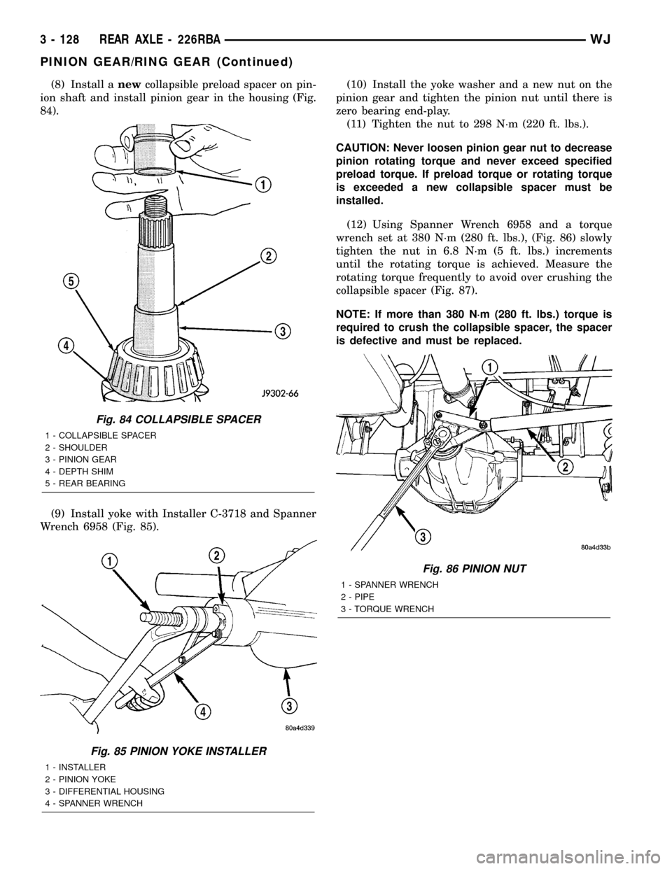
(9) Install yoke with Installer C-3718 and Spanner
Wrench 6958 (Fig. 85).(10) Install the yoke washer and a new nut on the
pinion gear and tighten the pinion nut until there is
zero bearing end-play.
(11) Tighten the nut to 298 N´m (220 ft. lbs.).
CAUTION: Never loosen pinion gear nut to decrease
pinion rotating torque and never exceed specified
preload torque. If preload torque or rotating torque
is exceeded a new collapsible spacer must be
installed.
(12) Using Spanner Wrench 6958 and a torque
wrench set at 380 N´m (280 ft. lbs.), (Fig. 86) slowly
tighten the nut in 6.8 N´m (5 ft. lbs.) increments
until the rotating torque is achieved. Measure the
rotating torque frequently to avoid over crushing the
collapsible spacer (Fig. 87).
NOTE: If more than 380 N´m (280 ft. lbs.) torque is
required to crush the collapsible spacer, the spacer
is defective and must be replaced.
Fig. 84 COLLAPSIBLE SPACER
1 - COLLAPSIBLE SPACER
2 - SHOULDER
3 - PINION GEAR
4 - DEPTH SHIM
5 - REAR BEARING
Fig. 85 PINION YOKE INSTALLER
1 - INSTALLER
2 - PINION YOKE
3 - DIFFERENTIAL HOUSING
4 - SPANNER WRENCH
Fig. 86 PINION NUT
1 - SPANNER WRENCH
2 - PIPE
3 - TORQUE WRENCH
3 - 128 REAR AXLE - 226RBAWJ
PINION GEAR/RING GEAR (Continued)
Page 174 of 2199

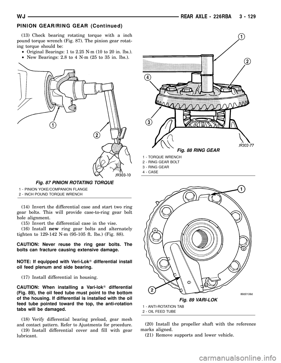
(13) Check bearing rotating torque with a inch
pound torque wrench (Fig. 87). The pinion gear rotat-
ing torque should be:
²
Original Bearings: 1 to 2.25 N´m (10 to 20 in. lbs.).
²New Bearings: 2.8 to 4 N´m (25 to 35 in. lbs.).
(14) Invert the differential case and start two ring
gear bolts. This will provide case-to-ring gear bolt
hole alignment.
(15) Invert the differential case in the vise.
(16) Installnewring gear bolts and alternately
tighten to 129-142 N´m (95-105 ft. lbs.) (Fig. 88).
CAUTION: Never reuse the ring gear bolts. The
bolts can fracture causing extensive damage.
NOTE: If equipped with Veri-LokTdifferential install
oil feed plenum and side bearing.
(17) Install differential in housing.
CAUTION: When installing a Vari-lokTdifferential
(Fig. 89), the oil feed tube must point to the bottom
of the housing. If differential is installed with the oil
feed tube pointed toward the top, the anti-rotation
tabs will be damaged.
(18)
Verify differential bearing preload, gear mesh
and contact pattern. Refer to Ajustments for procedure.
(19) Install differential cover and fill with gear
lubricant.(20) Install the propeller shaft with the reference
marks aligned.
(21) Remove supports and lower vehicle.
Fig. 87 PINION ROTATING TORQUE
1 - PINION YOKE/COMPANION FLANGE
2 - INCH POUND TORQUE WRENCH
Fig. 88 RING GEAR
1 - TORQUE WRENCH
2 - RING GEAR BOLT
3 - RING GEAR
4 - CASE
Fig. 89 VARI-LOK
1 - ANTI-ROTATION TAB
2 - OIL FEED TUBE
WJREAR AXLE - 226RBA 3 - 129
PINION GEAR/RING GEAR (Continued)
Page 218 of 2199

ELECTRIC BRAKE
DESCRIPTION
The electronic brake distribution (EBD) functions
like a rear proportioning valve. The EBD system uses
the ABS system to control the slip of the rear wheels
in partial braking range. The braking force of the
rear wheels is controlled electronically by using the
inlet and outlet valves located in the HCU.
OPERATION
Upon entry into EBD the inlet valve for the rear
brake circuit is switched on so that the fluid supply
from the master cylinder is shut off. In order to
decrease the rear brake pressure the outlet valve for
the rear brake circuit is pulsed. This allows fluid to
enter the low pressure accumulator (LPA) in the
HCU resulting in a drop in fluid pressure to the rear
brakes. In order to increase the rear brake pressure
the outlet valve is switched off and the inlet valve is
pulsed. This increases the pressure to the rear
brakes. This will continue until the required slip dif-
ference is obtained. At the end of EBD braking (no
brake application) the fluid in the LPA drains back to
the master cylinder by switching on the outlet valve
and draining through the inlet valve check valve. At
the same time the inlet valve is switched on to pre-
vent a hydraulic short circiut in case of another
brake application.
The EBD will remain functional during many ABS
fault modes. If the red and amber warning lamps are
illuminated the EBD may have a fault.
FRONT WHEEL SPEED
SENSOR
DESCRIPTION
A wheel speed sensor is used at each wheel. The
front sensors are mounted to the steering knuckles.
The rear sensors are mounted at the outboard end of
the axle. Tone wheels are mounted to the outboard
ends of the front and rear axle shafts. The gear type
tone wheel serves as the trigger mechanism for each
sensor.
OPERATION
The sensors convert wheel speed into a small digi-
tal signal. The CAB sends 12 volts to the sensors.
The sensor has an internal magneto resistance
bridge that alters the voltage and amperage of the
signal circuit. This voltage and amperage is changed
by magnetic induction when the toothed tone wheel
passes the wheel speed sensor. This digital signal issent to the CAB. The CAB measures the voltage and
amperage of the digital signal for each wheel.
REMOVAL
(1) Raise and support the vehicle.
(2) Remove the front wheel sensor mounting bolt
(Fig. 1).
(3) Remove the sensor from the steering knuckle.
(4) Disengage the sensor wire from the brackets
(Fig. 1)on the steering knuckle.
(5) Disconnect the sensor from the sensor harness
(Fig. 2)and (Fig. 3).
(6) Remove the sensor and wire.
INSTALLATION
(1) Install the sensor on the steering knuckle.
(2) Apply Mopar Lock N' Seal or Loctitet242 to
the sensor mounting bolt. Use new sensor bolt if orig-
inal bolt is worn or damaged.
(3) Install the sensor mounting bolt and tighten
bolt to 12-14 N´m (106-124 in. lbs.).
(4) Engage the grommets on the sensor wire to the
steering knuckle brackets.
(5) Connect the sensor wire to the harness connec-
tor.
(6) Check the sensor wire routing. Be sure the
wire is clear of all chassis components and is not
twisted or kinked at any spot.
(7) Remove the support and lower vehicle.
Fig. 1 Sensor Location
1 - BRACKET
2 - BRACKET
3 - WHEEL SPEED SENSOR
4 - MOUNTING BOLT
WJBRAKES - ABS 5 - 43
Page 220 of 2199

(3) Connect the harness to the switch. Be sure the
harness connector is firmly seated.
(4) Place the carpet in position and fold the rear
seat back down.
REAR WHEEL SPEED SENSOR
DESCRIPTION
A wheel speed sensor is used at each wheel. The
front sensors are mounted to the steering knuckles.The rear sensors are mounted at the outboard end of
the axle. Tone wheels are mounted to the outboard
ends of the front and rear axle shafts. The gear type
tone wheel serves as the trigger mechanism for each
sensor.
OPERATION
The sensors convert wheel speed into a small digi-
tal signal. The CAB sends 12 volts to the sensors.
The sensor has an internal magneto resistance
bridge that alters the voltage and amperage of the
signal circuit. This voltage and amperage is changed
by magnetic induction when the toothed tone wheel
passes the wheel speed sensor. This digital signal is
sent to the CAB. The CAB measures the voltage and
amperage of the digital signal for each wheel.
REMOVAL
(1) Raise and fold the rear seat forward. Then
move the carpeting aside for access to the rear sensor
connectors.
(2) Disconnect the rear sensor wire at the harness
connectors (Fig. 7).
(3) Push the sensor wires and grommets through
the floorpan holes.
(4) Raise and support the vehicle.
(5) Disengage the sensor wire from the axle and
the chassis brackets and from the brake line retain-
ers.
(6) Remove the sensor mounting bolt from the rear
brake backing plate. (Fig. 8).
(7) Remove the sensor from the backing plate.
Fig. 5 G-Switch Mounting
1 - MOUNTING BOLTS
2 - CONNECTOR
3 - G-SWITCH
Fig. 6 G-Switch
1 - SWITCH PART NUMBER
2 - ARROW INDICATES FRONT OF SWITCH FOR PROPER
MOUNTING
Fig. 7 Rear Sensor Connector
1 - RIGHT REAR WHEEL SPEED SENSOR CONNECTOR
2 - LEFT REAR WHEEL SPEED SENSOR CONNECTOR
3 - G-SWITCH SENSOR
4 - PARKING BRAKE CABLES
WJBRAKES - ABS 5 - 45
G-SWITCH (Continued)