2002 JEEP GRAND CHEROKEE fuel sensor
[x] Cancel search: fuel sensorPage 1546 of 2199

REMOVAL
The overdrive unit can be removed and serviced
separately. It is not necessary to remove the entire
transmission assembly to perform overdrive unit
repairs.
If only the overdrive unit requires service, refer to
Overdrive Removal for proper procedures.
CAUTION: The transmission and torque converter
must be removed as an assembly to avoid compo-
nent damage. The converter driveplate, pump bush-
ing, or oil seal can be damaged if the converter is
left attached to the driveplate during removal. Be
sure to remove the transmission and converter as
an assembly.
(1) Disconnect battery negative cable.
(2) Disconnect and lower or remove necessary
exhaust components.
(3) Disconnect fluid cooler lines at transmission.
(4) Remove starter motor. (Refer to 8 - ELECTRI-
CAL/STARTING/STARTER MOTOR - REMOVAL)
(5) Disconnect and remove crankshaft position sen-
sor. (Refer to 14 - FUEL SYSTEM/FUEL INJEC-
TION/CRANKSHAFT POSITION SENSOR -
REMOVAL) Retain sensor attaching bolts.
CAUTION: The crankshaft position sensor will be
damaged if the transmission is removed, or
installed, while the sensor is still bolted to the
engine block, or transmission (4.0L only). To avoid
damage, be sure to remove the sensor before
removing the transmission.
(6) Remove the bolts holding the bell housing
brace to the transmission.
(7) Remove nut holding the bell housing brace to
the engine to transmission bending brace.
(8) Remove the bell housing brace from the trans-
mission (Fig. 13).
(9) Remove the bolt holding the torque converter
cover to the transmission.
(10) Remove the torque converter cover from the
transmission.
(11) If transmission is being removed for overhaul,
remove transmission oil pan, drain fluid and reinstall
pan.
(12) Remove fill tube bracket bolts and pull tube
out of transmission. Retain fill tube seal. On4x4
models, it will also be necessary to remove bolt
attaching transfer case vent tube to converter hous-
ing.
(13) Rotate crankshaft in clockwise direction until
converter bolts are accessible. Then remove bolts one
at a time. Rotate crankshaft with socket wrench on
dampener bolt.(14) Mark propeller shaft and axle yokes for
assembly alignment. Then disconnect and remove
propeller shaft. On4x4models, remove both propel-
ler shafts.
(15) Disconnect wires from park/neutral position
switch and transmission solenoid.
(16) Disconnect gearshift cable from transmission
manual valve lever (Fig. 14).
Fig. 13 Bell Housing Brace and Converter Cover
1 - Transmission
2 - Torque Converter Cover
3 - Bellhousing Brace
Fig. 14 Transmission Shift Cable
1 - SHIFT CABLE
2 - MANUAL LEVER
3 - MANUAL LEVER
WJAUTOMATIC TRANSMISSION - 42RE 21 - 27
AUTOMATIC TRANSMISSION - 42RE (Continued)
Page 1561 of 2199

(11) Move transmission forward. Then raise, lower
or tilt transmission to align converter housing with
engine block dowels.
(12) Carefully work transmission forward and over
engine block dowels until converter hub is seated in
crankshaft.
(13) Install two bolts to attach converter housing
to engine.
(14) Install the upper transmission bending braces
to the torque converter housing and the overdrive
unit. Tighten the bolts to 41 N´m (30 ft.lbs.).
(15) Install remaining torque converter housing to
engine bolts. Tighten to 68 N´m (50 ft.lbs.).
(16) Install rear transmission crossmember.
Tighten crossmember to frame bolts to 68 N´m (50
ft.lbs.).
(17) Install rear support to transmission. Tighten
bolts to 47 N´m (35 ft.lbs.).
(18) Lower transmission onto crossmember and
install bolts attaching transmission mount to cross-
member. Tighten clevis bracket to crossmember bolts
to 47 N´m (35 ft.lbs.). Tighten the clevis bracket to
rear support bolt to 68 N´m (50 ft.lbs.).
(19) Remove engine support fixture.
(20) Install crankshaft position sensor. (Refer to 14
- FUEL SYSTEM/FUEL INJECTION/CRANKSHAFT
POSITION SENSOR - INSTALLATION)
(21) Install new plastic retainer grommet on any
shift cable that was disconnected. Grommets should
not be reused. Use pry tool to remove rod from grom-
met and cut away old grommet. Use pliers to snap
new grommet into cable and to snap grommet onto
lever.
(22) Connect gearshift and throttle valve cable to
transmission.
(23) Connect wires to park/neutral position switch
and transmission solenoid connector. Be sure trans-
mission harnesses are properly routed.CAUTION: It is essential that correct length bolts be
used to attach the converter to the driveplate. Bolts
that are too long will damage the clutch surface
inside the converter.
(24) Install all torque converter-to-driveplate bolts
by hand.
(25) Verify that the torque converter is pulled
flush to the driveplate. Tighten bolts to 31 N´m (270
in. lbs.).
(26) Install converter housing access cover. Tighten
bolt to 23 N´m (200 in.lbs.).
(27) Install the bell housing brace to the torque
converter cover and the engine to transmission bend-
ing brace. Tighten the bolts and nut to 41 N´m (30
ft.lbs.).
(28) Install starter motor (Refer to 8 - ELECTRI-
CAL/STARTING/STARTER MOTOR - INSTALLA-
TION) and cooler line bracket.
(29) Connect cooler lines to transmission.
(30) Install transmission fill tube. Install new seal
on tube before installation.
(31) Install exhaust components.
(32) Install transfer case. Tighten transfer case
nuts to 35 N´m (26 ft.lbs.).
(33) Install the transfer case shift cable to the
cable support bracket and the transfer case shift
lever.
(34) Align and connect propeller shaft(s).
(35) Adjust gearshift linkage and throttle valve
cable if necessary.
(36) Lower vehicle.
(37) Fill transmission with MopartATF +4, type
9602, fluid.
21 - 42 AUTOMATIC TRANSMISSION - 42REWJ
AUTOMATIC TRANSMISSION - 42RE (Continued)
Page 1697 of 2199

INSTALLATION........................253
OUTPUT SPEED SENSOR
DESCRIPTION........................254
OPERATION..........................254
REMOVAL............................254
INSTALLATION........................254
OVERDRIVE SWITCH
DESCRIPTION........................254
OPERATION..........................254
PARK LOCK CABLE
REMOVAL............................255
INSTALLATION........................255
PISTONS
DESCRIPTION........................256
OPERATION..........................256
PLANETARY GEARTRAIN
DESCRIPTION........................258
OPERATION..........................260
DISASSEMBLY........................260
CLEANING...........................260
INSPECTION.........................260
ASSEMBLY...........................261
SHIFT MECHANISM
DESCRIPTION........................261
OPERATION..........................261
REMOVAL............................261
INSTALLATION........................263
SOLENOID SWITCH VALVE
DESCRIPTION........................263
OPERATION..........................263
SOLENOIDS
DESCRIPTION........................263OPERATION..........................264
TORQUE CONVERTER
DESCRIPTION........................264
OPERATION..........................268
REMOVAL............................269
INSTALLATION........................269
TRANSMISSION CONTROL RELAY
DESCRIPTION........................270
OPERATION..........................270
TRANSMISSION RANGE SENSOR
DESCRIPTION........................270
OPERATION..........................270
TRANSMISSION SOLENOID/TRS ASSEMBLY
DESCRIPTION........................271
OPERATION..........................271
REMOVAL............................272
INSTALLATION........................272
TRANSMISSION TEMPERATURE SENSOR
DESCRIPTION........................272
OPERATION..........................272
VALVE BODY
DESCRIPTION........................273
OPERATION..........................273
REMOVAL............................274
DISASSEMBLY........................275
CLEANING...........................277
INSPECTION.........................277
ASSEMBLY...........................278
INSTALLATION........................279
AUTOMATIC TRANSMISSION -
545RFE
DESCRIPTION
The 545RFE automatic transmission is a sophisti-
cated, multi-range, electronically controlled transmis-
sion which combines optimized gear ratios for
responsive performance, state of the art efficiency
features and low NVH. Other features include driver
adaptive shifting and three planetary gear sets to
provide wide ratio capability with precise ratio steps
for optimum driveability. The three planetary gear
sets also make available a unique alternate second
gear ratio. The primary 2nd gear ratio fits between
1st and 3rd gears for normal through-gear accelera-
tions. The alternate second gear ratio (2prime) allows
smoother 4-2 kickdowns at high speeds to provide
2nd gear passing performance over a wider highway
cruising range. An additional overdrive ratio (0.67:1)
is also provided for greater fuel economy and less
NVH at highway speeds.The hydraulic portion of the transmission consists
of the transmission fluid, fluid passages, hydraulic
valves, and various line pressure control components.
The primary mechanical components of the trans-
mission consist of the following:
²Three multiple disc input clutches
²Three multiple disc holding clutches
²Five hydraulic accumulators
²Three planetary gear sets
²Dual Stage Hydraulic oil pump
²Valve body
²Solenoid pack
The TCM is the ªheartº or ªbrainº of the electronic
control system and relies on information from vari-
ous direct and indirect inputs (sensors, switches, etc.)
to determine driver demand and vehicle operating
conditions. With this information, the TCM can cal-
culate and perform timely and quality shifts through
various output or control devices (solenoid pack,
transmission control relay, etc.).
21 - 178 AUTOMATIC TRANSMISSION - 545RFEWJ
Page 2156 of 2199

EMISSIONS CONTROL
TABLE OF CONTENTS
page page
EMISSIONS CONTROL
DESCRIPTION
DESCRIPTION - EMISSION CONTROL
SYSTEM.............................1
DESCRIPTION - STATE DISPLAY TEST
MODE...............................2
DESCRIPTION - CIRCUIT ACTUATION TEST
MODE...............................2
DESCRIPTION - DIAGNOSTIC TROUBLE
CODES..............................2DESCRIPTION - TASK MANAGER.........17
DESCRIPTION - MONITORED SYSTEMS . . . 17
DESCRIPTION - TRIP DEFINITION........19
DESCRIPTION - COMPONENT MONITORS . . 19
DESCRIPTION - NON-MONITORED
CIRCUITS...........................20
DESCRIPTION - HIGH AND LOW LIMITS . . . 20
DESCRIPTION - LOAD VALUE...........20
OPERATION - TASK MANAGER............21
EVAPORATIVE EMISSIONS................24
EMISSIONS CONTROL
DESCRIPTION
DESCRIPTION - EMISSION CONTROL SYSTEM
The Powertrain Control Module (PCM) monitors
many different circuits in the fuel injection, ignition,
emission and engine systems. If the PCM senses a prob-
lem with a monitored circuit often enough to indicate an
actual problem, it stores a Diagnostic Trouble Code
(DTC) in the PCM's memory. If the code applies to a
non-emissions related component or system, and the
problem is repaired or ceases to exist, the PCM cancels
the code after 40 warm-up cycles. Diagnostic trouble
codes that affect vehicle emissions illuminate the Mal-
function Indicator (check engine) Lamp. Refer to Mal-
function Indicator Lamp in this section.
Certain criteria must be met before the PCM
stores a DTC in memory. The criteria may be a spe-
cific range of engine RPM, engine temperature,
and/or input voltage to the PCM.
The PCM might not store a DTC for a monitored cir-
cuit even though a malfunction has occurred. This may
happen because one of the DTC criteria for the circuit
has not been met.For example
,assume the diagnostic
trouble code criteria requires the PCM to monitor the
circuit only when the engine operates between 750 and
2000 RPM. Suppose the sensor's output circuit shorts to
ground when engine operates above 2400 RPM (result-
ing in 0 volt input to the PCM). Because the condition
happens at an engine speed above the maximum thresh-
old (2000 rpm), the PCM will not store a DTC.
There are several operating conditions for which
the PCM monitors and sets DTC's. Refer to Moni-
tored Systems, Components, and Non-Monitored Cir-
cuits in this section.Technicians must retrieve stored DTC's by connect-
ing the DRB scan tool (or an equivalent scan tool) to
the 16±way data link connector (Fig. 1).
NOTE: Various diagnostic procedures may actually
cause a diagnostic monitor to set a DTC. For
instance, pulling a spark plug wire to perform a
spark test may set the misfire code. When a repair
is completed and verified, connect the DRB scan
tool to the 16±way data link connector to erase all
DTC's and extinguish the MIL (check engine lamp).Fig. 1 Data Link (Diagnostic) Connector Location
1 - INSTRUMENT PANEL LOWER/LEFT EDGE
2 - DATA LINK CONNECTOR
WJEMISSIONS CONTROL 25 - 1
Page 2157 of 2199

DESCRIPTION - STATE DISPLAY TEST MODE
The switch inputs to the Powertrain Control Mod-
ule (PCM) have two recognized states; HIGH and
LOW. For this reason, the PCM cannot recognize the
difference between a selected switch position versus
an open circuit, a short circuit, or a defective switch.
If the State Display screen shows the change from
HIGH to LOW or LOW to HIGH, assume the entire
switch circuit to the PCM functions properly. Connect
the DRB scan tool to the data link connector and
access the state display screen. Then access either
State Display Inputs and Outputs or State Display
Sensors.
DESCRIPTION - CIRCUIT ACTUATION TEST
MODE
The Circuit Actuation Test Mode checks for proper
operation of output circuits or devices the Powertrain
Control Module (PCM) may not internally recognize.
The PCM attempts to activate these outputs and
allow an observer to verify proper operation. Most of
the tests provide an audible or visual indication of
device operation (click of relay contacts, fuel spray,
etc.). Except for intermittent conditions, if a device
functions properly during testing, assume the device,
its associated wiring, and driver circuit work cor-
rectly. Connect the DRB scan tool to the data link
connector and access the Actuators screen.
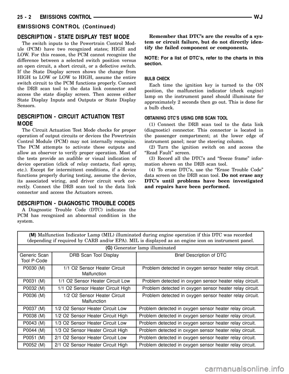
DESCRIPTION - DIAGNOSTIC TROUBLE CODES
A Diagnostic Trouble Code (DTC) indicates the
PCM has recognized an abnormal condition in the
system.Remember that DTC's are the results of a sys-
tem or circuit failure, but do not directly iden-
tify the failed component or components.
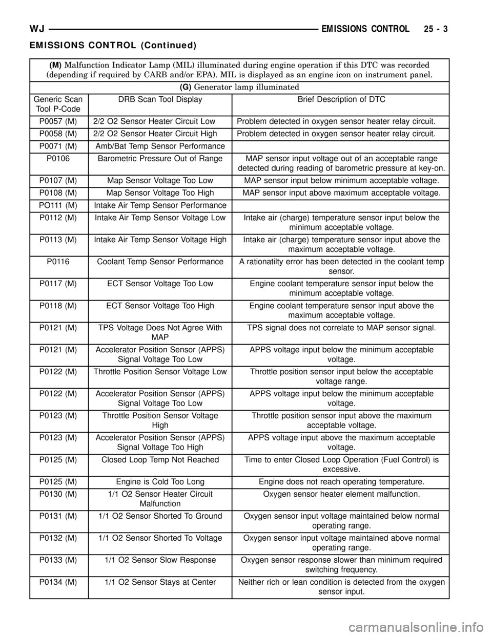
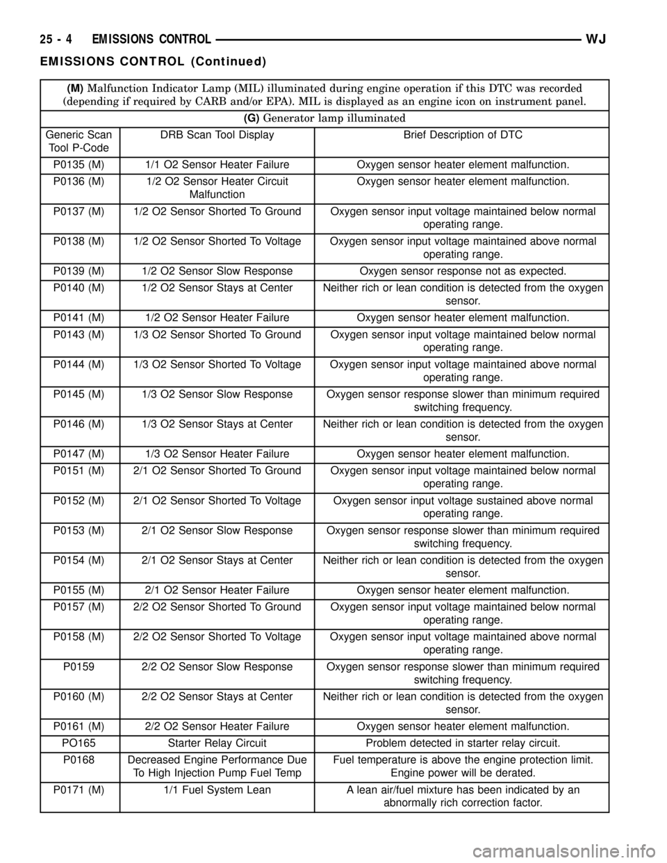
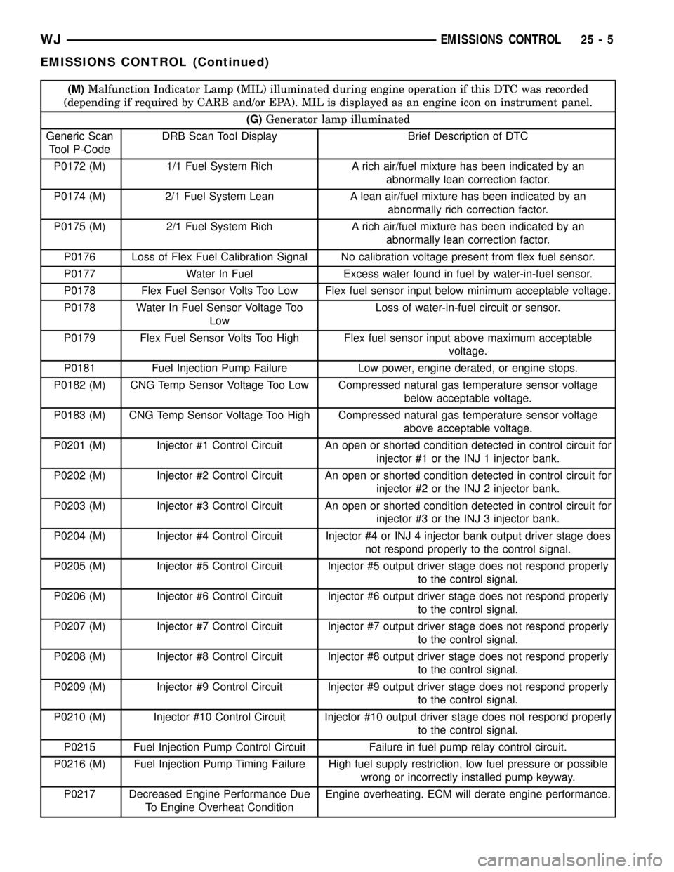
NOTE: For a list of DTC's, refer to the charts in this
section.
BULB CHECK
Each time the ignition key is turned to the ON
position, the malfunction indicator (check engine)
lamp on the instrument panel should illuminate for
approximately 2 seconds then go out. This is done for
a bulb check.
OBTAINING DTC'S USING DRB SCAN TOOL
(1) Connect the DRB scan tool to the data link
(diagnostic) connector. This connector is located in
the passenger compartment; at the lower edge of
instrument panel; near the steering column.
(2) Turn the ignition switch on and access the
ªRead Faultº screen.
(3) Record all the DTC's and ªfreeze frameº infor-
mation shown on the DRB scan tool.
(4) To erase DTC's, use the ªErase Trouble Codeº
data screen on the DRB scan tool.Do not erase any
DTC's until problems have been investigated
and repairs have been performed.
(M)Malfunction Indicator Lamp (MIL) illuminated during engine operation if this DTC was recorded
(depending if required by CARB and/or EPA). MIL is displayed as an engine icon on instrument panel.
(G)Generator lamp illuminated
Generic Scan
Tool P-CodeDRB Scan Tool Display Brief Description of DTC
P0030 (M) 1/1 O2 Sensor Heater Circuit
MalfunctionProblem detected in oxygen sensor heater relay circuit.
P0031 (M) 1/1 O2 Sensor Heater Circuit Low Problem detected in oxygen sensor heater relay circuit.
P0032 (M) 1/1 O2 Sensor Heater Circuit High Problem detected in oxygen sensor heater relay circuit.
P0036 (M) 1/2 O2 Sensor Heater Circuit
MalfunctionProblem detected in oxygen sensor heater relay circuit.
P0037 (M) 1/2 O2 Sensor Heater Circuit Low Problem detected in oxygen sensor heater relay circuit.
P0038 (M) 1/2 O2 Sensor Heater Circuit High Problem detected in oxygen sensor heater relay circuit.
P0043 (M) 1/3 O2 Sensor Heater Circuit Low Problem detected in oxygen sensor heater relay circuit.
P0044 (M) 1/3 O2 Sensor Heater Circuit High Problem detected in oxygen sensor heater relay circuit.
P0051 (M) 2/1 O2 Sensor Heater Circuit Low Problem detected in oxygen sensor heater relay circuit.
P0052 (M) 2/1 O2 Sensor Heater Circuit High Problem detected in oxygen sensor heater relay circuit.
25 - 2 EMISSIONS CONTROLWJ
EMISSIONS CONTROL (Continued)
Page 2158 of 2199

(M)Malfunction Indicator Lamp (MIL) illuminated during engine operation if this DTC was recorded
(depending if required by CARB and/or EPA). MIL is displayed as an engine icon on instrument panel.
(G)Generator lamp illuminated
Generic Scan
Tool P-CodeDRB Scan Tool Display Brief Description of DTC
P0057 (M) 2/2 O2 Sensor Heater Circuit Low Problem detected in oxygen sensor heater relay circuit.
P0058 (M) 2/2 O2 Sensor Heater Circuit High Problem detected in oxygen sensor heater relay circuit.
P0071 (M) Amb/Bat Temp Sensor Performance
P0106 Barometric Pressure Out of Range MAP sensor input voltage out of an acceptable range
detected during reading of barometric pressure at key-on.
P0107 (M) Map Sensor Voltage Too Low MAP sensor input below minimum acceptable voltage.
P0108 (M) Map Sensor Voltage Too High MAP sensor input above maximum acceptable voltage.
PO111 (M) Intake Air Temp Sensor Performance
P0112 (M) Intake Air Temp Sensor Voltage Low Intake air (charge) temperature sensor input below the
minimum acceptable voltage.
P0113 (M) Intake Air Temp Sensor Voltage High Intake air (charge) temperature sensor input above the
maximum acceptable voltage.
P0116 Coolant Temp Sensor Performance A rationatilty error has been detected in the coolant temp
sensor.
P0117 (M) ECT Sensor Voltage Too Low Engine coolant temperature sensor input below the
minimum acceptable voltage.
P0118 (M) ECT Sensor Voltage Too High Engine coolant temperature sensor input above the
maximum acceptable voltage.
P0121 (M) TPS Voltage Does Not Agree With
MAPTPS signal does not correlate to MAP sensor signal.
P0121 (M) Accelerator Position Sensor (APPS)
Signal Voltage Too LowAPPS voltage input below the minimum acceptable
voltage.
P0122 (M) Throttle Position Sensor Voltage Low Throttle position sensor input below the acceptable
voltage range.
P0122 (M) Accelerator Position Sensor (APPS)
Signal Voltage Too LowAPPS voltage input below the minimum acceptable
voltage.
P0123 (M) Throttle Position Sensor Voltage
HighThrottle position sensor input above the maximum
acceptable voltage.
P0123 (M) Accelerator Position Sensor (APPS)
Signal Voltage Too HighAPPS voltage input above the maximum acceptable
voltage.
P0125 (M) Closed Loop Temp Not Reached Time to enter Closed Loop Operation (Fuel Control) is
excessive.
P0125 (M) Engine is Cold Too Long Engine does not reach operating temperature.
P0130 (M) 1/1 O2 Sensor Heater Circuit
MalfunctionOxygen sensor heater element malfunction.
P0131 (M) 1/1 O2 Sensor Shorted To Ground Oxygen sensor input voltage maintained below normal
operating range.
P0132 (M) 1/1 O2 Sensor Shorted To Voltage Oxygen sensor input voltage maintained above normal
operating range.
P0133 (M) 1/1 O2 Sensor Slow Response Oxygen sensor response slower than minimum required
switching frequency.
P0134 (M) 1/1 O2 Sensor Stays at Center Neither rich or lean condition is detected from the oxygen
sensor input.
WJEMISSIONS CONTROL 25 - 3
EMISSIONS CONTROL (Continued)
Page 2159 of 2199

(M)Malfunction Indicator Lamp (MIL) illuminated during engine operation if this DTC was recorded
(depending if required by CARB and/or EPA). MIL is displayed as an engine icon on instrument panel.
(G)Generator lamp illuminated
Generic Scan
Tool P-CodeDRB Scan Tool Display Brief Description of DTC
P0135 (M) 1/1 O2 Sensor Heater Failure Oxygen sensor heater element malfunction.
P0136 (M) 1/2 O2 Sensor Heater Circuit
MalfunctionOxygen sensor heater element malfunction.
P0137 (M) 1/2 O2 Sensor Shorted To Ground Oxygen sensor input voltage maintained below normal
operating range.
P0138 (M) 1/2 O2 Sensor Shorted To Voltage Oxygen sensor input voltage maintained above normal
operating range.
P0139 (M) 1/2 O2 Sensor Slow Response Oxygen sensor response not as expected.
P0140 (M) 1/2 O2 Sensor Stays at Center Neither rich or lean condition is detected from the oxygen
sensor.
P0141 (M) 1/2 O2 Sensor Heater Failure Oxygen sensor heater element malfunction.
P0143 (M) 1/3 O2 Sensor Shorted To Ground Oxygen sensor input voltage maintained below normal
operating range.
P0144 (M) 1/3 O2 Sensor Shorted To Voltage Oxygen sensor input voltage maintained above normal
operating range.
P0145 (M) 1/3 O2 Sensor Slow Response Oxygen sensor response slower than minimum required
switching frequency.
P0146 (M) 1/3 O2 Sensor Stays at Center Neither rich or lean condition is detected from the oxygen
sensor.
P0147 (M) 1/3 O2 Sensor Heater Failure Oxygen sensor heater element malfunction.
P0151 (M) 2/1 O2 Sensor Shorted To Ground Oxygen sensor input voltage maintained below normal
operating range.
P0152 (M) 2/1 O2 Sensor Shorted To Voltage Oxygen sensor input voltage sustained above normal
operating range.
P0153 (M) 2/1 O2 Sensor Slow Response Oxygen sensor response slower than minimum required
switching frequency.
P0154 (M) 2/1 O2 Sensor Stays at Center Neither rich or lean condition is detected from the oxygen
sensor.
P0155 (M) 2/1 O2 Sensor Heater Failure Oxygen sensor heater element malfunction.
P0157 (M) 2/2 O2 Sensor Shorted To Ground Oxygen sensor input voltage maintained below normal
operating range.
P0158 (M) 2/2 O2 Sensor Shorted To Voltage Oxygen sensor input voltage maintained above normal
operating range.
P0159 2/2 O2 Sensor Slow Response Oxygen sensor response slower than minimum required
switching frequency.
P0160 (M) 2/2 O2 Sensor Stays at Center Neither rich or lean condition is detected from the oxygen
sensor.
P0161 (M) 2/2 O2 Sensor Heater Failure Oxygen sensor heater element malfunction.
PO165 Starter Relay Circuit Problem detected in starter relay circuit.
P0168 Decreased Engine Performance Due
To High Injection Pump Fuel TempFuel temperature is above the engine protection limit.
Engine power will be derated.
P0171 (M) 1/1 Fuel System Lean A lean air/fuel mixture has been indicated by an
abnormally rich correction factor.
25 - 4 EMISSIONS CONTROLWJ
EMISSIONS CONTROL (Continued)
Page 2160 of 2199

(M)Malfunction Indicator Lamp (MIL) illuminated during engine operation if this DTC was recorded
(depending if required by CARB and/or EPA). MIL is displayed as an engine icon on instrument panel.
(G)Generator lamp illuminated
Generic Scan
Tool P-CodeDRB Scan Tool Display Brief Description of DTC
P0172 (M) 1/1 Fuel System Rich A rich air/fuel mixture has been indicated by an
abnormally lean correction factor.
P0174 (M) 2/1 Fuel System Lean A lean air/fuel mixture has been indicated by an
abnormally rich correction factor.
P0175 (M) 2/1 Fuel System Rich A rich air/fuel mixture has been indicated by an
abnormally lean correction factor.
P0176 Loss of Flex Fuel Calibration Signal No calibration voltage present from flex fuel sensor.
P0177 Water In Fuel Excess water found in fuel by water-in-fuel sensor.
P0178 Flex Fuel Sensor Volts Too Low Flex fuel sensor input below minimum acceptable voltage.
P0178 Water In Fuel Sensor Voltage Too
LowLoss of water-in-fuel circuit or sensor.
P0179 Flex Fuel Sensor Volts Too High Flex fuel sensor input above maximum acceptable
voltage.
P0181 Fuel Injection Pump Failure Low power, engine derated, or engine stops.
P0182 (M) CNG Temp Sensor Voltage Too Low Compressed natural gas temperature sensor voltage
below acceptable voltage.
P0183 (M) CNG Temp Sensor Voltage Too High Compressed natural gas temperature sensor voltage
above acceptable voltage.
P0201 (M) Injector #1 Control Circuit An open or shorted condition detected in control circuit for
injector #1 or the INJ 1 injector bank.
P0202 (M) Injector #2 Control Circuit An open or shorted condition detected in control circuit for
injector #2 or the INJ 2 injector bank.
P0203 (M) Injector #3 Control Circuit An open or shorted condition detected in control circuit for
injector #3 or the INJ 3 injector bank.
P0204 (M) Injector #4 Control Circuit Injector #4 or INJ 4 injector bank output driver stage does
not respond properly to the control signal.
P0205 (M) Injector #5 Control Circuit Injector #5 output driver stage does not respond properly
to the control signal.
P0206 (M) Injector #6 Control Circuit Injector #6 output driver stage does not respond properly
to the control signal.
P0207 (M) Injector #7 Control Circuit Injector #7 output driver stage does not respond properly
to the control signal.
P0208 (M) Injector #8 Control Circuit Injector #8 output driver stage does not respond properly
to the control signal.
P0209 (M) Injector #9 Control Circuit Injector #9 output driver stage does not respond properly
to the control signal.
P0210 (M) Injector #10 Control Circuit Injector #10 output driver stage does not respond properly
to the control signal.
P0215 Fuel Injection Pump Control Circuit Failure in fuel pump relay control circuit.
P0216 (M) Fuel Injection Pump Timing Failure High fuel supply restriction, low fuel pressure or possible
wrong or incorrectly installed pump keyway.
P0217 Decreased Engine Performance Due
To Engine Overheat ConditionEngine overheating. ECM will derate engine performance.
WJEMISSIONS CONTROL 25 - 5
EMISSIONS CONTROL (Continued)