2002 JEEP GRAND CHEROKEE driver seat
[x] Cancel search: driver seatPage 1185 of 2199
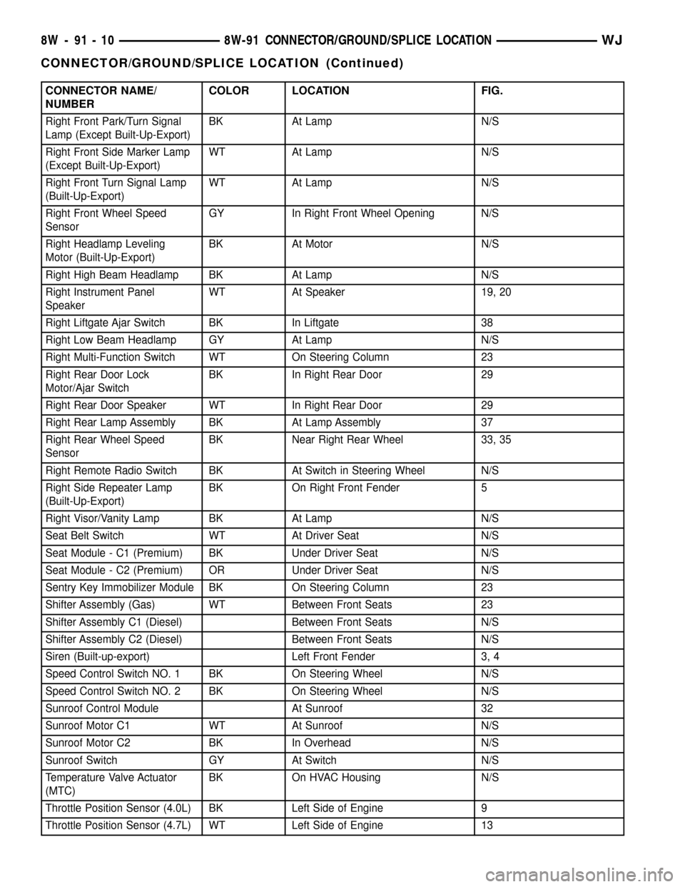
CONNECTOR NAME/
NUMBERCOLOR LOCATION FIG.
Right Front Park/Turn Signal
Lamp (Except Built-Up-Export)BK At Lamp N/S
Right Front Side Marker Lamp
(Except Built-Up-Export)WT At Lamp N/S
Right Front Turn Signal Lamp
(Built-Up-Export)WT At Lamp N/S
Right Front Wheel Speed
SensorGY In Right Front Wheel Opening N/S
Right Headlamp Leveling
Motor (Built-Up-Export)BK At Motor N/S
Right High Beam Headlamp BK At Lamp N/S
Right Instrument Panel
SpeakerWT At Speaker 19, 20
Right Liftgate Ajar Switch BK In Liftgate 38
Right Low Beam Headlamp GY At Lamp N/S
Right Multi-Function Switch WT On Steering Column 23
Right Rear Door Lock
Motor/Ajar SwitchBK In Right Rear Door 29
Right Rear Door Speaker WT In Right Rear Door 29
Right Rear Lamp Assembly BK At Lamp Assembly 37
Right Rear Wheel Speed
SensorBK Near Right Rear Wheel 33, 35
Right Remote Radio Switch BK At Switch in Steering Wheel N/S
Right Side Repeater Lamp
(Built-Up-Export)BK On Right Front Fender 5
Right Visor/Vanity Lamp BK At Lamp N/S
Seat Belt Switch WT At Driver Seat N/S
Seat Module - C1 (Premium) BK Under Driver Seat N/S
Seat Module - C2 (Premium) OR Under Driver Seat N/S
Sentry Key Immobilizer Module BK On Steering Column 23
Shifter Assembly (Gas) WT Between Front Seats 23
Shifter Assembly C1 (Diesel) Between Front Seats N/S
Shifter Assembly C2 (Diesel) Between Front Seats N/S
Siren (Built-up-export) Left Front Fender 3, 4
Speed Control Switch NO. 1 BK On Steering Wheel N/S
Speed Control Switch NO. 2 BK On Steering Wheel N/S
Sunroof Control Module At Sunroof 32
Sunroof Motor C1 WT At Sunroof N/S
Sunroof Motor C2 BK In Overhead N/S
Sunroof Switch GY At Switch N/S
Temperature Valve Actuator
(MTC)BK On HVAC Housing N/S
Throttle Position Sensor (4.0L) BK Left Side of Engine 9
Throttle Position Sensor (4.7L) WT Left Side of Engine 13
8W - 91 - 10 8W-91 CONNECTOR/GROUND/SPLICE LOCATIONWJ
CONNECTOR/GROUND/SPLICE LOCATION (Continued)
Page 1191 of 2199
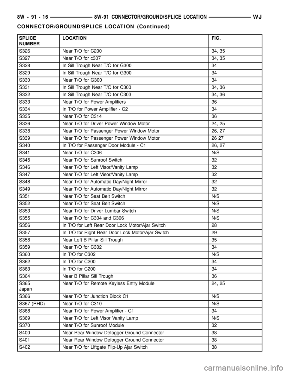
SPLICE
NUMBERLOCATION FIG.
S326 Near T/O for C200 34, 35
S327 Near T/O for c307 34, 35
S328 In Sill Trough Near T/O for G300 34
S329 In Sill Trough Near T/O for G300 34
S330 Near T/O for G300 34
S331 In Sill Trough Near T/O for C303 34, 36
S332 In Sill Trough Near T/O for C303 34, 36
S333 Near T/O for Power Amplifiers 36
S334 In T/O for Power Amplifier - C2 34
S335 Near T/O for C314 36
S336 Near T/O for Driver Power Window Motor 24, 25
S338 Near T/O for Passenger Power Window Motor 26, 27
S339 Near T/O for Passenger Power Window Motor 26 27
S340 In T/O for Passenger Door Module - C1 26, 27
S341 Near T/O for C306 N/S
S345 Near T/O for Sunroof Switch 32
S346 Near T/O for Left Visor/Vanity Lamp 32
S347 Near T/O for Left Visor/Vanity Lamp 32
S348 Near T/O for Automatic Day/Night Mirror 32
S349 Near T/O for Automatic Day/Night Mirror 32
S351 Near T/O for Seat Belt Switch N/S
S352 Near T/O for Seat Belt Switch N/S
S353 Near T/O for Driver Lumbar Switch N/S
S355 Near T/O for C304 and C306 N/S
S356 In T/O for Left Rear Door Lock Motor/Ajar Switch 28
S357 In T/O for Right Rear Door Lock Motor/Ajar Switch 29
S358 Near Left B Pillar Sill Trough 35
S359 Near T/O for C302 34
S360 In T/O for C302 N/S
S362 In T/O for C200 34
S363 In T/O for C200 34
S364 Near B Pillar Sill Trough 36
S365
JapanNear T/O for Remote Keyless Entry Module 24, 25
S366 Near T/O for Junction Block C1 N/S
S367 (RHD) Near T/O for C310 N/S
S368 Near T/O for Power Amplifier - C1 34
S369 Near T/O for Left Visor Vanity Lamp N/S
S370 Near T/O for Sunroof Module 32
S400 Near Rear Window Defogger Ground Connector 38
S401 Near Rear Window Defogger Ground Connector 38
S402 Near T/O for Liftgate Flip-Up Ajar Switch 38
8W - 91 - 16 8W-91 CONNECTOR/GROUND/SPLICE LOCATIONWJ
CONNECTOR/GROUND/SPLICE LOCATION (Continued)
Page 1360 of 2199
CRANKSHAFT OIL SEAL -
REAR
REMOVAL
NOTE: This procedure can be performed in vehicle.
(1) If being preformed in vehicle, remove the
transmission.
(2) Remove the flexplate (Refer to 9 - ENGINE/
ENGINE BLOCK/FLEX PLATE - REMOVAL).
NOTE: The crankshaft oil seal CAN NOT be reused
after removal.
NOTE: The crankshaft rear oil seal remover Special
Tool 8506 must be installed deeply into the seal.
Continue to tighten the removal tool into the seal
until the tool can not be turned farther. Failure to
install tool correctly the first time will cause tool to
pull free of seal without removing seal from engine.
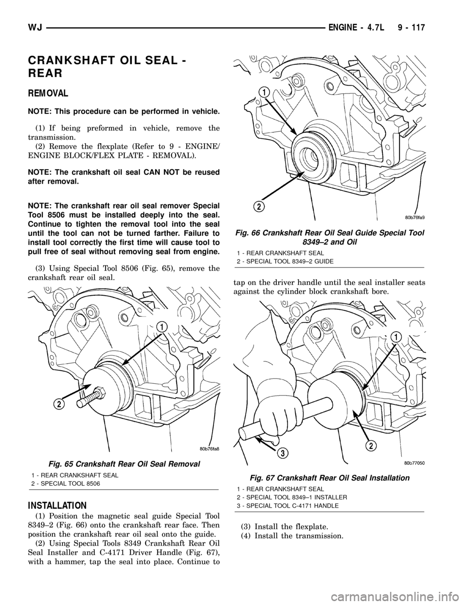
(3) Using Special Tool 8506 (Fig. 65), remove the
crankshaft rear oil seal.
INSTALLATION
(1) Position the magnetic seal guide Special Tool
8349±2 (Fig. 66) onto the crankshaft rear face. Then
position the crankshaft rear oil seal onto the guide.
(2) Using Special Tools 8349 Crankshaft Rear Oil
Seal Installer and C-4171 Driver Handle (Fig. 67),
with a hammer, tap the seal into place. Continue totap on the driver handle until the seal installer seats
against the cylinder block crankshaft bore.
(3) Install the flexplate.
(4) Install the transmission.
Fig. 65 Crankshaft Rear Oil Seal Removal
1 - REAR CRANKSHAFT SEAL
2 - SPECIAL TOOL 8506
Fig. 66 Crankshaft Rear Oil Seal Guide Special Tool
8349±2 and Oil
1 - REAR CRANKSHAFT SEAL
2 - SPECIAL TOOL 8349±2 GUIDE
Fig. 67 Crankshaft Rear Oil Seal Installation
1 - REAR CRANKSHAFT SEAL
2 - SPECIAL TOOL 8349±1 INSTALLER
3 - SPECIAL TOOL C-4171 HANDLE
WJENGINE - 4.7L 9 - 117
Page 1485 of 2199
REMOVAL
WARNING: BEFORE SERVICING THE STEERING
COLUMN THE AIRBAG SYSTEM MUST BE DIS-
ARMED. FAILURE TO DO SO MAY RESULT IN ACCI-
DENTAL DEPLOYMENT OF THE AIRBAG AND
POSSIBLE PERSONAL INJURY.(Refer to 8 - ELEC-
TRICAL/RESTRAINTS/DRIVER AIRBAG - REMOVAL).
(1) Position front wheels straight ahead.
(2) Disconnect and isolate the negative (ground)
cable from the battery.
(3) Remove the airbag,(Refer to 8 - ELECTRICAL/
RESTRAINTS/DRIVER AIRBAG - REMOVAL).
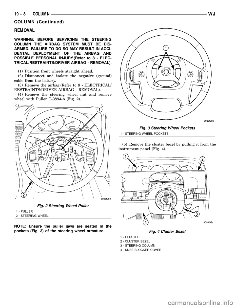
(4) Remove the steering wheel nut and remove
wheel with Puller C-3894-A (Fig. 2).
NOTE: Ensure the puller jaws are seated in the
pockets (Fig. 3) of the steering wheel armature.(5) Remove the cluster bezel by pulling it from the
instrument panel (Fig. 4).
Fig. 2 Steering Wheel Puller
1 - PULLER
2 - STEERING WHEEL
Fig. 3 Steering Wheel Pockets
1 - STEERING WHEEL POCKETS
Fig. 4 Cluster Bezel
1 - CLUSTER
2 - CLUSTER BEZEL
3 - STEERING COLUMN
4 - KNEE BLOCKER COVER
19 - 8 COLUMNWJ
COLUMN (Continued)
Page 1490 of 2199
necessary, the steering column assembly must be
replaced,(Refer to 19 - STEERING/COLUMN -
REMOVAL).
REMOVAL
IGNITION SWITCH REMOVAL
The ignition key must be in the key cylinder for
cylinder removal. The key cylinder must be removed
first before removing ignition switch.
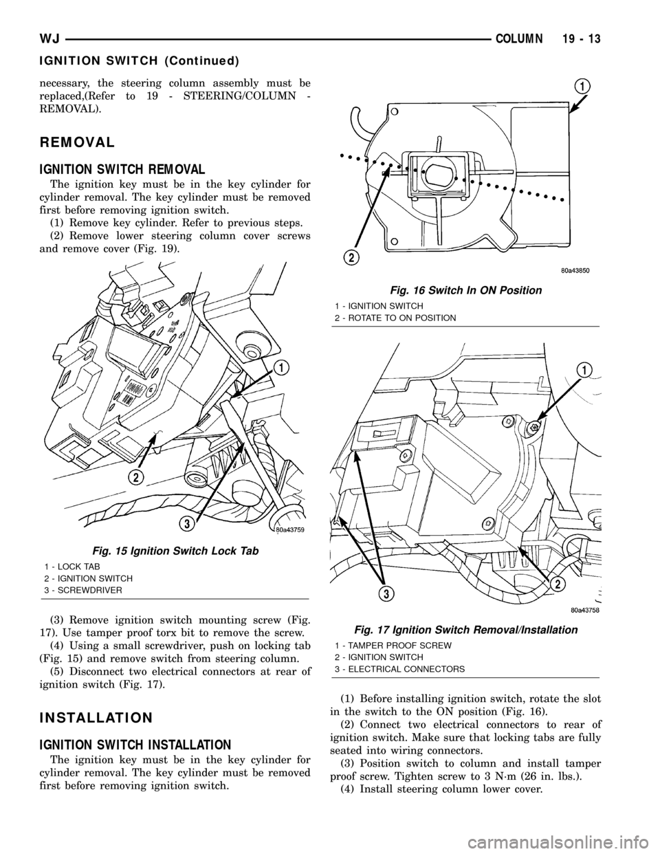
(1) Remove key cylinder. Refer to previous steps.
(2) Remove lower steering column cover screws
and remove cover (Fig. 19).
(3) Remove ignition switch mounting screw (Fig.
17). Use tamper proof torx bit to remove the screw.
(4) Using a small screwdriver, push on locking tab
(Fig. 15) and remove switch from steering column.
(5) Disconnect two electrical connectors at rear of
ignition switch (Fig. 17).
INSTALLATION
IGNITION SWITCH INSTALLATION
The ignition key must be in the key cylinder for
cylinder removal. The key cylinder must be removed
first before removing ignition switch.(1) Before installing ignition switch, rotate the slot
in the switch to the ON position (Fig. 16).
(2) Connect two electrical connectors to rear of
ignition switch. Make sure that locking tabs are fully
seated into wiring connectors.
(3) Position switch to column and install tamper
proof screw. Tighten screw to 3 N´m (26 in. lbs.).
(4) Install steering column lower cover.
Fig. 15 Ignition Switch Lock Tab
1 - LOCK TAB
2 - IGNITION SWITCH
3 - SCREWDRIVER
Fig. 16 Switch In ON Position
1 - IGNITION SWITCH
2 - ROTATE TO ON POSITION
Fig. 17 Ignition Switch Removal/Installation
1 - TAMPER PROOF SCREW
2 - IGNITION SWITCH
3 - ELECTRICAL CONNECTORS
WJCOLUMN 19 - 13
IGNITION SWITCH (Continued)
Page 1498 of 2199
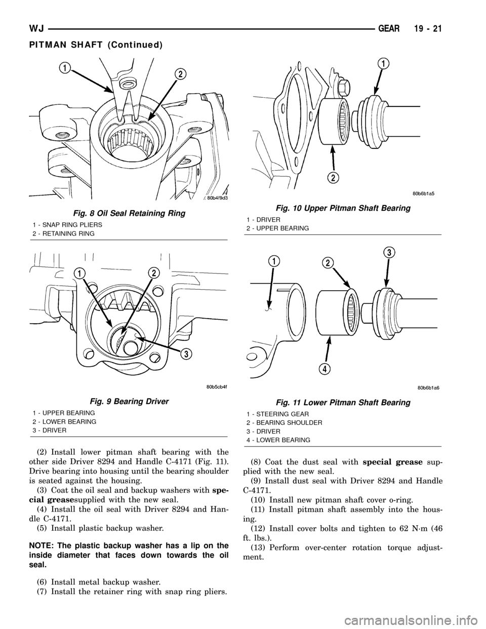
(2) Install lower pitman shaft bearing with the
other side Driver 8294 and Handle C-4171 (Fig. 11).
Drive bearing into housing until the bearing shoulder
is seated against the housing.
(3) Coat the oil seal and backup washers withspe-
cial greasesupplied with the new seal.
(4) Install the oil seal with Driver 8294 and Han-
dle C-4171.
(5) Install plastic backup washer.
NOTE: The plastic backup washer has a lip on the
inside diameter that faces down towards the oil
seal.
(6) Install metal backup washer.
(7) Install the retainer ring with snap ring pliers.(8) Coat the dust seal withspecial greasesup-
plied with the new seal.
(9) Install dust seal with Driver 8294 and Handle
C-4171.
(10) Install new pitman shaft cover o-ring.
(11) Install pitman shaft assembly into the hous-
ing.
(12) Install cover bolts and tighten to 62 N´m (46
ft. lbs.).
(13) Perform over-center rotation torque adjust-
ment.
Fig. 8 Oil Seal Retaining Ring
1 - SNAP RING PLIERS
2 - RETAINING RING
Fig. 9 Bearing Driver
1 - UPPER BEARING
2 - LOWER BEARING
3 - DRIVER
Fig. 10 Upper Pitman Shaft Bearing
1 - DRIVER
2 - UPPER BEARING
Fig. 11 Lower Pitman Shaft Bearing
1 - STEERING GEAR
2 - BEARING SHOULDER
3 - DRIVER
4 - LOWER BEARING
WJGEAR 19 - 21
PITMAN SHAFT (Continued)
Page 1499 of 2199
PITMAN SHAFT BEARING
REMOVAL
(1) Clean exposed end of pitman shaft and housing
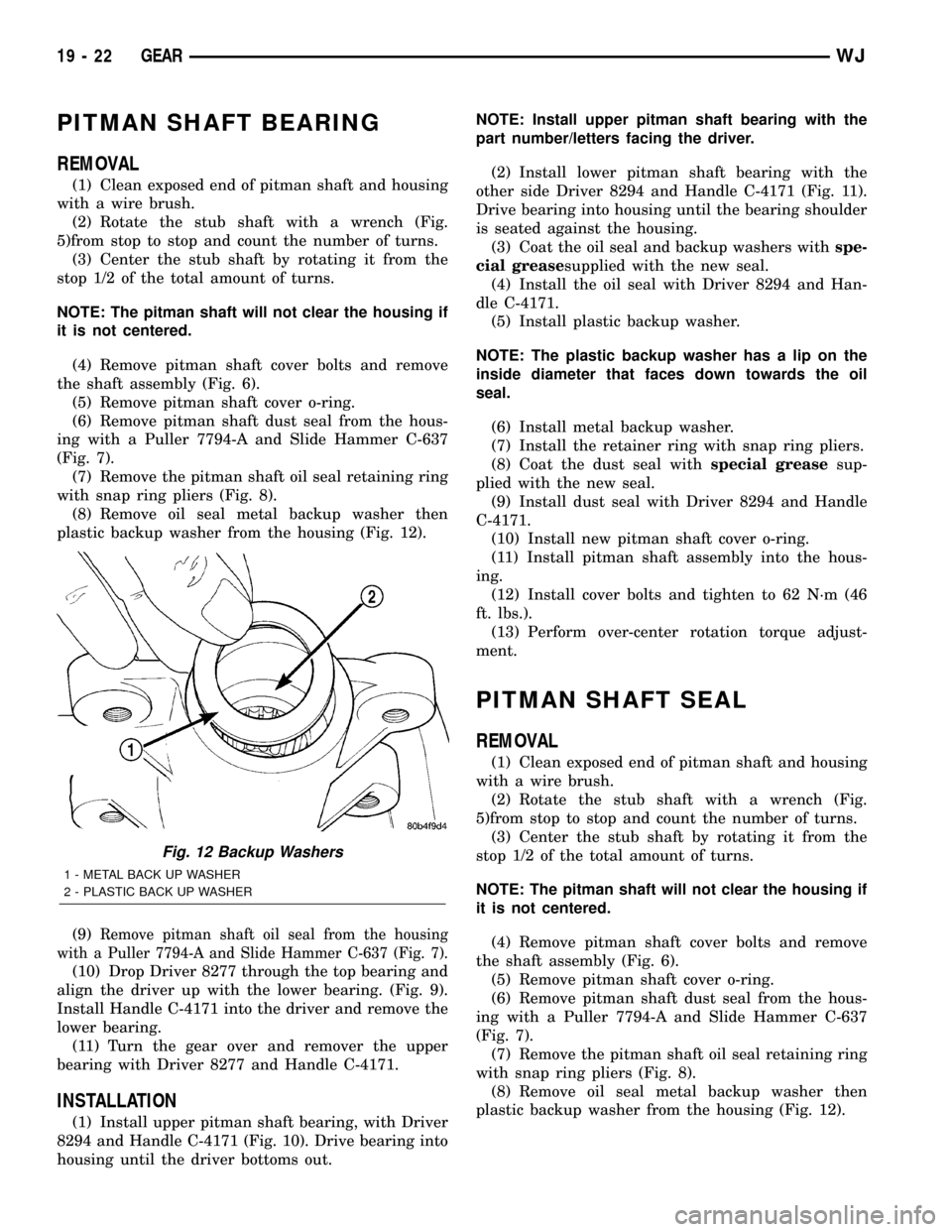
with a wire brush.
(2) Rotate the stub shaft with a wrench (Fig.
5)from stop to stop and count the number of turns.
(3) Center the stub shaft by rotating it from the
stop 1/2 of the total amount of turns.
NOTE: The pitman shaft will not clear the housing if
it is not centered.
(4) Remove pitman shaft cover bolts and remove
the shaft assembly (Fig. 6).
(5) Remove pitman shaft cover o-ring.
(6) Remove pitman shaft dust seal from the hous-
ing with a Puller 7794-A and Slide Hammer C-637
(Fig. 7).
(7) Remove the pitman shaft oil seal retaining ring
with snap ring pliers (Fig. 8).
(8) Remove oil seal metal backup washer then
plastic backup washer from the housing (Fig. 12).
(9)
Remove pitman shaft oil seal from the housing
with a Puller 7794-A and Slide Hammer C-637 (Fig. 7).
(10) Drop Driver 8277 through the top bearing and
align the driver up with the lower bearing. (Fig. 9).
Install Handle C-4171 into the driver and remove the
lower bearing.
(11) Turn the gear over and remover the upper
bearing with Driver 8277 and Handle C-4171.
INSTALLATION
(1) Install upper pitman shaft bearing, with Driver
8294 and Handle C-4171 (Fig. 10). Drive bearing into
housing until the driver bottoms out.NOTE: Install upper pitman shaft bearing with the
part number/letters facing the driver.
(2) Install lower pitman shaft bearing with the
other side Driver 8294 and Handle C-4171 (Fig. 11).
Drive bearing into housing until the bearing shoulder
is seated against the housing.
(3) Coat the oil seal and backup washers withspe-
cial greasesupplied with the new seal.
(4) Install the oil seal with Driver 8294 and Han-
dle C-4171.
(5) Install plastic backup washer.
NOTE: The plastic backup washer has a lip on the
inside diameter that faces down towards the oil
seal.
(6) Install metal backup washer.
(7) Install the retainer ring with snap ring pliers.
(8) Coat the dust seal withspecial greasesup-
plied with the new seal.
(9) Install dust seal with Driver 8294 and Handle
C-4171.
(10) Install new pitman shaft cover o-ring.
(11) Install pitman shaft assembly into the hous-
ing.
(12) Install cover bolts and tighten to 62 N´m (46
ft. lbs.).
(13) Perform over-center rotation torque adjust-
ment.
PITMAN SHAFT SEAL
REMOVAL
(1) Clean exposed end of pitman shaft and housing
with a wire brush.
(2) Rotate the stub shaft with a wrench (Fig.
5)from stop to stop and count the number of turns.
(3) Center the stub shaft by rotating it from the
stop 1/2 of the total amount of turns.
NOTE: The pitman shaft will not clear the housing if
it is not centered.
(4) Remove pitman shaft cover bolts and remove
the shaft assembly (Fig. 6).
(5) Remove pitman shaft cover o-ring.
(6) Remove pitman shaft dust seal from the hous-
ing with a Puller 7794-A and Slide Hammer C-637
(Fig. 7).
(7) Remove the pitman shaft oil seal retaining ring
with snap ring pliers (Fig. 8).
(8) Remove oil seal metal backup washer then
plastic backup washer from the housing (Fig. 12).
Fig. 12 Backup Washers
1 - METAL BACK UP WASHER
2 - PLASTIC BACK UP WASHER
19 - 22 GEARWJ
Page 1500 of 2199
(9) Remove pitman shaft oil seal from the housing
with a Puller 7794-A and Slide Hammer C-637 (Fig.
7).
(10) Drop Driver 8277 through the top bearing and
align the driver up with the lower bearing. (Fig. 9).
Install Handle C-4171 into the driver and remove the
lower bearing.
(11) Turn the gear over and remover the upper
bearing with Driver 8277 and Handle C-4171.
INSTALLATION
(1) Install upper pitman shaft bearing, with Driver
8294 and Handle C-4171 (Fig. 10). Drive bearing into
housing until the driver bottoms out.
NOTE: Install upper pitman shaft bearing with the
part number/letters facing the driver.
(2) Install lower pitman shaft bearing with the
other side Driver 8294 and Handle C-4171 (Fig. 11).
Drive bearing into housing until the bearing shoulder
is seated against the housing.
(3) Coat the oil seal and backup washers withspe-
cial greasesupplied with the new seal.
(4) Install the oil seal with Driver 8294 and Han-
dle C-4171.
(5) Install plastic backup washer.
NOTE: The plastic backup washer has a lip on the
inside diameter that faces down towards the oil
seal.
(6) Install metal backup washer.
(7) Install the retainer ring with snap ring pliers.
(8) Coat the dust seal withspecial greasesup-
plied with the new seal.
(9) Install dust seal with Driver 8294 and Handle
C-4171.
(10) Install new pitman shaft cover o-ring.
(11) Install pitman shaft assembly into the hous-
ing.
(12) Install cover bolts and tighten to 62 N´m (46
ft. lbs.).
(13) Perform over-center rotation torque adjust-
ment.
RACK PISTON/VALVE
ASSEMBLY
REMOVAL
(1) Remove the steering gear (Refer to 19 -
STEERING/GEAR - REMOVAL).
(2) Clean exposed end of pitman shaft and housing
with a wire brush.
(3) Rotate the stub shaft with a wrench (Fig.
5)from stop to stop and count the number of turns.(4) Center the stub shaft by rotating it from the
stop 1/2 of the total amount of turns.
NOTE: The pitman shaft will not clear the housing if
it is not centered.
(5) Remove pitman shaft cover bolts and remove
the shaft assembly (Fig. 6).
(6) Remove the pitman shaft cover o-ring.
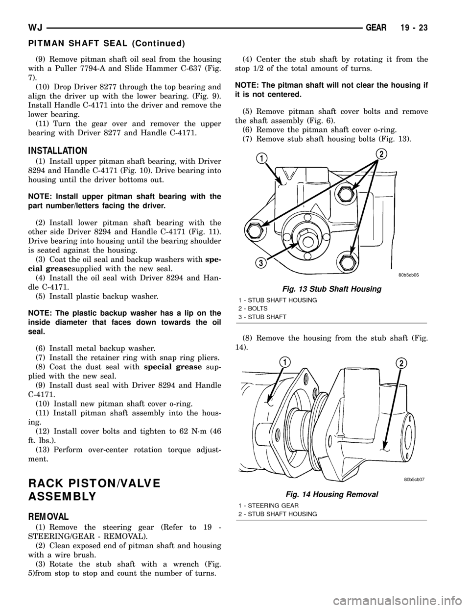
(7) Remove stub shaft housing bolts (Fig. 13).
(8) Remove the housing from the stub shaft (Fig.
14).
Fig. 13 Stub Shaft Housing
1 - STUB SHAFT HOUSING
2 - BOLTS
3 - STUB SHAFT
Fig. 14 Housing Removal
1 - STEERING GEAR
2 - STUB SHAFT HOUSING
WJGEAR 19 - 23
PITMAN SHAFT SEAL (Continued)