2002 JEEP GRAND CHEROKEE ESP
[x] Cancel search: ESPPage 1835 of 2199

OPERATION
Under normal driving conditions, the system oper-
ates conventionally, and the majority of available
torque is applied to the rear wheels. However, when
front-to-rear wheel speed variations exist, the pro-
gressive differential transfers torque to the axle with
the better traction, thus minimizing wheel spin and
maximizing control.
The key to this design is a progressive coupling
(Fig. 3), which is supplied with pressurized oil by a
gerotor style pump. The pump rotor and case are
driven by the front and rear driveshafts respectively,
and deliver pressurized oil flow to the coupling in
proportion to their speed difference. The progressive
coupling contains a multi-disc clutch pack that is
alternately splined to the front and rear driveshafts,
and controls torque variation between the front and
rear driveshafts as dictated by the pump.
A set of orifices and valves control the speed-differ-
ential starting point and rate of torque transfer rise
in the clutch. This allows the system to disregard the
normal speed differences between axles that result
from variations in front-to-rear loading and typical
cornering.
Transfer case operating ranges are selected with a
floor mounted shift lever. The shift lever is connectedto the transfer case range lever by an adjustable
cable. Range positions are marked on the shifter
bezel plate.
DIAGNOSIS AND TESTING - TRANSFER CASE - NV247
CONDITION POSSIBLE CAUSE CORRECTION
TRANSFER CASE DIFFICULT TO
SHIFT OR WILL NOT SHIFT INTO
DESIRED RANGE1. Vehicle speed too great to permit
shifting1. Reduce speed to 3-4 km/h (2-3
mph) before attempting to shift
2. Transfer case external shift cable
binding2. Lubricate, repair or replace cable,
or thighten loose components as
necessary
3. Insufficient or incorrect lubricant 3. Drain and refill to edge of fill hole
with correct lubricant
4. Internal components binding,
worn, or damaged4. Disassemble unit and replace
worn or damaged components as
necessary
TRANSFER CASE NOISY IN ALL
MODES1. Insufficient or incorrect lubricant 1. Drain and refill to edge of fill hole
with correct lubricant.If unit is still
noisy after drain and refill,
disassembly and inspection may
be required to locate source of
noise
Fig. 3 Progressive Coupling
21 - 316 TRANSFER CASE - NV247WJ
TRANSFER CASE - NV247 (Continued)
Page 1920 of 2199

REMOVAL
WARNING: ON VEHICLES EQUIPPED WITH AIR-
BAGS, DISABLE THE AIRBAG SYSTEM BEFORE
ATTEMPTING ANY STEERING WHEEL, STEERING
COLUMN, OR INSTRUMENT PANEL COMPONENT
DIAGNOSIS OR SERVICE. DISCONNECT AND ISO-
LATE THE BATTERY NEGATIVE (GROUND) CABLE,
THEN WAIT TWO MINUTES FOR THE AIRBAG SYS-
TEM CAPACITOR TO DISCHARGE BEFORE PER-
FORMING FURTHER DIAGNOSIS OR SERVICE. THIS
IS THE ONLY SURE WAY TO DISABLE THE AIRBAG
SYSTEM. FAILURE TO TAKE THE PROPER PRE-
CAUTIONS COULD RESULT IN ACCIDENTAL AIR-
BAG DEPLOYMENT AND POSSIBLE PERSONAL
INJURY.
(1) Disconnect and isolate the battery negative
cable.
(2) Roll the glove box down from the instrument
panel. (Refer to 23 - BODY/INSTRUMENT PANEL/
GLOVE BOX - STANDARD PROCEDURE - GLOVE
BOX ROLL DOWN).
NOTE: Be certain to use care not to damage or
remove the glove box hinge bumpers on the lower
instrument panel glove box opening reinforcement
when removing the glove box from the instrument
panel.
(3) Firmly grip both ends of the glove box door,
then twist and pull the door as necessary to disen-
gage the inboard hinge hook from the inboard hinge
pin on the instrument panel and reorient the hook to
the underside of the hinge pin (Fig. 18).(4) Raise the glove box door until it is perpendicu-
lar to the instrument panel.
(5) Twist the door slightly in the counterclockwise
direction and use a jiggling action to disengage the
remaining two hinge hooks from their respective
hinge pins on the instrument panel.
(6) Remove the glove box from the instrument
panel.
INSTALLATION
WARNING: ON VEHICLES EQUIPPED WITH AIR-
BAGS, DISABLE THE AIRBAG SYSTEM BEFORE
ATTEMPTING ANY STEERING WHEEL, STEERING
COLUMN, OR INSTRUMENT PANEL COMPONENT
DIAGNOSIS OR SERVICE. DISCONNECT AND ISO-
LATE THE BATTERY NEGATIVE (GROUND) CABLE,
THEN WAIT TWO MINUTES FOR THE AIRBAG SYS-
TEM CAPACITOR TO DISCHARGE BEFORE PER-
FORMING FURTHER DIAGNOSIS OR SERVICE. THIS
IS THE ONLY SURE WAY TO DISABLE THE AIRBAG
SYSTEM. FAILURE TO TAKE THE PROPER PRE-
CAUTIONS COULD RESULT IN ACCIDENTAL AIR-
BAG DEPLOYMENT AND POSSIBLE PERSONAL
INJURY.
NOTE: Be certain to use care not to damage or
remove the glove box hinge bumpers on the lower
instrument panel glove box opening reinforcement
when installing the glove box onto the instrument
panel.
(1) Position the glove box to the instrument panel
with the outboard hinge hook oriented over the out-
board hinge pin and the center hinge hook oriented
under the center hinge pin (Fig. 18).
(2) Raise the glove box door until it is perpendicu-
lar to the instrument panel.
(3) Firmly grip both ends of the glove box door and
twist the door slightly in the clockwise direction to
engage the inboard glove box hinge hook over the
inboard hinge pin on the instrument panel.
(4) Roll the glove box back up into the instrument
panel. (Refer to 23 - BODY/INSTRUMENT PANEL/
GLOVE BOX - STANDARD PROCEDURE - GLOVE
BOX ROLL DOWN).
(5) Reconnect the battery negative cable.
Fig. 18 Glove Box Remove/Install
1 - GLOVE BOX HINGE HOOKS AND HINGE PINS (3)
WJINSTRUMENT PANEL SYSTEM 23 - 47
GLOVE BOX (Continued)
Page 2093 of 2199

gap should be between 0.35 to 0.65 millimeter (0.014
to 0.026 inch). If the proper air gap is not obtained,
add or subtract shims as needed until the desired air
gap is obtained.
(9) Install the compressor shaft bolt. Tighten the
bolt to 13 N´m (115 in. lbs.).
NOTE: The shims may compress after tightening
the shaft bolt. Check the air gap in four or more
places to verify the air gap is still correct. Spin the
pulley before performing a final check of the air
gap.
(10) To complete the installation, (Refer to 24 -
HEATING & AIR CONDITIONING/PLUMBING/A/C
COMPRESSOR - INSTALLATION)
A/C COMPRESSOR CLUTCH
RELAY
DESCRIPTION
The compressor clutch relay is a International
Standards Organization (ISO) micro-relay. The termi-
nal designations and functions are the same as a con-
ventional ISO relay. However, the micro-relay
terminal orientation (footprint) is different, the cur-
rent capacity is lower, and the relay case dimensions
are smaller than those of the conventional ISO relay.
OPERATION
The compressor clutch relay is a electromechanical
device that switches battery current to the compres-
sor clutch coil when the Powertrain Control Module
(PCM) grounds the coil side of the relay. The PCM
responds to inputs from the a/c compressor switch on
the a/c heater control panel, the Automatic Zone Con-
trol (AZC) control module (if the vehicle is so
equipped), the a/c fin probe, and the a/c high pres-
sure transducer. (Refer to 24 - HEATING & AIR
CONDITIONING/CONTROLS/A/C COMPRESSOR
CLUTCH RELAY - DIAGNOSIS AND TESTING)
The compressor clutch relay is located in the Power
Distribution Center (PDC) in the engine compart-
ment. Refer to the PDC label for relay identification
and location.
The compressor clutch relay cannot be repaired
and, if faulty or damaged, it must be replaced.
DIAGNOSIS AND TESTING - A/C COMPRESSOR
CLUTCH RELAY
For circuit descriptions and diagrams, refer to the
appropriate wiring information.
The compressor clutch relay (Fig. 10) is located in
the Power Distribution Center (PDC). Refer to the
PDC label for relay identification and location.Remove the relay from the PDC to perform the fol-
lowing tests:
(1) A relay in the de-energized position should
have continuity between terminals 87A and 30, and
no continuity between terminals 87 and 30. If OK, go
to Step 2. If not OK, replace the faulty relay.
(2) Resistance between terminals 85 and 86 (elec-
tromagnet) should be 75 5 ohms. If OK, go to Step
3. If not OK, replace the faulty relay.
(3) Connect a battery to terminals 85 and 86.
There should now be continuity between terminals
30 and 87, and no continuity between terminals 87A
and 30. If OK, see the Relay Circuit Test procedure
in this group. If not OK, replace the faulty relay.
RELAY CIRCUIT TEST
For circuit descriptions and diagrams, refer to the
appropriate wiring information..
(1) The relay common feed terminal cavity (30) is
connected to fused battery feed. There should be bat-
tery voltage at the cavity for relay terminal 30 at all
times. If OK, go to Step 2. If not OK, repair the open
circuit to the fuse in the PDC as required.
(2) The relay normally closed terminal (87A) is not
used in this application. Go to Step 3.
(3) The relay normally open terminal cavity (87) is
connected to the compressor clutch coil. There should
be continuity between this cavity and the A/C com-
pressor clutch relay output circuit cavity of the com-
pressor clutch coil wire harness connector. If OK, go
to Step 4. If not OK, repair the open circuit as
required.
(4) The relay coil battery terminal (86) is con-
nected to the fused ignition switch output (run/start)
circuit. There should be battery voltage at the cavity
for relay terminal 86 with the ignition switch in the
On position. If OK, go to Step 5. If not OK, repair the
Fig. 10 A/C COMPRESSOR CLUTCH RELAY
30 - COMMON FEED
85 - COIL GROUND
86 - COIL BATTERY
87 - NORMALLY OPEN
87A - NORMALLY CLOSED
24 - 16 CONTROLSWJ
A/C COMPRESSOR CLUTCH (Continued)
Page 2096 of 2199

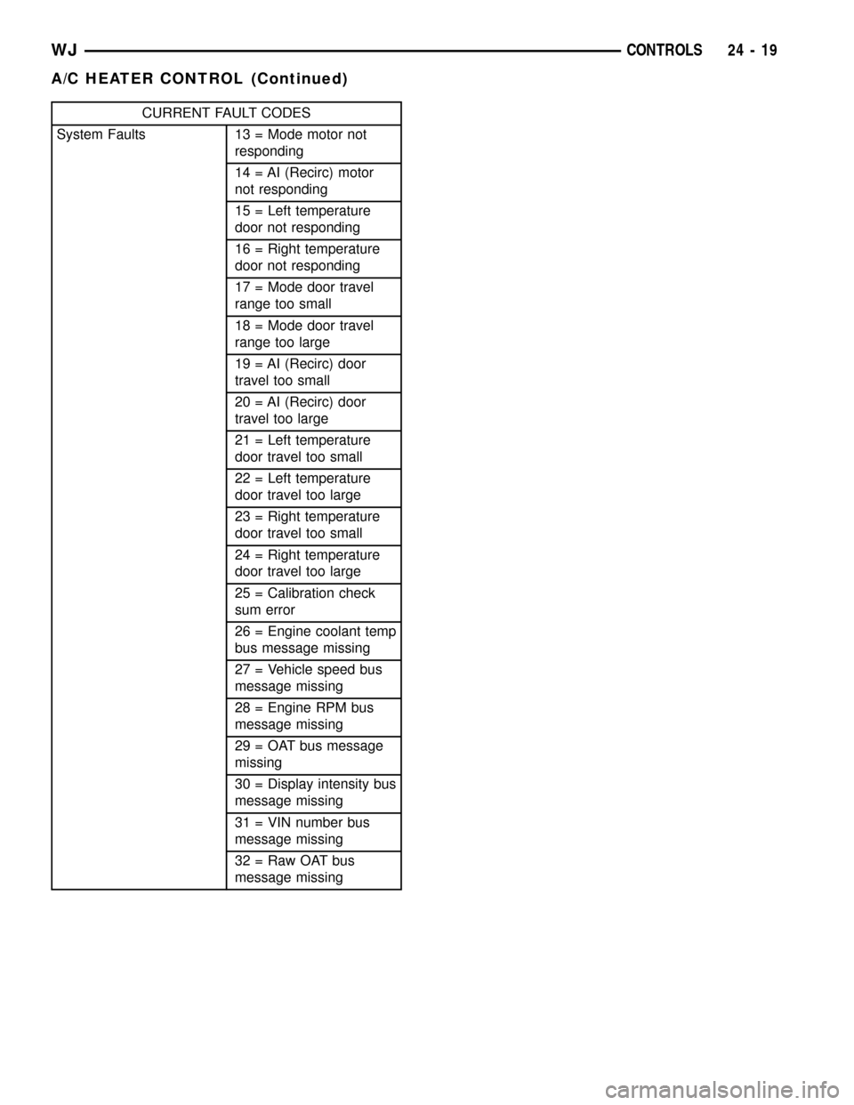
CURRENT FAULT CODES
System Faults 13 = Mode motor not
responding
14 = AI (Recirc) motor
not responding
15 = Left temperature
door not responding
16 = Right temperature
door not responding
17 = Mode door travel
range too small
18 = Mode door travel
range too large
19 = AI (Recirc) door
travel too small
20 = AI (Recirc) door
travel too large
21 = Left temperature
door travel too small
22 = Left temperature
door travel too large
23 = Right temperature
door travel too small
24 = Right temperature
door travel too large
25 = Calibration check
sum error
26 = Engine coolant temp
bus message missing
27 = Vehicle speed bus
message missing
28 = Engine RPM bus
message missing
29 = OAT bus message
missing
30 = Display intensity bus
message missing
31 = VIN number bus
message missing
32 = Raw OAT bus
message missing
WJCONTROLS 24 - 19
A/C HEATER CONTROL (Continued)
Page 2097 of 2199

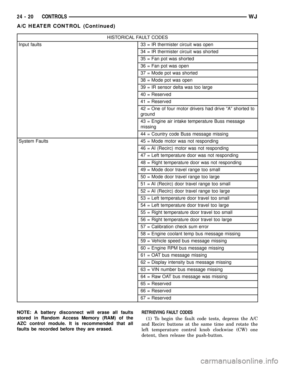
HISTORICAL FAULT CODES
Input faults 33 = IR thermister circuit was open
34 = IR thermister circuit was shorted
35 = Fan pot was shorted
36 = Fan pot was open
37 = Mode pot was shorted
38 = Mode pot was open
39 = IR sensor delta was too large
40 = Reserved
41 = Reserved
42 = One of four motor drivers had drive9A9shorted to
ground
43 = Engine air intake temperature Buss message
missing
44 = Country code Buss message missing
System Faults 45 = Mode motor was not responding
46 = AI (Recirc) motor was not responding
47 = Left temperature door was not responding
48 = Right temperature door was not responding
49 = Mode door travel range too small
50 = Mode door travel range too large
51 = AI (Recirc) door travel range too small
52 = AI (Recirc) door travel range too large
53 = Left temperature door travel too small
54 = Left temperature door travel too large
55 = Right temperature door travel too small
56 = Right temperature door travel too large
57 = Calibration check sum error
58 = Engine coolant temp bus message missing
59 = Vehicle speed bus message missing
60 = Engine RPM bus message missing
61 = OAT bus message missing
62 = Display intensity bus message missing
63 = VIN number bus message missing
64 = Raw OAT bus message was missing
65 = Reserved
66 = Reserved
67 = Reserved
NOTE: A battery disconnect will erase all faults
stored in Random Access Memory (RAM) of the
AZC control module. It is recommended that all
faults be recorded before they are erased.RETRIEVING FAULT CODES
(1) To begin the fault code tests, depress the A/C
and Recirc buttons at the same time and rotate the
left temperature control knob clockwise (CW) one
detent, then release the push-button.
24 - 20 CONTROLSWJ
A/C HEATER CONTROL (Continued)
Page 2098 of 2199

(2)If there are no fault codes, the ª00º dis-
play value will remain in the VF window.Should
there be any codes, each will be displayed for one
second in ascending numerical sequence (note: no
effort is made to display faults in the order they
occurred). The left side set temperature display will
be blanked and the right side set temperature dis-
play will indicate current and historical codes (8 his-
torical max) presently active. Once all codes have
been displayed, the system will repeat the fault code
numbers. This will continue until the left side set
temperature control is moved at least one detent
position in either direction, by pressing both the A/C
and Recirc buttons at the same time, or the ignition
is turned off. Record all of the fault codes, then see
the Current and Historical Fault Code charts for the
descriptions.
CLEARING FAULT CODES
Current faults cannot be electronically cleared.
Repair must be made to the system to eliminate the
fault causing code. Historical fault codes can be
cleared manually, or automatically. To clear a histor-
ical fault manually, depress and hold either the A/C
or Recirc button for at least three seconds while the
display is in the fault code mode of operation. Histor-
ical fault codes are cleared automatically when the
corresponding current fault code has been cleared,
and has remained cleared for a number of ignition
cycles. The faults have been cleared when two hori-
zontal bars appear in the Test Selector display.
EXITING SELF-DIAGNOSTIC MODE
The self-diagnostic mode can be exited by pressing
both the A/C and Recirc buttons at the same time, or
turning off the ignition.
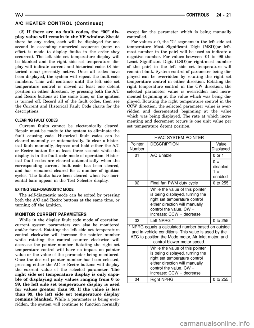
MONITOR CURRENT PARAMETERS
While in the display fault code mode of operation,
current system parameters can also be monitored
and/or forced. Rotating the left side set temperature
control clockwise will increase the pointer number
while rotating the control counter clockwise will
decrease the pointer number. Rotating the right set
temperature control will have no impact on pointer
value or the value of the parameter being monitored.
Once the desired pointer number has been selected,
pressing either the AC or Recirc buttons will display
the current value of the selected parameter.The
right side set temperature display is only capa-
ble of displaying only values ranging from 0 to
99, the left side set temperature display is used
for values greater than 99. If the value is less
than 99, the left side set temperature display
remains blanked.While a parameter is being over-
ridden, the system will continue to function normallyexcept for the parameter which is being manually
controlled.
For values < 0, the9G9segment in the left side set
temperature Most Significant Digit (MSD)(or left-
most number in the pair) will be used to indicate a
negative number. For values between -01 to -99 the
Least Significant Digit (LSD)(or right-most number
of the pair) in the left side set temperature will
remain blank. System control of parameter being dis-
played can be overridden by rotating the right set
temperature control in either direction. Rotating the
right temperature control in the CW direction, the
selected parameter value is overridden and incre-
mented beginning at the value which was being dis-
played. Rotating the right temperature control in the
CCW direction, the selected parameter value is over-
ridden and decremented beginning at the value
which was being displayed. The rate at which incre-
menting and decrement occurs is one unit value per
set temperature detent position.
HVAC SYSTEM POINTER
Pointer
NumberDESCRIPTION Value
Displayed
01 A/C Enable 0 or 1
0=
disabled
1=
enabled
02 Final fan PWM duty cycle 0 to 255
While the value of this pointer
is being displayed, turning the
right set temperature control
either direction will manually
control the value. CW =
increase; CCW = decrease
03 Left NPRG * 0 to 255
* NPRG equals a calculated number based on outside
and in-vehicle conditions. This value is used by the
AZC to position the Mode motor, Air Inlet motor, and
control blower motor speed.
While the value of this pointer
is being displayed, turning the
right set temperature control
either direction will manually
control the value. CW =
increase; CCW = decrease
04 Right NPRG 0 to 255
WJCONTROLS 24 - 21
A/C HEATER CONTROL (Continued)
Page 2102 of 2199

INSTALLATION
(1) Plug the wire harness and/or vacuum harness
connectors into the back of the a/c heater control.
(2) Position the a/c heater control in the instru-
ment panel and secure it with 4 screws. Tighten the
screws to 2.2 N´m (20 in. lbs.).
(3) Reinstall the center upper, and center lower
bezels onto the instrument panel. Refer to Instru-
ment Panel System for the procedures.
(4) Connect the battery negative cable.
A/C PRESSURE TRANSDUCER
DESCRIPTION
The A/C pressure transducer is installed on a fit-
ting located on the refrigerant discharge line near
the condenser. An internally threaded hex fitting on
the transducer connects it to the externally threaded
Schrader-type fitting on the discharge line. A rubber
O-ring seals the connection between the transducer
and the discharge line fitting. Three terminals within
a molded plastic connector receptacle on the top of
the transducer connect it to the vehicle electrical sys-
tem through a take out and connector of the head-
lamp and dash wire harness.
The A/C pressure transducer cannot be adjusted or
repaired and if faulty or damaged, it must be
replaced.
OPERATION
The A/C pressure transducer monitors the pres-
sures in the high side of the refrigerant system
through its connection to a fitting on the discharge
line. The transducer will change its internal resis-
tance in response to the pressures it monitors. The
Powertrain Control Module (PCM) provides a five
volt reference signal and a sensor ground to the
transducer, then monitors the output voltage of the
transducer on a sensor return circuit to determine
refrigerant pressure. The PCM is preporgrammed to
respond to this and other sensor inputs by controlling
the operation of the air conditioning compressor
clutch and the radiator cooling fan to help optimize
air conditioning system performance and to protect
the system components from damage. The A/C pres-
sure transducer input to the PCM will also prevent
the air conditioning compressor clutch from engaging
when the ambient temperatures are below about
0.556É C (33É F) due to the pressure/temperature
relationship of the refrigerant. The Schrader-type
valve in the liquid line fitting permits the A/C pres-
sure transducer to be removed or installed without
distrubing the refrigerant in the system. The A/C
pressure transducer is diagnosed using the DRBIIIt
scan tool. Refer to the appropriate diagnostic infor-
mation.
Fig. 13 A/C HEATER CONTROL REMOVE/INSTALL
1 - MOUNTING SCREW TABS
Fig. 14 A/C HEATER CONTROL CONNECTIONS
1 - MODE SWITCH
2 - ELECTRICAL CONNECTIONS
3 - VACUUM HARNESS
WJCONTROLS 24 - 25
A/C HEATER CONTROL (Continued)
Page 2103 of 2199

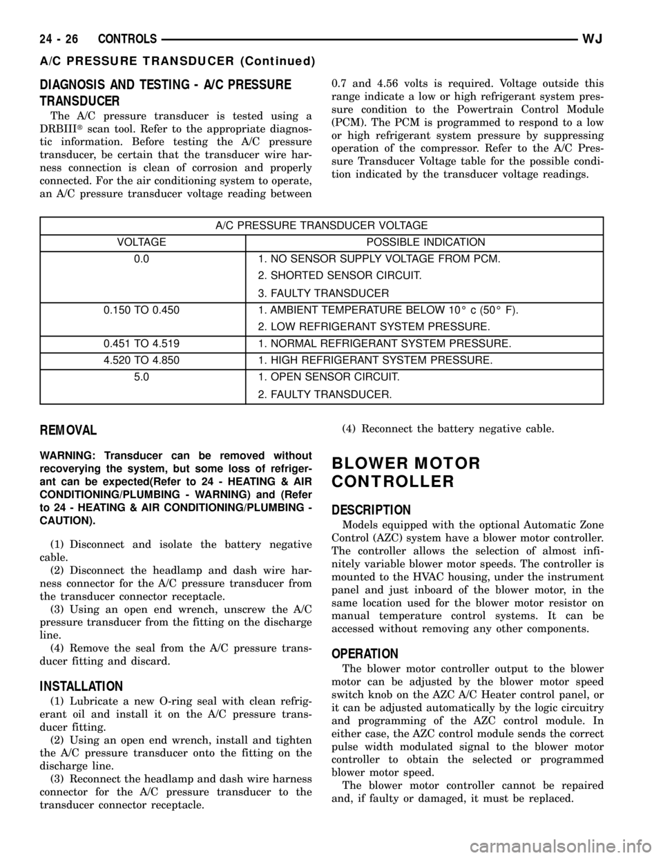
DIAGNOSIS AND TESTING - A/C PRESSURE
TRANSDUCER
The A/C pressure transducer is tested using a
DRBIIItscan tool. Refer to the appropriate diagnos-
tic information. Before testing the A/C pressure
transducer, be certain that the transducer wire har-
ness connection is clean of corrosion and properly
connected. For the air conditioning system to operate,
an A/C pressure transducer voltage reading between0.7 and 4.56 volts is required. Voltage outside this
range indicate a low or high refrigerant system pres-
sure condition to the Powertrain Control Module
(PCM). The PCM is programmed to respond to a low
or high refrigerant system pressure by suppressing
operation of the compressor. Refer to the A/C Pres-
sure Transducer Voltage table for the possible condi-
tion indicated by the transducer voltage readings.
A/C PRESSURE TRANSDUCER VOLTAGE
VOLTAGE POSSIBLE INDICATION
0.0 1. NO SENSOR SUPPLY VOLTAGE FROM PCM.
2. SHORTED SENSOR CIRCUIT.
3. FAULTY TRANSDUCER
0.150 TO 0.450 1. AMBIENT TEMPERATURE BELOW 10É c (50É F).
2. LOW REFRIGERANT SYSTEM PRESSURE.
0.451 TO 4.519 1. NORMAL REFRIGERANT SYSTEM PRESSURE.
4.520 TO 4.850 1. HIGH REFRIGERANT SYSTEM PRESSURE.
5.0 1. OPEN SENSOR CIRCUIT.
2. FAULTY TRANSDUCER.
REMOVAL
WARNING: Transducer can be removed without
recoverying the system, but some loss of refriger-
ant can be expected(Refer to 24 - HEATING & AIR
CONDITIONING/PLUMBING - WARNING) and (Refer
to 24 - HEATING & AIR CONDITIONING/PLUMBING -
CAUTION).
(1) Disconnect and isolate the battery negative
cable.
(2) Disconnect the headlamp and dash wire har-
ness connector for the A/C pressure transducer from
the transducer connector receptacle.
(3) Using an open end wrench, unscrew the A/C
pressure transducer from the fitting on the discharge
line.
(4) Remove the seal from the A/C pressure trans-
ducer fitting and discard.
INSTALLATION
(1) Lubricate a new O-ring seal with clean refrig-
erant oil and install it on the A/C pressure trans-
ducer fitting.
(2) Using an open end wrench, install and tighten
the A/C pressure transducer onto the fitting on the
discharge line.
(3) Reconnect the headlamp and dash wire harness
connector for the A/C pressure transducer to the
transducer connector receptacle.(4) Reconnect the battery negative cable.
BLOWER MOTOR
CONTROLLER
DESCRIPTION
Models equipped with the optional Automatic Zone
Control (AZC) system have a blower motor controller.
The controller allows the selection of almost infi-
nitely variable blower motor speeds. The controller is
mounted to the HVAC housing, under the instrument
panel and just inboard of the blower motor, in the
same location used for the blower motor resistor on
manual temperature control systems. It can be
accessed without removing any other components.
OPERATION
The blower motor controller output to the blower
motor can be adjusted by the blower motor speed
switch knob on the AZC A/C Heater control panel, or
it can be adjusted automatically by the logic circuitry
and programming of the AZC control module. In
either case, the AZC control module sends the correct
pulse width modulated signal to the blower motor
controller to obtain the selected or programmed
blower motor speed.
The blower motor controller cannot be repaired
and, if faulty or damaged, it must be replaced.
24 - 26 CONTROLSWJ
A/C PRESSURE TRANSDUCER (Continued)