2002 JEEP GRAND CHEROKEE brake light
[x] Cancel search: brake lightPage 5 of 2199

FASTENER USAGE
DESCRIPTION - FASTENER USAGE
WARNING: USE OF AN INCORRECT FASTENER
MAY RESULT IN COMPONENT DAMAGE OR PER-
SONAL INJURY.
Fasteners and torque specifications references in
this Service Manual are identified in metric and SAE
format.
During any maintenance or repair procedures, it is
important to salvage all fasteners (nuts, bolts, etc.)
for reassembly. If the fastener is not salvageable, a
fastener of equivalent specification must be used.
THREADED HOLE REPAIR
DESCRIPTION - THREADED HOLE REPAIR
Most stripped threaded holes can be repaired using
a Helicoilt. Follow the vehicle or Helicoiltrecommen-
dations for application and repair procedures.
INTERNATIONAL SYMBOLS
DESCRIPTION - INTERNATIONAL SYMBOLS
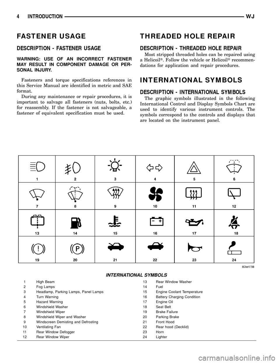
The graphic symbols illustrated in the following
International Control and Display Symbols Chart are
used to identify various instrument controls. The
symbols correspond to the controls and displays that
are located on the instrument panel.
INTERNATIONAL SYMBOLS
1 High Beam 13 Rear Window Washer
2 Fog Lamps 14 Fuel
3 Headlamp, Parking Lamps, Panel Lamps 15 Engine Coolant Temperature
4 Turn Warning 16 Battery Charging Condition
5 Hazard Warning 17 Engine Oil
6 Windshield Washer 18 Seat Belt
7 Windshield Wiper 19 Brake Failure
8 Windshield Wiper and Washer 20 Parking Brake
9 Windscreen Demisting and Defrosting 21 Front Hood
10 Ventilating Fan 22 Rear hood (Decklid)
11 Rear Window Defogger 23 Horn
12 Rear Window Wiper 24 Lighter
4 INTRODUCTIONWJ
Page 82 of 2199

INSTALLATION
(1) Pack the bearing caps 1/3 full of wheel bearing
lubricant. Apply extreme pressure (EP), lithium-base
lubricant to aid in installation.
(2) Position the spider in the yoke. Insert the seals
and bearings, then tap bearing caps into the yoke
bores far enough to hold the spider in position.
(3) Place the socket (driver) against one bearing
cap. Position the yoke with the socket in a vise.
(4) Tighten the vise to force the bearing caps into
the yoke. Force the caps enough to install the retain-
ing clips.
(5) Install the bearing cap retaining clips.
(6) Install axle shaft.
PINION SEAL
REMOVAL
(1) Raise and support the vehicle.
(2) Remove wheel and tire assemblies.
(3) Remove brake rotors and calipers, refer to 5
Brakes for procedures.
(4) Mark propeller shaft and pinion companion
flange for installation reference.
(5) Remove the propeller shaft from the pinion
companion flange.
(6) Rotate the pinion gear a minimum of ten times
and verify the pinion rotates smoothly.
(7) Record torque necessary to rotate the pinion
gear with a inch pound torque wrench.
(8) Using a short piece of pipe and Spanner
Wrench 6958 to hold the pinion companion flange
and remove the pinion nut and washer.
(9) Remove pinion companion flange with Remover
C-452 and Flange Wrench C-3281.
(10) Remove pinion seal with Remover 7794-A and
a slide hammer (Fig. 31).
INSTALLATION
(1) Apply a light coating of gear lubricant on the
lip of pinion seal. Install seal with an appropriate
installer (Fig. 32).
(2) Install pinion companion flange on the pinion
gear with Installer W-162-D, Cup 8109 and Wrench
6958.
CAUTION: Never exceed the minimum tightening
torque 298 N´m (220 ft. lbs.) while installing pinion
nut at this point. Damage to collapsible spacer or
bearings may result.
(3) Install the pinion washer and anewnut on
the pinion gear.Tighten the nut only enough to
remove the shaft end play.
Fig. 29 AXLE SHAFT OUTER U-JOINT
1 - SHAFT YOKE
2 - BEARING CAP
3 - SNAP RINGS
4 - BEARING CAP
5 - SPINDLE YOKE
6 - BEARING
7 - BEARING CAP
8 - SNAP RINGS
9 - BEARING CAP
Fig. 30 YOKE BEARING CAP
1 - LARGE-DIAMETER SOCKET
2 - VISE
3 - SMALL-DIAMETER SOCKET
WJFRONT AXLE - 186FBI 3 - 37
AXLE - U-JOINT (Continued)
Page 84 of 2199

(6) Install propeller shaft with installation refer-
ence marks aligned.
(7) Fill differential with gear lubricant.
(8) Install brake rotors and calipers.
(9) Install wheel and tire assemblies.
(10) Lower the vehicle.
COLLAPSIBLE SPACER
REMOVAL
(1) Raise and support the vehicle.
(2) Remove wheel and tire assemblies.
(3) Remove brake rotors and calipers. Refer to 5
Brakes for procedures.
(4) Mark the propeller shaft and pinion companion
flange for installation reference.
(5) Remove propeller shaft from the pinion com-
panion flange.
(6) Rotate pinion gear a minimum of ten times and
verify pinion rotates smoothly.
(7) Record pinion gear rotating torque with a
torque wrench for installation reference.
(8) Remove pinion nut and washer. Using a short
piece of pipe and Spanner Wrench 6958 to hold the
pinion companion flange.
(9) Remove pinion companion flange with Remover
C-452 and Flange Wrench C-3281.
(10) Remove pinion shaft seal with Remover
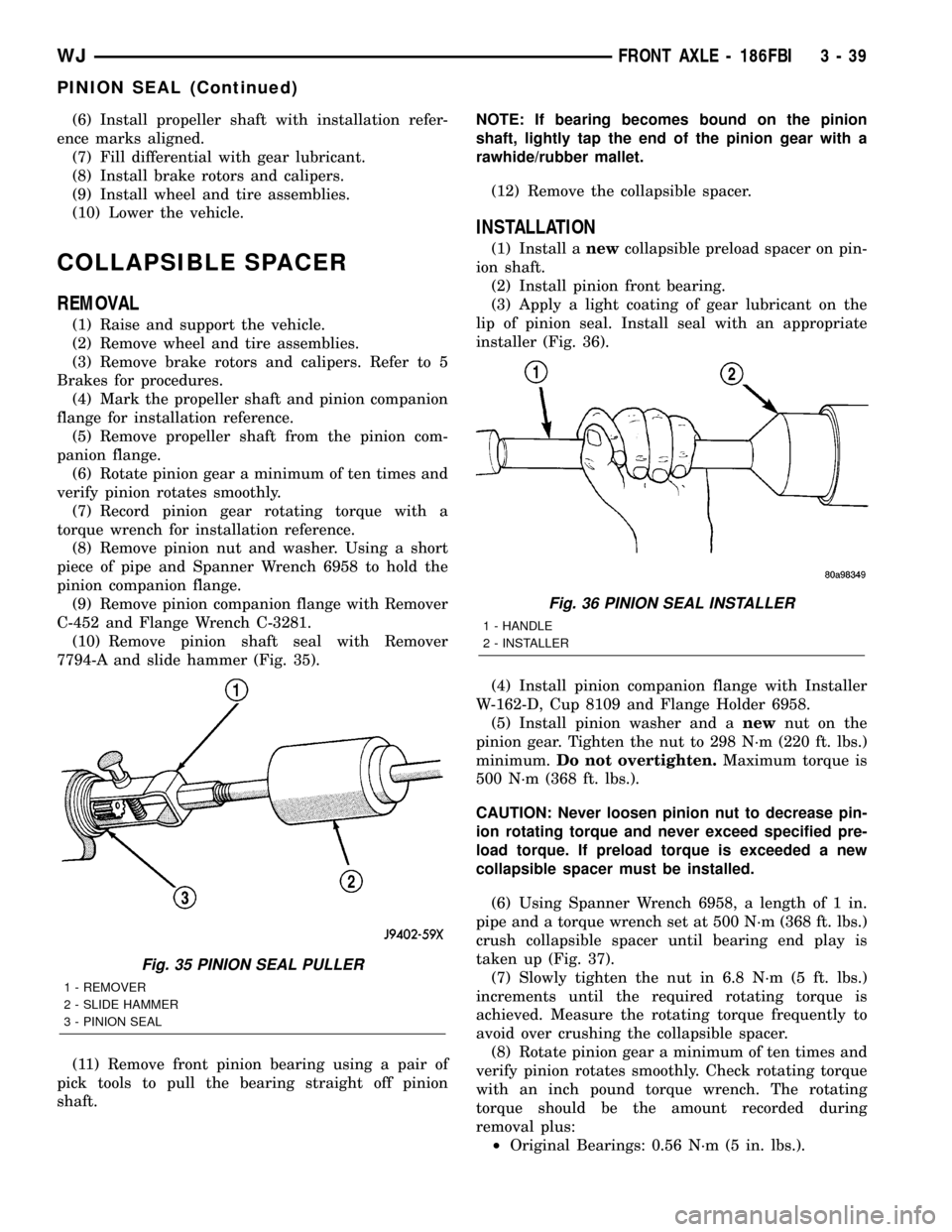
7794-A and slide hammer (Fig. 35).
(11) Remove front pinion bearing using a pair of
pick tools to pull the bearing straight off pinion
shaft.NOTE: If bearing becomes bound on the pinion
shaft, lightly tap the end of the pinion gear with a
rawhide/rubber mallet.
(12) Remove the collapsible spacer.
INSTALLATION
(1) Install anewcollapsible preload spacer on pin-
ion shaft.
(2) Install pinion front bearing.
(3) Apply a light coating of gear lubricant on the
lip of pinion seal. Install seal with an appropriate
installer (Fig. 36).
(4) Install pinion companion flange with Installer
W-162-D, Cup 8109 and Flange Holder 6958.
(5) Install pinion washer and anewnut on the
pinion gear. Tighten the nut to 298 N´m (220 ft. lbs.)
minimum.Do not overtighten.Maximum torque is
500 N´m (368 ft. lbs.).
CAUTION: Never loosen pinion nut to decrease pin-
ion rotating torque and never exceed specified pre-
load torque. If preload torque is exceeded a new
collapsible spacer must be installed.
(6) Using Spanner Wrench 6958, a length of 1 in.
pipe and a torque wrench set at 500 N´m (368 ft. lbs.)
crush collapsible spacer until bearing end play is
taken up (Fig. 37).
(7) Slowly tighten the nut in 6.8 N´m (5 ft. lbs.)
increments until the required rotating torque is
achieved. Measure the rotating torque frequently to
avoid over crushing the collapsible spacer.
(8) Rotate pinion gear a minimum of ten times and
verify pinion rotates smoothly. Check rotating torque
with an inch pound torque wrench. The rotating
torque should be the amount recorded during
removal plus:
²Original Bearings: 0.56 N´m (5 in. lbs.).
Fig. 35 PINION SEAL PULLER
1 - REMOVER
2 - SLIDE HAMMER
3 - PINION SEAL
Fig. 36 PINION SEAL INSTALLER
1 - HANDLE
2 - INSTALLER
WJFRONT AXLE - 186FBI 3 - 39
PINION SEAL (Continued)
Page 85 of 2199

²New Bearings: 1.7 to 3.4 N´m (15 to 30 in. lbs.).
(9) Install propeller shaft with reference marks
aligned.
(10) Install brake rotors and calipers.
(11) Add gear lubricant if necessary.
(12) Install wheel and tire assemblies.
(13) Lower vehicle.
DIFFERENTIAL
REMOVAL
(1) Raise and support the vehicle.
(2) Remove lubricant fill hole plug from the differ-
ential housing cover.
(3) Remove differential cover and drain lubricant.
(4) Clean the housing cavity with a flushing oil,
light engine oil or lint free cloth.Never use water,
steam, kerosene or gasoline for cleaning.
(5) Remove hub bearings and axle shafts.
(6) Note installation reference letters stamped on
the bearing caps and housing machined sealing sur-
face (Fig. 38).
(7) Loosen the differential bearing cap bolts.
(8) Position Spreader W-129-B with Adapter Kit
6987B on differential locating holes (Fig. 39). Install
hold down clamps and tighten the tool turnbuckle
finger-tight.
Fig. 37 PINION COMPANION FLANGE
1 - COMPANION FLNAGE
2 - DIFFERENTIAL HOUSING
3 - SPANNER WRENCH
Fig. 38 BEARING CAP IDENTIFICATION
1 - REFERENCE LETTERS
2 - REFERENCE LETTERS
Fig. 39 DIFFERENTIAL SPREADER LOCATION
1 - DIFFERENTIAL HOUSING
2 - ADAPTER
3 - HOLD DOWN CLAMPS
4 - SPREADER
5 - TURNBUCKLE
3 - 40 FRONT AXLE - 186FBIWJ
COLLAPSIBLE SPACER (Continued)
Page 116 of 2199

(7) Press metal retaining ring onto axle shaft with
Installer 7913 and a press (Fig. 30).
(8) Install axle in vehicle.
PINION SEAL
REMOVAL
(1) Raise and support the vehicle.
(2) Remove wheel and tire assemblies.
(3) Remove brake calipers and rotors.
(4) Mark propeller shaft and pinion yoke for
installation reference.
(5) Remove propeller shaft from the yoke.
(6) Rotate pinion gear a minimum of ten times and
verify pinion rotates smoothly.
(7) Record rotating torque of the pinion gear with
an inch pound dial-type torque wrench, for installa-
tion reference.
(8) Hold the pinion yoke with Spanner Wrench
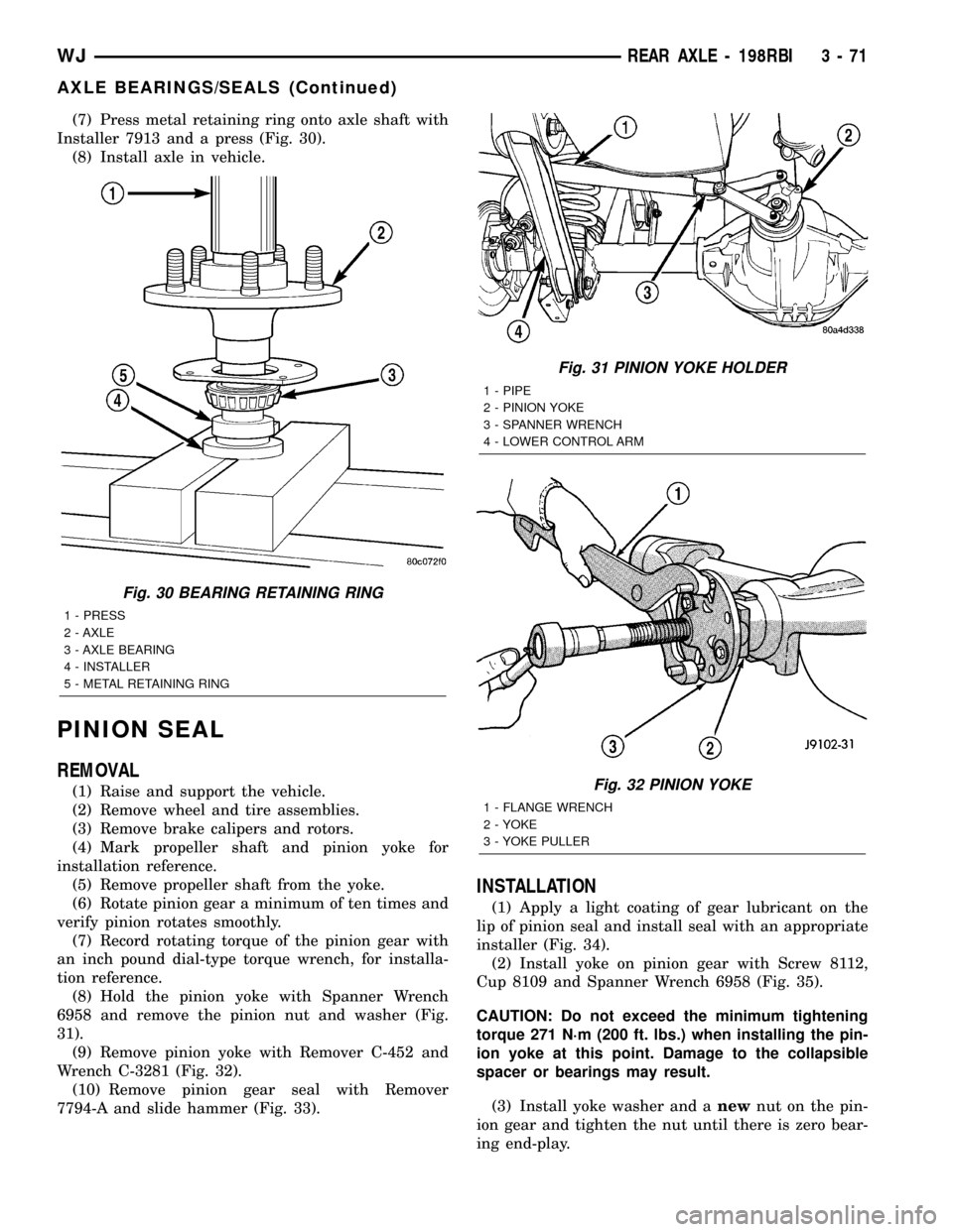
6958 and remove the pinion nut and washer (Fig.
31).
(9) Remove pinion yoke with Remover C-452 and
Wrench C-3281 (Fig. 32).
(10) Remove pinion gear seal with Remover
7794-A and slide hammer (Fig. 33).
INSTALLATION
(1) Apply a light coating of gear lubricant on the
lip of pinion seal and install seal with an appropriate
installer (Fig. 34).
(2) Install yoke on pinion gear with Screw 8112,
Cup 8109 and Spanner Wrench 6958 (Fig. 35).
CAUTION: Do not exceed the minimum tightening
torque 271 N´m (200 ft. lbs.) when installing the pin-
ion yoke at this point. Damage to the collapsible
spacer or bearings may result.
(3) Install yoke washer and anewnut on the pin-
ion gear and tighten the nut until there is zero bear-
ing end-play.
Fig. 30 BEARING RETAINING RING
1 - PRESS
2 - AXLE
3 - AXLE BEARING
4 - INSTALLER
5 - METAL RETAINING RING
Fig. 31 PINION YOKE HOLDER
1 - PIPE
2 - PINION YOKE
3 - SPANNER WRENCH
4 - LOWER CONTROL ARM
Fig. 32 PINION YOKE
1 - FLANGE WRENCH
2 - YOKE
3 - YOKE PULLER
WJREAR AXLE - 198RBI 3 - 71
AXLE BEARINGS/SEALS (Continued)
Page 118 of 2199

(6) If the rotating torque is low, use Spanner
Wrench 6958 to hold the pinion yoke (Fig. 37), and
tighten the pinion nut in 6.8 N´m (5 ft. lbs.) incre-
ments until the proper rotating torque is achieved.
CAUTION: If maximum tightening torque is reached
prior to reaching required rotating torque, the col-
lapsible spacer may have been damaged. Replace
the collapsible spacer.
(7) Install the propeller shaft with reference marks
aligned.
(8) Add gear lubricant to the differential if neces-
sary.
(9) Install brake rotors and calipers.
(10) Install wheel and tire assemblies.
(11) Lower the vehicle.
COLLAPSIBLE SPACER
REMOVAL
(1) Raise and support the vehicle.
(2) Remove wheel and tire assemblies.
(3) Remove rear brake calipers and rotors.
(4) Mark propeller shaft and pinion yoke for
installation reference and remove propeller shaft.
(5) Rotate pinion gear a minimum of ten times and
verify pinion rotates smoothly.
(6) Record rotate torque of the pinion gear, with an
inch pound torque wrench.
(7) Hold pinion yoke with Spanner Wrench 6958
and remove pinion nut and washer (Fig. 38).
(8) Remove pinion yoke with Remover C-452 and
Wrench C-3281 (Fig. 39).(9) Remove pinion shaft seal with Remover 7794-A
and slide hammer (Fig. 40).
(10) Remove front pinion bearing using a pair of
pick tools to pull the bearing off the pinion gear
shaft.
NOTE: If the pinion bearing becomes bound on the
pinion shaft, lightly tap the end of the shaft with a
rawhide/rubber mallet.
(11) Remove the collapsible spacer.
INSTALLATION
(1) Install anewcollapsible spacer on pinion
shaft.
(2) Install pinion front bearing on the pinion shaft.
Fig. 37 PINION SHAFT NUT
1 - SPANNER WRENCH
2 - PIPE
3 - TORQUE WRENCH
Fig. 38 PINION YOKE HOLDER
1 - 1 in. PIPE
2 - PINION YOKE
3 - SPANNER WRENCH
4 - LOWER CONTROL ARM
Fig. 39 PINION YOKE PULLER
1 - WRENCH
2 - PINION YOKE
3 - PULLER
WJREAR AXLE - 198RBI 3 - 73
PINION SEAL (Continued)
Page 120 of 2199

(7) Check rotating torque with an inch pound
torque wrench (Fig. 44). The rotating torque of the
pinion gear should be, the reading recorded during
removal plus an additional 0.56 N´m (5 in. lbs.).
(8) Install propeller shaft with reference marks
align.
(9) Install rear brake calipers and rotors (Refer to
5 - BRAKES/HYDRAULIC/MECHANICAL/ROTORS
- INSTALLATION).
(10) Add gear lubricant, if necessary.
(11) Install wheel and tire assemblies.
(12) Remove supports and lower vehicle.
DIFFERENTIAL
REMOVAL
(1) Raise and support vehicle.
(2) Remove fill hole plug from the differential
housing cover.
(3) Remove differential housing cover and drain
fluid.
(4) Clean the housing cavity with flushing oil, light
engine oil or lint free cloth.
NOTE: Do not use water, steam, kerosene or gaso-
line for cleaning.
(5) Remove axle shafts.(6)
Note the reference letters stamped on the bearing
caps and housing machined sealing surface (Fig. 45).
(7) Loosen the differential bearing cap bolts.
(8) Position Spreader W-129-B with Adapter Kit
6987B on differential locating holes (Fig. 46). Install
holddown clamps and tighten the turnbuckle finger-
tight.
Fig. 44 PINION ROTATING TORQUE
1 - TORQUE WRENCH
2 - PINION YOKE
Fig. 45 BEARING CAP REFERENCE
1 - REFERENCE LETTERS
2 - REFERENCE LETTERS
Fig. 46 SPREADER LOCATION
1 - DIFFERENTIAL HOUSING
2 - DOWEL
3 - SAFETY HOLD DOWN
4 - SPREADER
5 - TURNBUCKLE
WJREAR AXLE - 198RBI 3 - 75
COLLAPSIBLE SPACER (Continued)
Page 160 of 2199

NOTE: If more than 380 N´m (280 ft. lbs.) torque is
required to crush the collapsible spacer, the spacer
is defective and must be replaced.
(7) Check rotating torque with an inch pound
torque wrench (Fig. 44). The rotating torque of the
pinion gear should be, the reading recorded during
removal plus an additional 0.56 N´m (5 in. lbs.).
(8)
Install propeller shaft with reference marks align.
(9) Install rear brake rotors and calipers.
(10) Add gear lubricant, if necessary.
(11) Install wheel and tire assemblies.
(12) Remove supports and lower vehicle.
DIFFERENTIAL
REMOVAL
(1) Raise and support vehicle.
(2) Remove fill hole plug from the differential
housing cover.
(3) Remove differential housing cover and drain
fluid.
(4) Clean the housing cavity with flushing oil, light
engine oil or lint free cloth.
NOTE: Do not use water, steam, kerosene or gaso-
line for cleaning.
(5) Remove axle shafts.(6)
Note the reference letters stamped on the bearing
caps and housing machined sealing surface (Fig. 45).
(7) Loosen the differential bearing cap bolts.
(8) Position Spreader W-129-B with Adapter Kit
6987B on differential locating holes (Fig. 46). Install
holddown clamps and tighten the turnbuckle finger-
tight.
Fig. 44 PINION ROTATING TORQUE
1 - TORQUE WRENCH
2 - PINION YOKE
Fig. 45 BEARING CAP REFERENCE
1 - REFERENCE LETTERS
2 - REFERENCE LETTERS
Fig. 46 SPREADER LOCATION
1 - DIFFERENTIAL HOUSING
2 - DOWEL
3 - SAFETY HOLD DOWN
4 - SPREADER
5 - TURNBUCKLE
WJREAR AXLE - 226RBA 3 - 115
COLLAPSIBLE SPACER (Continued)