8F±32BODY STRUCTURE
General Description (Body)
This publication contains essential removal, installation,
adjustment and maintenance procedures.
Instrument Panel Assembly
Parts Location
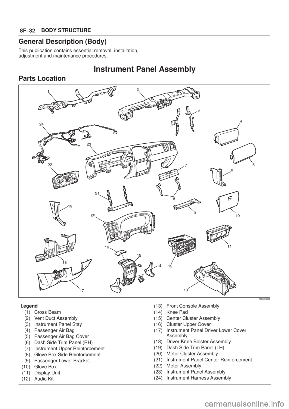
740R200024
Legend
(1) Cross Beam
(2) Vent Duct Assembly
(3) Instrument Panel Stay
(4) Passenger Air Bag
(5) Passenger Air Bag Cover
(6) Dash Side Trim Panel (RH)
(7) Instrument Upper Reinforcement
(8) Glove Box Side Reinforcement
(9) Passenger Lower Bracket
(10) Glove Box
(11) Display Unit
(12) Audio Kit(13) Front Console Assembly
(14) Knee Pad
(15) Center Cluster Assembly
(16) Cluster Upper Cover
(17) Instrument Panel Driver Lower Cover
Assembly
(18) Driver Knee Bolster Assembly
(19) Dash Side Trim Panel (LH)
(20) Meter Cluster Assembly
(21) Instrument Panel Center Reinforcement
(22) Meter Assembly
(23) Instrument Panel Assembly
(24) Instrument Harness Assembly
8F±33 BODY STRUCTURE
Removal
CAUTION: F o r p recautions on installation or
removal of SRS ± air bag system, refer to
Supplemental Restraint System (SRS) ± AIR BAG in
Restraint section.
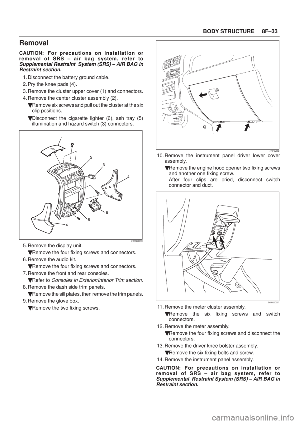
1. Disconnect the battery ground cable.
2. Pry the knee pads (4).
3. Remove the cluster upper cover (1) and connectors.
4. Remove the center cluster assembly (2).
�Remove six screws and pull out the cluster at the six
clip positions.
�Disconnect the cigarette lighter (6), ash tray (5)
illumination and hazard switch (3) connectors.
740R200008
5. Remove the display unit.
�Remove the four fixing screws and connectors.
6. Remove the audio kit.
�Remove the four fixing screws and connectors.
7. Remove the front and rear consoles.
�Refer to
Consoles in Exterior/Interior Trim section.
8. Remove the dash side trim panels.
�Remove the sill plates, then remove the trim panels.
9. Remove the glove box.
�Remove the two fixing screws.
470RW002
10. Remove the instrument panel driver lower cover
assembly.
�Remove the engine hood opener two fixing screws
and another one fixing screw.
After four clips are pried, disconnect switch
connector and duct.
610R200007
11. Remove the meter cluster assembly.
�Remove the six fixing screws and switch
connectors.
12. Remove the meter assembly.
�Remove the four fixing screws and disconnect the
connectors.
13. Remove the driver knee bolster assembly.
�Remove the six fixing bolts and screw.
14. Remove the instrument panel assembly.
CAUTION: F o r p recautions on installation or
removal of SRS ± air bag system, refer to
Supplemental Restraint System (SRS) ± AIR BAG in
Restraint section.