2002 Hyundai Getz headlight bulb
[x] Cancel search: headlight bulbPage 66 of 428
FEATURES OF YOUR HYUNDAI 1- 53
HTB018A
HTB015
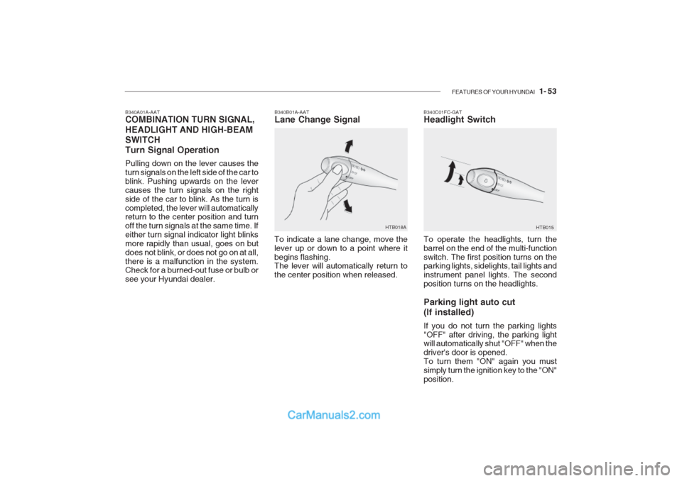
B340B01A-AAT Lane Change Signal
B340C01FC-GATHeadlight Switch
To indicate a lane change, move the lever up or down to a point where itbegins flashing. The lever will automatically return to the center position when released. To operate the headlights, turn thebarrel on the end of the multi-functionswitch. The first position turns on the parking lights, sidelights, tail lights and instrument panel lights. The secondposition turns on the headlights. Parking light auto cut (If installed) If you do not turn the parking lights "OFF" after driving, the parking light will automatically shut "OFF" when the driver's door is opened.To turn them "ON" again you mustsimply turn the ignition key to the "ON"position.
B340A01A-AAT COMBINATION TURN SIGNAL, HEADLIGHT AND HIGH-BEAM SWITCHTurn Signal Operation Pulling down on the lever causes the turn signals on the left side of the car toblink. Pushing upwards on the levercauses the turn signals on the rightside of the car to blink. As the turn iscompleted, the lever will automatically return to the center position and turn off the turn signals at the same time. Ifeither turn signal indicator light blinksmore rapidly than usual, goes on butdoes not blink, or does not go on at all,there is a malfunction in the system. Check for a burned-out fuse or bulb or see your Hyundai dealer.
Page 205 of 428

6- 32 DO-IT-YOURSELF MAINTENANCE
If the vehicle has had front body repair and the headlight assembly has been replaced, the headlight aiming should be checked using the aiming screen asshown in the illustration. Turn on the headlight switch. (Low Beam Position)
1. Adjust headlights so that main axis
of light is parallel to center line of the body and is aligned with point "P"shown in the illustration.
2. Dotted lines in the illustration show
the center of headlights.
G290B01TB-GAT Adjustment After Headlight As- sembly Replacement
SPECIFICATIONS: "H" Horizontal center line of headlightsfrom ground. : 656 mm (26.8 in.) "W" Distance between each headlight center.: 1,100 mm (43.3 in.) "L" Distance between the headlights and the wall that the lights are tested against.: 3,000 mm (118 in.).
G290B01L
LW
H
H Cut-off line
Ground line
"P"
Horizontal line15mm (0.59in.)
30mm (1.18 in.) Vertical line G270A01TB-GAT REPLACEMENT OF BULBS Headlight Bulb Before attempting to replace a head- light bulb, be sure the switch is turned to the "OFF" position.The next paragraph shows how to reach headlight bulbs so they may be changed. Be sure to replace theburned-out bulb with one of the same number and wattage rating.
CAUTION:
Keep the lamps out of contact with petroleum product, such as oil,gasoline, etc.
!
Page 206 of 428
DO-IT-YOURSELF MAINTENANCE 6- 33
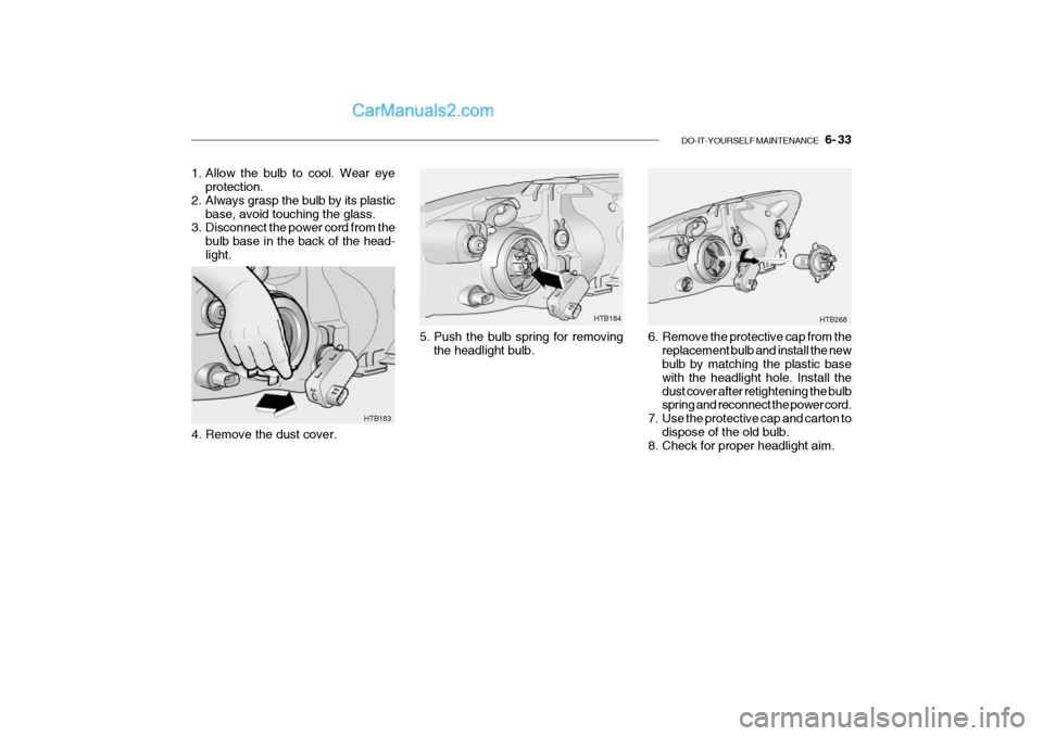
HTB183
4. Remove the dust cover.
1. Allow the bulb to cool. Wear eye
protection.
2. Always grasp the bulb by its plastic base, avoid touching the glass.
3. Disconnect the power cord from the
bulb base in the back of the head- light.
6. Remove the protective cap from thereplacement bulb and install the new bulb by matching the plastic base with the headlight hole. Install thedust cover after retightening the bulb spring and reconnect the power cord.
7. Use the protective cap and carton to
dispose of the old bulb.
8. Check for proper headlight aim.5. Push the bulb spring for removing
the headlight bulb. HTB268
HTB184
Page 207 of 428
6- 34 DO-IT-YOURSELF MAINTENANCE
!WARNING
The halogen bulb contains gas un- der pressure and if impacted could shatter, resulting in flying frag-ments. Always wear eye protection when servicing the bulb. Protect the bulb against abrasions orscratches and against liquids when lighted. Turn on the bulb only when installed in a headlight. Replacethe headlight if damaged or cracked. Keep the bulb out of the reach of children and dispose of the usedbulb with care. G270B01TB-GAT Front Turn Signal light / Position Light
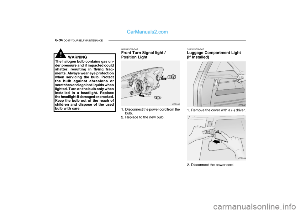
1. Disconnect the power cord from the
bulb.
2. Replace to the new bulb. HTB285G270C01TB-GAT Luggage Compartment Light (If Installed)
HTB282
1. Remove the cover with a (-) driver.
2. Disconnect the power cord. HTB283
Page 229 of 428

10- 2 INDEX
A Air Bag ...................................................................... 1-34
Air Cleaner Filter ....................................................... 6-17
Air Conditioning
Care ....................................................................... 6-22
Operation ............................................................... 1-82
Switch ..................................................................... 1-81
Air filter ............................................................ 1-83, 6-23
Antenna ................................................................... 1-107
Ashtray ...................................................................... 1-58
Auto Fuel cut Switch................................................ 1-73
B
Battery ............................................................. 2-16, 6-28 Brake Anti-lock system ..................................................... 2-13
Checking the brakes .............................................. 6-21
Fluid ....................................................................... 6-21
Pedal clearance ..................................................... 6-25
Pedal freepl ay ........................................................ 6-25
Practices ................................................................ 2-12
Breaking-In your New Hyundai ................................... 1-3
Bulbs Repl acement ................................................... 6-32
Bulbs wattage ........................................................... 6-37C
Care of Cassette Tapes ....................
..................... 1-106
Cargo area cover ...................................................... 1-70
Cassette Tape Player Operation (K220, K240, H280)
............................................................ 1-89, 1-94, 1-99
Catalytic Converter ..................................................... 7-3
Child-Protector Rear Door Lock ................................. 1-8
Child Restraint System............................................. 1-26
Cigarette Lighter ....................................................... 1-58
Clock ......................................................................... 1-58
Clutch Pedal freepl ay ........................................................ 6-24
Combination Ligh Headlight flasher .................................................... 1-54
Headlight swi tch ..................................................... 1-53
High-beam swi tch .................................................. 1-54
Lane change si gnal ................................................ 1-53
Turn signal oper ation............................................. 1-53
Compact Disc Player Operation (H 280) .................1-101
Console tray .............................................................. 1-59
Cooling Fans ............................................................. 6-29
Corrosion protection
Cleaning the interior ................................................. 4-5
Protecting your Hyundai from corrosion .................. 4-2
Washing and waxing ................................................ 4-3
Page 402 of 428
6- 28 DO-IT-YOURSELF MAINTENANCE
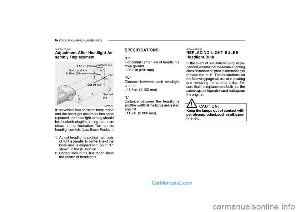
SPECIFICATIONS: "H" Horizontal center line of headlightsfrom ground. : 26.8 in.(656 mm) "W" Distance between each headlight center.: 43.3 in. (1,100 mm) "L" Distance between the headlights and the wall that the lights are tested against.: 118 in. (3,000 mm). G270A01TB-EAT REPLACING LIGHT BULBS Headlight Bulb In the event of bulb failure being expe- rienced, ensure that the relative lighting circuit is turned off prior to attempting toreplace the bulb. The illustrations on the following page will assist in locating and removing the various bulbs. En-sure that the replacement bulb has the same cap configuration and wattage as the original.
!
CAUTION:
Keep the lamps out of contact with petroleum product, such as oil, gaso- line, etc.
If the vehicle has had front body repair and the headlight assembly has been replaced, the headlight aiming should be checked using the aiming screen asshown in the illustration. Turn on the headlight switch. (Low Beam Position)
1. Adjust headlights so that main axis
of light is parallel to center line of the body and is aligned with point "P"shown in the illustration.
2. Dotted lines in the illustration show
the center of headlights.
G290B01TB-EAT Adjustment After Headlight As- sembly ReplacementG290B01L
L
W
H
H Cut-off line
Ground line
"P"
Horizontal line0.59in. (15mm)
1.18 in. (30mm) Vertical line
Page 403 of 428
DO-IT-YOURSELF MAINTENANCE 6- 29
!
HTB183
HTB268HTB184
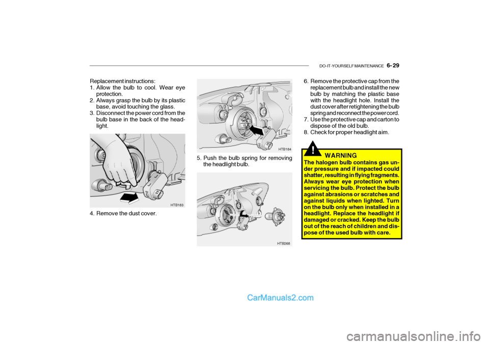
Replacement instructions:
1. Allow the bulb to cool. Wear eye
protection.
2. Always grasp the bulb by its plastic base, avoid touching the glass.
3. Disconnect the power cord from the bulb base in the back of the head-light.
4. Remove the dust cover. 5. Push the bulb spring for removing
the headlight bulb. 6. Remove the protective cap from the
replacement bulb and install the new bulb by matching the plastic basewith the headlight hole. Install the dust cover after retightening the bulb spring and reconnect the power cord.
7. Use the protective cap and carton to dispose of the old bulb.
8. Check for proper headlight aim.
WARNING
The halogen bulb contains gas un-der pressure and if impacted could shatter, resulting in flying fragments. Always wear eye protection whenservicing the bulb. Protect the bulb against abrasions or scratches and against liquids when lighted. Turnon the bulb only when installed in a headlight. Replace the headlight if damaged or cracked. Keep the bulbout of the reach of children and dis- pose of the used bulb with care.
Page 426 of 428

INDEX 10- 3
ENGINE OIL REPLENISHMENT ................................ 6-8
ENGINE OIL ............................................................... 6-6 F FRONT ASHTRAY .................................................... 1-52
FRONT SEAT ........................................................... 1-11
FRONT FOG LIGHT SWITCH .................................. 1-50
FUEL ECONOMY ....................................................... 2-7
FUEL GAUGE ........................................................... 1-41
FUEL RECOMMENDATIONS ..................................... 1-1
FUSE PANEL DESCRIPTION ..................................6-34
FUSIBLE LINKS ........................................................ 6-24
GGLOVE BOX ............................................................. 1-57
HHAZARD WARNING SYSTEM................................. 1-49
HEADLIGHT AIMING ADJUSTEMENT ....................6-27
HEADLIGHT BULB ................................................... 6-28
HEADLIGHT LEVELING DEVICE SYSTEM .............1-53
HEAD RESTRAINT ADJ USTMENT .......................... 1-12
HEATED REAR WINDOW ............. ...........................1-50
HEATING AND COOLING CONTROL .....................1-68
HEIGHT ADJUSTABLE FRONT SEAT SHOULDER BELT ................................................ 1-18
HORN ........................................................................ 1-67
HOW TO USE LUGGAGE ROOM ............................1-63I
IF THE ENGINE CANNOT BE CRANKED
................. 3-2
IF THE ENGINE OVERHEATS ................................... 3-4
IF THE ENGINE WILL NOT START ........................... 3-2
IF THE EVENT OF A PUNCTURE ............................. 3-6
IMMOBILIZER SYSTEM ............................................. 1-4
INDIVIDUAL CIRCUIT FUSES .................................6-24
INSTRUMENT CLUSTER AND INDICATO RS .........1-35
INTERIOR LIGHT ..................................................... 1-56
INTERIOR REAR VIEW MIRROR ............................ 1-59
JJUMP STARTING ....................................................... 3-3
KKEY POSITI ONS ........................................................ 2-3
LLIGHTING SW ITCH .................................................. 1-47
LUGGAGE BOARD ................................................... 1-65
LUGGAGE NET ........................................................ 1-65
LUGGAGE ROOM .................................................... 1-63
LUGGAGE UNDER TRAY .............................. .......... 1-64
LUMBAR SUPPORT ADJUSTMENT ........................1-12