Page 397 of 428
DO-IT-YOURSELF MAINTENANCE 6- 23
The various engine drive belts must be checked for condition, tension and free- dom from damage and excessive wear.The tension of a new belt must be checked after thirty minutes running following fitment of the new belt to allowfor the initial belt stretch. G190B01TB-GAT CHECKING DRIVE BELTS (Diesel)
A/C comp.
Auto tensioner Pulley
G190B01TB
AlternatorPower steering pump
At the scheduled maintenance inspec- tion, belts should be examined forcracks, wear, fraying or other evidence of deterioration and replaced if neces- sary.Belt routing should also be checked to be sure there is no interference be- tween the belts and other parts of theengine.
Crankshaft Pulley
SG190A1-E DRIVE BELTS (Gasoline)
1.1L
1.3L/1.6L Alternator
0.37 ~ 0.43 in. (9.5 ~11.0 mm)
Water Pump Pulley
Alternator Pulley
0.2~0.24 in.(5.1~6 mm)
HTB186
Crankshaft pulley
HTB220
Water Pump Pulley
Page 400 of 428

6- 26 DO-IT-YOURSELF MAINTENANCE
HTB287
SG230B1-E POWER STEERING HOSES Power steering hoses should be checked for damage, deterioration andleakage at each service.
steering fluid level is between the "MAX" and "MIN" level markings on the fluid reservoir. NOTE: Grinding noise from power steering pump may be heard immediatelyafter the engine is started in extremely
cold condition (below -4°F). If the noise stops during warm up, there isno abnormal function in the system. This is due to a power steering fluid characteristic in extremely cold con-ditions. FLUID RECOMMENDATION Only automatic transmission fluid meet- ing the specification of PSF-3 shouldbe used in the power steering system.
G300A01TB-GAT REMOVAL OF WATER FROM THE FUEL FILTER(DIESEL ENGINE) If the fuel filter warning lamp illuminates during driving, it indicates that waterhas accumulated in the fuel filter. If this occurs, remove the water as described.
SG230A1-E POWER STEERING FLUID LEVEL The power steering fluid level should be checked daily.To check the power steering fluid level, be sure the ignition is "OFF", then check to make certain that the power
HTB163
Page 408 of 428
6- 34 DO-IT-YOURSELF MAINTENANCE
G200C01TB-GAT FUSE PANEL DESCRIPTION Engine Compartment
HTB261-EPROTECTED COMPONENTS
Ignition Switch
Ignition Switch, Start Relay
Fuel pump, Alternator, ECM
Auto Fuel Cut Switch
Radiator Fan
Headlight, Defogger RelayABSECMA/CON, Fuel PumpInjectorA/Conditioner
HornABSABS
Blower, Blower Motor
Power Window
Electronic power steering AlternatorSpare Fuse Spare FuseSpare Fuse
FUSE RATING
30A30A30A20A30A50A10A10A10A15A10A10A20A40A30A30A50A 15A 10A10A
DESCRIPTION
IGN 2IGN 1ECU
F/PUMP RAD
BATT ABS
ECU
SNSR INJ
A/CON HORN ABS1ABS2 BLW
P/WDW EPS
BATT( ) SPARE
SPARE
SPARE
NOTE:
Not all fuse panel descriptions in this manual may be applicable to your vehicle. It is accurate at the time of printing. When you inspect the fuse box on your vehicle, refer to the fuse box label.
1.1L 1.3/1.6L 100A120A
Page 416 of 428
CONSUMER INFORMATION 8- 3
4.5Jx13 5.0Jx13 5.0Jx14 5.5Jx145.5Jx15
4.0Tx14 TYRE
SIZE
RIM
SIZE PRESSURE, kPa (PSI)
165/65R14
175/65R14 185/55R15
T105/70D14 REAR
210(30) 420(60) FRONT
230(33) 420(60)
UP TO 2
PERSONS UP TO
MAX. LOAD
REAR
230(33)420(60)
FRONT 210(30) 420(60)
The engine number is stamped on the engine block as shown in the drawing. I030A02TB-EAT TYRE PRESSURES In modern high-speed motoring, correct tyre pressures are vitally important.
I010B01B
HTB263
Diesel EngineIncorrect tyre pressures can affect ve- hicle safety by causing reduced adhe- sion, steering response and tyre failurethrough overheating. The tyre pressure must only be checked when the tyres are cold. The correct tyre pressures areindicated on the label affixed in the glove box and below. Tyre pressures should be increased by 3 psi when the vehicle is driven fully laden or under conditions of sustained high speed motoring.
Page 418 of 428

CONSUMER INFORMATION 8- 5
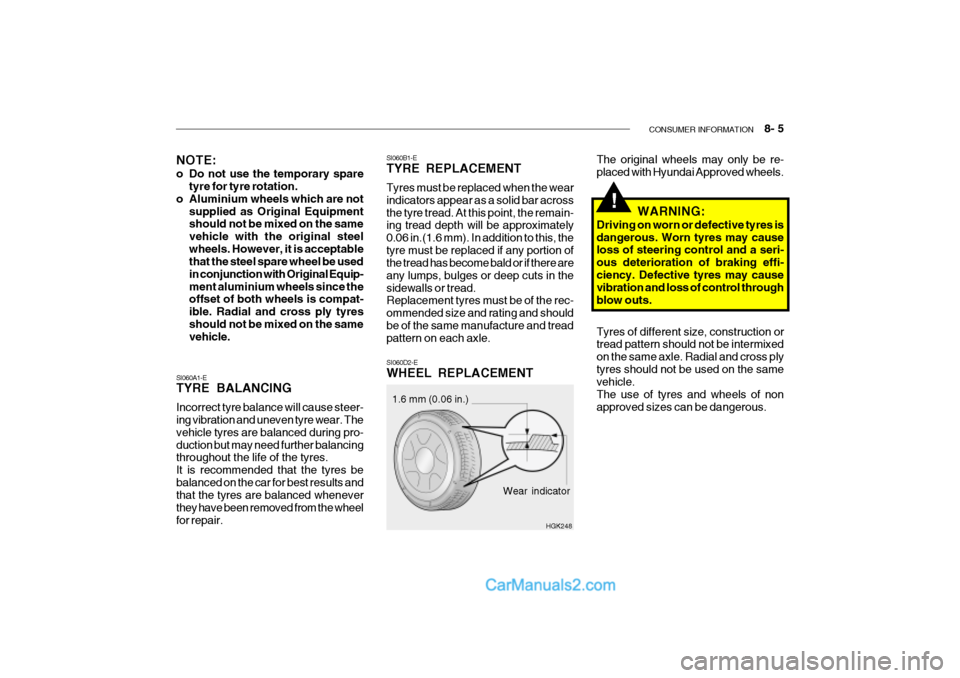
SI060B1-E TYRE REPLACEMENT Tyres must be replaced when the wear indicators appear as a solid bar acrossthe tyre tread. At this point, the remain- ing tread depth will be approximately 0.06 in.(1.6 mm). In addition to this, thetyre must be replaced if any portion of the tread has become bald or if there are any lumps, bulges or deep cuts in thesidewalls or tread. Replacement tyres must be of the rec- ommended size and rating and shouldbe of the same manufacture and tread pattern on each axle. SI060D2-E WHEEL REPLACEMENT
Wear indicator
1.6 mm (0.06 in.)
HGK248
NOTE:
o Do not use the temporary spare
tyre for tyre rotation.
o Aluminium wheels which are not
supplied as Original Equipment should not be mixed on the same vehicle with the original steelwheels. However, it is acceptable that the steel spare wheel be used in conjunction with Original Equip-ment aluminium wheels since the offset of both wheels is compat- ible. Radial and cross ply tyresshould not be mixed on the same vehicle.
SI060A1-E TYRE BALANCING Incorrect tyre balance will cause steer- ing vibration and uneven tyre wear. The vehicle tyres are balanced during pro-duction but may need further balancing throughout the life of the tyres. It is recommended that the tyres bebalanced on the car for best results and that the tyres are balanced whenever they have been removed from the wheelfor repair. The original wheels may only be re- placed with Hyundai Approved wheels.
WARNING:
Driving on worn or defective tyres is dangerous. Worn tyres may cause loss of steering control and a seri- ous deterioration of braking effi-ciency. Defective tyres may cause vibration and loss of control through blow outs. Tyres of different size, construction or tread pattern should not be intermixed on the same axle. Radial and cross plytyres should not be used on the same vehicle. The use of tyres and wheels of nonapproved sizes can be dangerous.
!
Page 421 of 428
9- 2 VEHICLE SPECIFICATIONS
1.3 L
1.6 L
Type Wheel free playRack stroke Oil pump type 150 (3,810) 65.6(1,665) 58.7(1,490) 96.7(2,455)57.1(1,450) 56.7(1,440)
Overall length Overall width Overall height (unladen) Wheel baseWheel tread J030A02TB-EAT TYRE1.1 L
13.5V,70A
Dual hydraulic with brake booster Ventilated disc DrumCable
J010A01TB-EAT MEASUREMENT
J060A01TB-DAT FUEL SYSTEM
Rack and pinion 0 ~ 1.18 in. (0 ~ 30 mm) 5.20 in. (132 mm) 5.5 in. (140 mm) Vane type
165/65R14 175/65R14, 185/55R15
StandardOption
Front Rear
mm (in.)
J020A01TB-EAT POWER STEERING
Fuel tank Capacity Litre
45 Imp.gal
9.9
J040A02TB-EAT ELECTRICAL
Item Battery Alternator
J050A01FC-GAT BRAKE Type Front brake typeRear brake type Parking brake
J035A02TB-EAT SPARE TYRE
Temporary tyre (T 150/70 D14) Full size
1.1L 1.3/1.5/1.6L
DIESEL
1.5 L
60AH
12V, 90APETROL
Manual Power 13.5V, 90A
45AH
Page 423 of 428

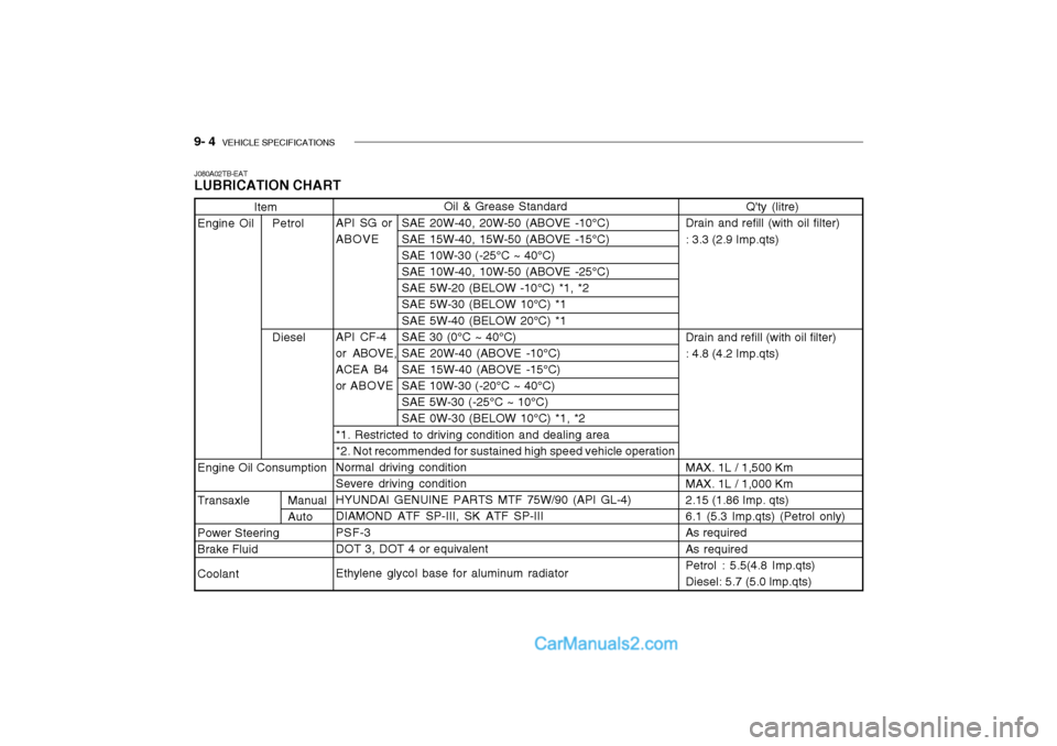
9- 4 VEHICLE SPECIFICATIONS
Oil & Grease Standard
API SG or SAE 20W-40, 20W-50 (ABOVE -10°C) ABOVE SAE 15W-40, 15W-50 (ABOVE -15°C)SAE 10W-30 (-25°C ~ 40°C) SAE 10W-40, 10W-50 (ABOVE -25°C) SAE 5W-20 (BELOW -10°C) *1, *2SAE 5W-30 (BELOW 10°C) *1 SAE 5W-40 (BELOW 20°C) *1
API CF-4 SAE 30 (0°C ~ 40°C)
or ABOVE, SAE 20W-40 (ABOVE -10°C)
ACEA B4 SAE 15W-40 (ABOVE -15°C)
or ABOVE SAE 10W-30 (-20°C ~ 40°C) SAE 5W-30 (-25°C ~ 10°C)SAE 0W-30 (BELOW 10°C) *1, *2
*1. Restricted to driving condition and dealing area*2. Not recommended for sustained high speed vehicle operationNormal driving condition Severe driving condition HYUNDAI GENUINE PARTS MTF 75W/90 (API GL-4)DIAMOND ATF SP-III, SK ATF SP-III PSF-3 DOT 3, DOT 4 or equivalent Ethylene glycol base for aluminum radiator
Item
Engine Oil Petrol Diesel
Engine Oil Consumption
Transaxle Manual Auto
Power Steering
Brake Fluid Coolant
J080A02TB-EAT LUBRICATION CHARTQ'ty (litre)
Drain and refill (with oil filter) : 3.3 (2.9 Imp.qts) Drain and refill (with oil filter) : 4.8 (4.2 Imp.qts) MAX. 1L / 1,500 Km MAX. 1L / 1,000 Km 2.15 (1.86 Imp. qts) 6.1 (5.3 Imp.qts) (Petrol only)As required As required Petrol : 5.5(4.8 Imp.qts)Diesel: 5.7 (5.0 lmp.qts)
Page 425 of 428

10- 2 INDEX
A AIR BAG ................................................................... 1-29
AIR CONDITIONING SWITCH .................................1-74
AIR CONDITIONING SYSTEM MAINTENANCE ..... 6-19
AIR CLEANER FILTER ............................................. 6-14
ANTENNA ................................................................. 1-81
ANTI-LOCK BRAKE SYSTEM .................................. 2-13
ANTI-THEFT ALARM SYSTEM .................................. 1-7
ASHTRAY ................................................................. 1-52
AUTO FUEL CUT SW ITCH...................................... 1-66
AUTOMATIC TRANSAXLE ......................................... 2-9AUTOMATIC TRANSAXLE FLUID ...........................6-16
BBATTERY MAINTENANCE ......................................6-25
BEFORE STARTING THE ENGINE ...........................2-3
BONNET RE LEASE.................................................. 1-60
BRAKE PEDAL FREEPLAY .....................................6-22
BRAKE SYSTEM CHECKING ..................................6-18
CCARE OF DISC ......................................................... 1-79
CARE OF SEAT BELTS .... .......................................1-17
CARGO AREA COVER ............................................ 1-63
CATALYTIC CONVERTOR OPERATING PRECAUTIONS ...................................................... 7-3
CENTRAL DOOR LOCKS .......................................... 1-5
CHANGING A FLAT TYRE ......................................... 3-6 CHILD-PROOF REAR DOOR
LOCK .......................... 1-5
CHILD RESTRAINT SYSTEM ..................................1-21
CIGAR LIGHTER ...................................................... 1-51
CLUTCH PEDAL FR EEPLAY................................... 6-22
COMBINATION IGNITION SWITCH AND STEERING LOCK ................................................... 2-3
CONSOLE TRAY ...................................................... 1-52
COOLANT TEMPERATURE GAUGE .......................1-42
DDAILY OPERATING CHECKS .................................... 6-6
DIGITAL CLOCK ....................................................... 1-51
DOOR LOCK S ............................................................ 1-5
DOOR WINDOWS .................................................... 1-10
DRINK HOLDER ....................................................... 1-52
DRIVE BELTS ........................................................... 6-23
DRIVING FOR ECONOMY .......................................2-14
EEFFECTIVE BRA KING............................................. 2-13
ELECTRIC COOLING FANS ....................................6-25
EMERGENCY TOWING .... .......................................3-12
EMISSION CONTROL SYSTEM ................................ 7-2
ENGINE COMPARTMENT .................... ..................... 6-2
ENGINE COOLANT CHECKING AND REPLACING ......................................................... 6-10
ENGINE OIL AND FILTER REPLACEMENT .............. 6-9
ENGINE OIL CONSUMPTION ................................... 6-8